HAL Id: hal-02966084
https://hal.archives-ouvertes.fr/hal-02966084
Submitted on 16 Oct 2020HAL is a multi-disciplinary open access archive for the deposit and dissemination of sci-entific research documents, whether they are pub-lished or not. The documents may come from teaching and research institutions in France or abroad, or from public or private research centers.
L’archive ouverte pluridisciplinaire HAL, est destinée au dépôt et à la diffusion de documents scientifiques de niveau recherche, publiés ou non, émanant des établissements d’enseignement et de recherche français ou étrangers, des laboratoires publics ou privés.
Sand injectites network as a marker of the palaeoestress
field, the structural framework and the distance to the
sand source: Example in the Vocontian Basin, SE France
Damien Monnier, Aurélien Gay, Patrice Imbert, Thibault Cavailhes, Roger
Soliva, Michel Lopez
To cite this version:
Damien Monnier, Aurélien Gay, Patrice Imbert, Thibault Cavailhes, Roger Soliva, et al.. Sand injec-tites network as a marker of the palaeoestress field, the structural framework and the distance to the sand source: Example in the Vocontian Basin, SE France. Journal of Structural Geology, Elsevier, 2015, 79, pp.1 - 18. �10.1016/j.jsg.2015.07.001�. �hal-02966084�
Journal of Structural Geology 79 (2015) p. 1-18
Sand injectites network as a marker of the palaeo-stress field, the structural framework and the distance to the sand source: Example in the Vocontian Basin, SE France
Damien Monnier a, b, Aurélien Gay a, *, Patrice Imbert b, Thibault Cavailhes a, c, Roger Soliva a, Michel Lopez a
a Geosciences Montpellier, University of Montpellier 2, France b TOTAL S.A., CSTJF, Pau, France
c DNO International, Norway
Corresponding author : [email protected]
a b s t r a c t
A large sand injectite network is very well exposed in the area of Bevons, Southeast France. The associated sandstone turbiditic channel-fill and the host marls are the Aptian-Albian rocks of the Vocontian Basin. The sand injection network is composed of dykes, sills and sedimentary laccoliths ranging in thickness from mm to pluriem. The dykes and sills have vertical and horizontal lengths of up to and over 100 m and 1 km, respectively. Outcrop observations show that the architecture and morphology of the sand injectites in the marls is governed by the local stress field during injection, preeexisting faults, the hosterock lithology, compaction, and distance to the potential sand source(s). The main set of dykes is oriented N50-60_ perpendicular to the minimum compressive stress s3 during sand injection. Two other sets of dykes are intruded along pre-existing synesedimentary faults oriented N140-150 (set 2) and N90 (set 3) during the Apto-Cenomanian interval. Sills and dykes thin laterally away from their potential sand sources and thin laterally away from them. The vertical thickness variations of the dykes and wings are more complex, as thinning away from the sand sources is often compensated by thickening toward the palaeo-surface. Based on field observations and measurements, we characterized the 3D architecture of the sand injectites and showed that the injectites probably formed due to a forceful injection from an overpressured sand body sealed by low-permeability lithologies.
1. Introduction
For decades, numerous networks of sand injectites in sedimentary basins worldwide have either been interpreted from seismic data (Timbrell, 1993; MacLeod et al., 1999; Lonergan et al., 2000; Molyneux et al., 2002; Huuse and Mickelson, 2004; Huuse et al., 2004, 2007; De Boer et al., 2007; Jackson, 2007, 2011; Szarawarska et al., 2010) or directly observed in the field (Truswell, 1972; Hiscott, 1979; Surlyk et NoeeNygaard, 2001; Fries and Parize, 2003; Hubbard et al., 2007; V_etel and Cartwright, 2009; Kane, 2010). Because the emplacement of clastic sills and dykes depends on many parameters such as the nature of fluids, the host rock properties, the nature of sand from the source, the depth of the sand source, and the process of injection, each sand injectite network is considered as unique in terms of its dimensions, the geometry of the network, and the distribution, density and orientation of injected sands. However, previous studies have shown that sand injectites are driven by either:
(1) Active sand injection that develops in three different situations:
(a) Forceful sand injection involves overpressuring of a sand body during burial until the pore fluid pressure exceeds the fracture strength of the host rock (Jolly and Lonergan, 2002). This process forms millimeter to kilometer-scale hydraulic fractures, perpendicular to the minimum compressive stress, filled by a sand-fluid mixture when the velocity of fluidization is reached (Vigorito and Hurst, 2010).
(b) Subtrusive injection occurs where rapid infill of unlithified sediments occurs into meter to kilometer-scale deep fractures/faults suddenly opened or re-opened (mode I), either in an extensional regime (e.g. Vitanage, 1954; Harms, 1965; Rowe et al., 2002; Wall and Jenkyns, 2004; Ribeiro and Terrinha, 2007; Scholz et al., 2009, 2010), or a compressional regime (Winslow, 1983; Philips and Alsop, 2000). The material is sucked into the fractures/faults as the opening of the fractures locally leads to underpressuring (Scholz et al., 2009). Simultaneously, the pore-fluid pressure facilitates the fault opening (Grauls et Baleix, 1994; Sibson, 1995; Wall and Jenkins, 2004; Bureau et al., 2012).
(c) Seismicity induces the liquefaction of a shallow subsurface sand body (<10 m) underlain by consolidated sediments (Obermeier, 1989). The liquefied sand propagates upward into fissures by fluidization typically forming sand volcanoes (Obermeier, 1996; Montenat et al., 2004).
(2) Passive sand injection yields Neptunian dykes formed by the slow infill of millimeter to meter-scale fractures or holes in response to gravity, either dry or washed down with water
(e.g. Richter, 1966; Mallarino, 2002; Crne & al., 2007).
The sand injectites presented in this study were first recognized in the 1950's (Rutten and Schonberger, 1957). Since the 80's they are attributed to an active sand injection process (Beaudoin and Fries, 1982; Beaudoin et al., 1985a,b; Parize, 1988; Huang, 1988; Parize and Fries, 2003; Parize et al., 2007a,b). From the architecture of the sand network, the initial model suggested a downward and/or a lateral injection. In the light of recent offshore studies using high-resolution 3D seismic data (e.g. Jenssen et al., 1993; Dixon et al. 1995; Lonergan et al. 2000; Molyneux et al., 2002; Løseth et al. 2003; Huuse et al. 2004, 2007; Huuse and Mickelson, 2004; Shoulders and Cartwright, 2004; Jackson, 2007; Shoulders et al. 2007; de Boer et al. 2007; Szarawarska et al., 2010; Bureau et al., 2012), the downward injections are only possible over very short distances and they are included in a much larger network of upward injection. To update the prior work in the context of understandings gained in modern studies elsewhere, we acquired 11 sedimentological logs in the Vocontian Basin (SE France, Bevons area, see Fig. 1 for location) and we used biostratigraphic data to better stratigraphically correlate sand injectites and depositional sand bodies in three dimensions. Based on this new geometrical analysis of the sand-injectite network as a function of the host-rock structural framework, we propose an improved architectural and process model of sand injection in the Bevons area.
2. Geological setting
The Bevons area is located in southeastern France, in the upper slope domain of the Vocontian basin (Fig. 1). The Vocontian basin developed during the Late Jurassic and Early Cretaceous (Fries, 1987; Rubino, 1989). The structural framework of the basin reflects many tectonic phases related to the opening of the Bay of Biscay (Souquet, 1978; Ricou and Frizon de Lamotte, 1986; Kandel, 1989; Hibsch et al., 1992). The Vocontian basin is surrounded by the “Urgonian” carbonate platforms: the Vivarais platform in the west, the Provence Platform in the south, and the Vercors Platform in the north (Fig. 1a) (Fries and Parize, 2003). The maximum bathymetry occurred during Middle Aptian reaching a depth of about 1000 m, whereas during the Albo-Cenomanian, the bathymetry reached only 500 m water depth (Fri_es, 1987; Roure et al., 1994; Bréhéret, 1997) in response to the “Durancian uplift” (uplift of the south margin of the basin, Masse and Philip, 1976; Hibsch et al., 1992). Finally, the basin closed during the Upper Cretaceous because of the tectonic inversion related to the
formation of the Pyrenees in the Eocene and the Alps in the Miocene (Baudrimont et Dubois, 1977; Roure et al., 1994).
2.1. Structural setting
During the Thetysian rifting (Triassic to Lower Cretaceous), the SE French basin developed a major strike-slip fault system oriented N020° (Cevennes, Durance and Nîmes faults), which was inherited from the Hercynian phase (Fig. 1) (Masse and Philip, 1975). The main tectono-sedimentary episodes, before the Pyrenean and Alpine collisions, took place between the Neocomian and the Cenomanian (Hibsch et al., 1992). During Aptian-Albian time, the study area was located at the toe of the continental slope of the Vocontian basin (Fries, 1987), approximately 10 km north of the shelf break (Fig. 1). The numerous faults, with offsets reaching several tens of meters and sealed by Cenomanian sediments, indicates syn-sedimentary tectonics during the Barremian and the Albian (Beaudoin et al., 1986; Joseph et al., 1987; Maillart et al., 1987). These syn-sedimentary faults are mainly strike-slip (sinistral N25° and dextral N160°), resulting from E-W extension associated with the opening of the Gulf of Biscay (Souquet, 1978; Beaudoin et al., 1986; Maillart et al., 1987). In addition, some folds and faults are interpreted to result from the compaction of the marls (Beaudoin et al., 1986; Joseph et al., 1986). During the Albo-Cenomanian period, the Durancian uplift deformed the platform (Gignoux,1925) inducing an E-W antiform axis (Fig.1b). This uplift, previously attributed to a north-south compressive regime due to the Africa-Eurasia collision (Masse et al., 1975; Masse and Philip, 1976; Combes and Peybernes, 1989; Rubino, 1989; Hibsch et al., 1992), is now related to a thermal uplift during an NW-SE extensive regime (Chorowicz and Mekarnia,1992).
The observations for this study are limited to the south by a major Southward-dipping E-W thrust (Mont Ventoux - Montagne de Lure), and to the west and east by the Salon and Durance faults respectively (Fig. 1). The two major N20-30° strike-slip faults crossing the study area correspond to F1 and F2.
2.2. Sedimentary settings
700 to 800 m of pelagic sediments were deposited in the Vocontian basin (Fig. 2a) during the Aptian and Albian (Fries, 1987). These sediments are mainly characterized by marls alternating with limestones (Fig. 2a), and forming continuous beds or units over the basin
(Masse and Philip, 1976; Fries, 1987; Rubino, 1989; Hibsch et al., 1992). The pelagic sedimentary geometry is disrupted by gravity flow deposits (slumps, debrites, sandy turbidites), linked to the fall in Aptian relative sea level (Fig. 2a) (Fries and Parize, 2003). The source of the large sand-rich feeder system for the deposits is the shelf-break area (Rubino and Parize, 1989) where well sorted glauconitic sands formed tens of meters-thick dunes (Rubino and Delamette, 1985; Fri_es, 1987; Parize, 1988). The channelized sand-bearing flows are transported through submarine valleys (Ferry et al., 1986; Fri_es and Parize, 2003) and changed distally to large sand-rich feeder systems over the Vocontian basin (Rubino, 1982, 1984; Fri_es, 1987). Based on biostratigraphical analysis, eleven depositional units were identified in the Apto-Albian succession (units B, G, K1, K2 in the Aptian and A1 to A7 in the Albian) (Fries, 1987).
In the study area, the Aptian deposits consist of a lower Aptian (locally known as “Bedoulian”) calcareous formation overlain by a 120 m thick marly formation with lithified levels and concretions (tubes and nodules) near the top. It is overlain by a bundle of limestone beds and marls of late Aptian age, locally known as the Clansayesian sub-stage (“clansayesian bundle”, unit K1) (Fig. 2b). The first large sand-rich feeder system appeared during the late Aptian (unit K2) and is restricted to the proximal part of the system, i.e. the canyon heads or submarine valleys (Fri_es, 1987; Rubino, 1989). The Albian deposits (~120 m) are composed of tens of meters thick argillaceous sediments (units A1 to A3) overlain and eroded by an alternation of dm-thick limestone beds and dm-thick marly interbeds (units A4 to A7). The sand deposits become abundant in the Upper Albian (Fri_es, 1987) (Fig. 2b). The Middle Albian (unit A2) and Upper Albian (units A4 to A5) sediments are massive sandstone beds forming erosive turbiditic channels 200-1000 m wide and 20-40m thick (Parize et Fri_es, 2003; Fries et Parize, 2003). They contain ripples and upper plane beds in the top part, and locally flute-marks and groove-marks have been identified (Parize et al., 2007b). Finally, the Apto-Albian succession was later overlain by a thick Cenomanian marly unit (250-900 m) progressively passing to a carbonate platform (Gay et al., 1984; Fri_es, 1987).
The N-S compression during the later Pyrenean orogenic phase was responsible for the E-W trending synclines observed in the study area (Fig. 3). The syncline contains the oldest sediments, which are Jurassic limestones to the south and north in its fold limbs and the younger Apto-Cenomanian succession in its syncline core (Fig. 3).
3. Data and method 3.1. Data
The study area covers about 30 km2 around the village of Bevons (Sisteron). Eleven logs were
measured in the area. In detail, Logs 1 to 5 were extracted from Parize's dissertation (1988)
and logs 6 to 11 were logged in addition to this study. We used the nomenclature first established by Fries (1987). The logs are 50-220 m thick, corresponding to the top part of the 250 m-thick Aptian-Albian interval. The datum is the top of a Lower Albian slump that covers the whole area of interest, i.e. a lithostratigraphic marker at the base of the A2 unit defined by Fries (1987) (Fig. 2b). The correlations are made from bed to bed, leading to a very precise stratigraphic framework.
3.2. Method
In the Bevons area, we worked in five stages to obtain precise maps of the injectites network related to its stratigraphic position:
1- Stratigraphic logs over the area and associated correlations were used to define the morphologic evolution of dykes (thickness and direction) with depth, and to define the stratigraphic relations between all sills and all depositional sand bodies;
2- Field maps to position all injectites with their direction, dip and thickness. A Global Positioning System (GPS) point was recorded for each measurement taken (approximately 600 GPS points in the database);
3- 3D mapping of a part of the Bevons area used a differential GPS to obtain a Digital Elevation Model (DEM) of the area. The differential GPS is an enhancement to GPS that provides improved location accuracy, from the 15m nominal GPS accuracy to about 10 cm for the best implementations. In our case, accuracy ranged from 10 to 50 cm);
4- 3D modeling of the injectites network with the help of various software from data export to processing (Surfer®, Global Mapper®, Google Earth® and Arcgis®). Geo-referenced dykes and sills were exported onto the DEM, and then they were projected to depth using their respective dips;
5- Biostratigraphic data were used to date sand bodies that could not be visually correlated with neighboring outcrops. Samples of marls underlying and overlying each sand body were dated using foraminifers and nano-flora.
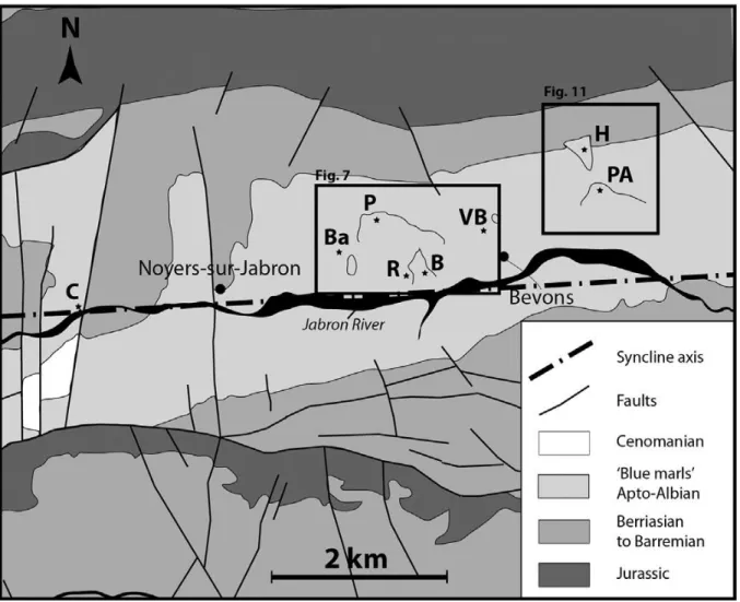
4. Stratigraphic framework of sand injectites
Because of the differential weathering and erosion of the carbonate-cemented sand injectites and the marly host formation, the sand injectites network is very well exposed in the study area (Parize, 1988). However, the mapping of the injectites and depositional sand bodies is discontinuous because of the locally dense vegetation and the presence of inaccessible escarpments. The studied outcrops are mainly located in the Bevons area (Fig. 3): Le Couvent (C), Barnèche (Ba), Le Puy (P), Les Rouines (R), La Beaume (B), Vieux-Bevons (VB), Pierree-Avon (PA) and Les Houlettes (H). One isolated site is located approximately 5 km to the west of Bevons area (Fig. 3): Le Couvent (C). They are all in the Apto-Albian succession of the northern limb of the E-W syncline. The identification of sand injectites versus depositional sand bodies is based on their geometric relationship with surrounding marls and/or presence of sedimentary structures. The key feature for identifying dykes is the intrusive nature of the sand in the shaly host rock, where sandstone bodies crosscut sedimentary layers. The sills in the study area are identified when they are concordant with the stratigraphy or slightly inclined (less than 20°). Sills are very homogenous and locally contain muddy clasts sub-parallel to the walls. In the Vocontian Basin, the depositional sand bodies contain very few sedimentary structures and are commonly very homogenous (Fries, 1987; Parize et al., 2007b). So, the identification of sills versus depositional sand layers remains difficult. Therefore, we interpreted sand bodies to be depositional if they contain at least a few sedimentary features (ripple marks, planar-convoluted laminations, bioturbational structures, stratification) (Fig. 4). In addition, sills often occur in association with dykes to form abrupt stratigraphic steps (Truswell, 1972; Hiscott, 1979; Parize et Fries, 2003).
Three types of injected sand bodies are observed in the area:
1 Dykes: they occur over the entire interval from Lower Aptian to Upper Albian, but are never found below the level of the Upper Aptian in the study area. Their thickness ranges from a few mm to over 1 m, and most are between 5 and 40 cm thick. The dykes have syn-injection current-related structures, such as flute and groove casts on their walls, and internal bands and laminae defined by glauconitic grains and clasts of the host formation, as well as faulting propagation structures, such as plumose. All of these features may be modified by post-emplacement compaction that forms “ptygmatic” folds, shears and crenulations on the dyke walls (Parize, 1988; Parize et al., 2007a,b).
2 Sills: they are concordant with the stratigraphy or slightly inclined (less than 20°). They are 1m to a few meters thick and can be followed over 1 km (Le Puy outcrop). They are well exposed in the Upper Albian marls of Le Puy Hill, La Beaume and Pierre-Avon outcrops (see
Fig. 3 for location).
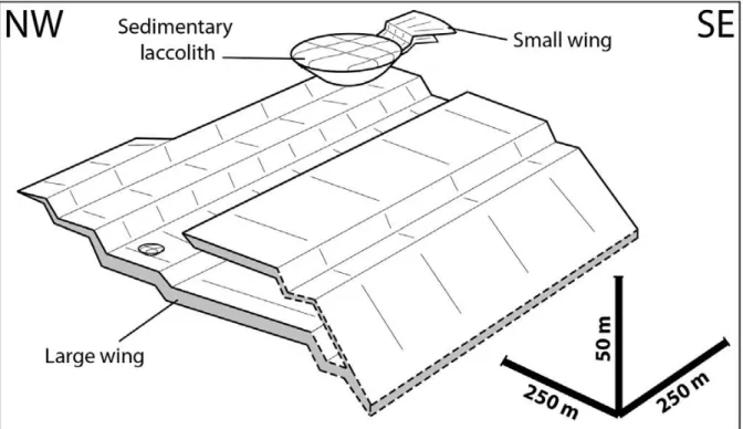
3 Sedimentary laccoliths: they have a planar base, crosscutting margins, and a convex-up top, giving a mushroom-like shape. They range from 2 m to 50 m in diameter and from 2 m to 10 m in thickness. They are massive and scattered in the Le Puy Hill, La Beaume, Vieux-Bevons and Pierre-Avon outcrops (see Fig. 3 for location).
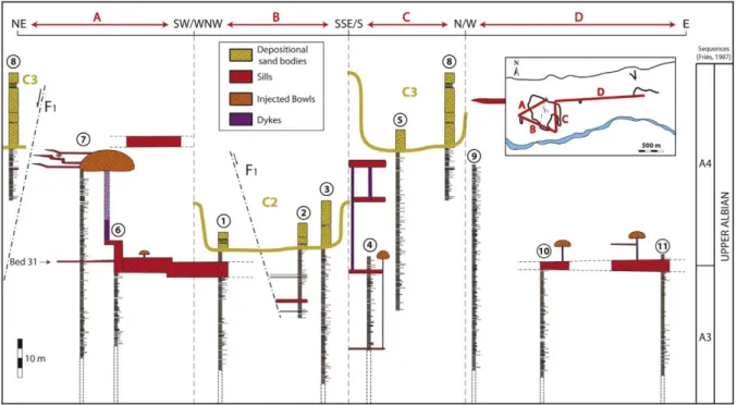
4.1. Synthesis of hosterock and turbiditic channels
The Aptian-Albian sediments correspond to pelagic deposits (Blue Marls Formation) of a deep-sea basin. The Albian marly formation is a succession of marl and limestone beds reflecting CaCO3 and total organic carbon (TOC) fluctuations (Ferry and Rubino, 1987). The limestone beds are laterally continuous and can be easily followed in the study area, providing good markers for correlation (Fig. 5). The depositional sand bodies are turbiditic channel systems approximately 100-300 m wide and 30 m thick. They are observed in Barnèche, Le Puy Hill, Les Rouines, La Beaume outcrops, and in Le Couvent outcrop (see Fig. 3 for location). They consist of well-sorted, fine-to-medium grained sand, and are essentially composed of quartz and detrital glauconitic grains, and secondary minerals (e.g. tourmaline, zircon). The depositional sand bodies seen in Barnèche, Les Rouines (logs 1, 2 and 3), La Beaume and Le Puy (logs 5 and 8) outcrops are located in the A4 unit of the Upper Albian (Fig. 5). The lower and upper channel-fill sandstone bodies are respectively named C2 and C3, and correspond to concave-up massive sandstone bodies approximately 30 m thick and hundreds of meters wide (Beaudoin et al., 1985; Fries, 1987; Parize, 1988; Parize et al., 2007b). The main direction of C2 is WNW-SSE whereas C3 is approximately oriented N-S. The paleo-currents
measured in the field tend to show that the sand source is to the west (Fries, 1987; Parize et Fries, 2003). The massive turbiditic channel system found in the Le Couvent outcrop (C1, see
Fig. 3 for location) overlies the “clansayesian bundle” (K1). The marly deposits underlying and overlying this channel contain foraminifera and nano-flora indicating that the Top is early Albian to Middle Albian age (Table 1).
We observed the thickest sills (4-12 m) in the western part of the study area. They are associated with large sedimentary laccoliths (logs 1, 6 and 7) (Fig. 5). The sills and sedimentary laccoliths of the study area are observed in a 60-80 m thick interval of host rock in the upper A3 and lower A4 units (Fig. 5). Because sills are absent in some logs (logs 3, 5 and 9), we know that some sills are not continuous all over the area. It appears however that they develop at preferential stratigraphic levels (Fig. 5).
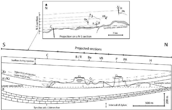
The dykes crosscut strata ranging from the Bedoulian to the Upper Albian, whereas the sills and sedimentary laccoliths are only injected in the Upper Albian between the upper A3 and lower A4 units (Fig. 5). The turbiditic channels were filled up during the Albian, more precisely the C1 channel is in the A2 unit (Lower-Middle Albian), whereas C2 and C3 channels are in the A4 unit (Upper Albian) (see Fig. 2b for the general stratigraphy). The dykes are identified in a 2km wide strip running for 5 km along the northern limb of the syncline. The sills and associated sedimentary laccoliths are identified along a 5 km long (E-W) and 1 km wide area. Injectites are also present over 500 m2 in an isolated outcrop located 5 km west of the main set (Le Couvent). The C1 and C2 channel sand bodies are aligned along the Bevons synclinal hinge zone. The C3 channel is roughly oriented N-S and is observed over 1 km from the Bevons syncline axis. The erosional base of the depositional sand bodies found in the study area is consistent with the dip direction, i.e maximum in the western and southern parts (Fig. 5). The present E-W trending syncline mainly developed during the Eocene. Prior to this structure, the area had a slight tilt of approximately 5-7° as it was located on the northern margin of the syncline during the Cretaceous sand injection (Fri_es, 1987; Parize, 1988). We inferred this tilting from the angle between the northern vertical dykes (parallel to the syncline axis) and the stratigraphy.
Finally, the projection of the channel sand bodies, the sills and dykes on a North-South cross-section shows the stratigraphical and geographical position of each sedimentary and post-sedimentary object on a vertical section at the time of sand injection (Fig. 6). The dykes are identified in Bedoulian to Upper Albian sediments but their present maximum vertical thickness is 110 m (Le Puy outcrop).
5. Architecture of sand injectites
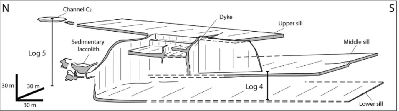
The injectite network is particularly well exposed in the Apto-Albian “Blue Marls” Formation in the La Beaume and Le Puy Area (see Fig. 3 for location). Stratigraphical correlation and precise mapping have shown that a few dykes crosscut the Apto-Albian interval over 110 m, accounting for the compaction. The sills are only observed in the upper Albian sediments. In the La Beaume outcrop (B on Fig. 7), sand injectites are observed in a 60 m thick sedimentary package in the upper Albian (see Fig. 2b for stratigraphic position). Dykes, sills and a few m thick sedimentary laccoliths, 300 m long and 100 m wide, are observed in this area (Fig. 7). Due to the crosscutting relations between the stratigraphy and the sand injectites, precise geological mapping is needed to better characterize the network in 3D. In the southern part of the La Beaume outcrop, three levels of sills are regularly spaced by about 20 m intervals (Fig. 8). The thickness decreases with depth from 5.8 m for the lower sill to 0.8 m for the upper sill (mean values). On the northern flank of the syncline, the stratigraphy is dipping 10° to the south but the sills are not exactly parallel to the stratigraphy (Fig. 8). In fact, the lower sill is horizontal, the middle sill is dipping slightly to the north and the upper sill is dipping 20° to the south. A sedimentary laccolith, approximately 10 m thick and 30 m wide, is also observed in the northern part, approximately 25 m below the base of C3 turbiditic channel system (Fig. 8). The dykes, 1-5 m wide, are the thickest observed in the area.
On the northern part of the Le Puy Hill outcrop (P on Fig. 7), a sand injectite network outcrops along a 150m high and 500m long escarpment. It is composed of centimetric to pluri-metric sills (up to about ten meters) in the Upper Albian succession which follow a horizon and jump up to a higher level to form step structures (Fig. 9) as previously shown by Waterson (1950), Beaudoin et al. (1985a) and Parize et al. (2007b). The thickness of the lower sill located on the western part decreases to the north. Two sedimentary laccoliths, 5 m thick and 10 m wide and 20 m thick and 100 m wide respectively, were identified on top of the hill (Fig. 9). The larger sedimentary laccolith shows smaller wings, 50 cm to 5 m thick and ten meters long, on its eastern flank. Additionally, on the northern outcrop, some dm-scale dykes cut the marls from bottom to top with a braided shape ending both to the top or to the bottom (anastomosing features, see Parize, 1988) (Fig. 9), and their number also increases in the vicinity of the syn-sedimentary N20 fault (F1). The vertical thickness variation along the dykes can be measured on this 100m thick outcrop. Yet, the thickness of dykes is quite constant from bottom to top (Fig. 9). At the toe of Le Puy Hill two near-parallel but differently shaped dykes were identified in the clansayesian bundle (K1) (see Fig. 2b for stratigraphic position),
where one is straight, but the other is curvilinear or winding in shape within the same stratigraphic interval (Fig. 10a,b).
Finally, these upward-climbing features are also called “wing” structures. They are commonly found in upward sand injection systems above sandy turbiditic channel-fill (Huuse et al., 2004, 2007 Jackson, 2007). A large wing propagation structure forming steps and decreasing in thickness toward the NW in the La Beaume outcrop (Fig. 11). The laccoliths are located on top of these wings.
5.2. Cm to dm dykes network: Les Houlettes-Pierre Avon and Vieux-Bevons outcrops
The Les Houlettes-Pierre Avon outcrop (H & PA on Fig. 12a) is located on the northern limb of the syncline within the middle Aptian (Gargasian) marls (see Fig. 3 for location). Only a few dykes 2-10 cm thick were identified in the area. The walls of the dykes are deformed by crenulations or micro-folds (Fig. 12b). In terms of dip, the dykes either occur as vertical structures, or are inclined at 45-60° and serve as connectors for sills creating a zigzag geometry (Fig. 12c). They can be followed laterally over tens of meters and are oriented along two main directions: N0° and N90° (Fig. 12a).
Vieux-Bevons is located on the northern limb of the syncline and east of Le Puy Hill area (see
Figs. 3 and 7 respectively for location). Only cm to dm thick dykes outcrop over a surface of approximately 2 km2 (Fig. 13). A Digital Elevation Model (DEM) was created to define the three dimensional configuration of the dyke network over the hilly and bare surface of this outcrop. The dykes crosscut Upper Aptian (“clansayesian bundle”) to Upper Albian (top A3 unit) units. They can be followed over hundreds of meters and vary in thickness from 1 cm to 40 cm without clear areal trend (Fig. 13). The dips of the dykes are bimodal like in the Les Houlettes-Pierre Avon area (see rose diagram on Fig. 13). The dykes are very sharp or winding, and crenulations deform their walls. In the Vieux-Bevons area, the sets of dykes are oriented along three major directions: N50-60° (set 1), N140-150° (set 2), and N90° (set 3) (Fig. 13). In the case of Vieux Bevons area, it is easier to represent the 3D architecture of the sand injectites network seen from the NW (Fig. 13b). The dominant set of dykes is oriented N50-60° (set 1), but it could be due to the fact that the dykes in set 1 are usually thicker than dykes in sets 2 and 3, making set 1 more visible on the field. Numerous dykes occur in the vicinity of syn-sedimentary strike-slip faults, oriented N20-30° (Fig. 13b). Whenever the angle between a dyke and a fault is larger than 45°, the dykes stop at the fault (Fig. 13a,b).
5.3. Turbiditic sand and metric dykes and sills: Le Couvent outcrop
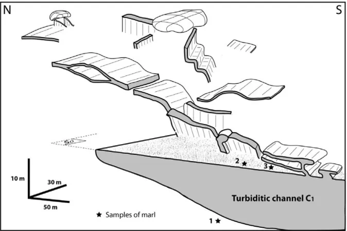
In the Le Couvent area, located about 5 km west of the Puy Hill (see Fig. 3 for location), the turbiditic channel C1 was identified at the base of the A2 unit, i.e. Top early-Middle Albian age (Table 1). This channel is about 100 m wide and it is stratigraphically located above the Clansayesian horizon (K1) (see Fig. 2b for stratigraphic position). Current ripples in the channel sands indicate a local sediment transport from W to E. Because of the dense vegetation, correlation with the Bevons area was established from biostratigraphic age dating of marls directly over and beneath the azoic sand channel. The precise geological mapping shows a network of metric sills/wings, dykes and sedimentary laccoliths directly connected to the 30 m thick sandy turbiditic channel C1 (Fig. 14). The strikes of dykes and low angle sills are between 40°N and 70°N, and sills are deformed by E-W trending folds (Fig. 14).
6. Discussion
6.1. Sand injectites vs. stress field
It is assumed that the sand injectites studied in our area are formed by hydraulic fracturing of the host rock (Beaudoin et al.,1985; Fries, 1987; Parize et al., 2007a),and consequently, intru-sion only occurs when the fluid pressure (Pf) in a sand body reaches the sum of the minimum
stress (σ3) and the tensile strength (T) of the host rock (Anderson, 1951; Hubbert and Willis,
1957;Price and Cosgrove, 1990). Because the sand injectites shouldpreserve tensile cracks parallel to the maximum compressive stress σ2, and perpendicular to the minimum
compressive stress σ3 (Anderson, 1951), we examined the composite geometry of the injectite
network in the study area to infer the principle paleo-stress directions (Delaney et al., 1986; Huang, 1988; Beacom et al.,1999; Boehm and Moore, 2002; Bureau et al., 2012),assuming σ1to be vertical for the simple tectonic case. Considering the various dyke orientations, we
chose dykes trending N50-60° (set 1) to be those that formed normal to s3 by tensile failure
because the N50e60 dykes are more abundant and usually thicker than the other sets of dykes and they are never associated with pre-existing faults. Therefore, we suggest that the N50-60° dykes (set 1) correspond to fractures perpendicular to the minimum compressive stress s3 during sand injection (Fig. 15). Consequently, the paleo-s3 direction during sand injection
would have been about N140-150° (set 2), which we infer to be related to a regional extensional direction at that time (Huang, 1988). The system of dykes studied on the
Vieux-Bevons outcrop is commonly observed in other parts of the study area (Fig. 15). It means that the minimum compressive stress (sh) was regionally oriented N140 during sand injection. The
uppermost sand injectites intruded Upper Albian sediments, indicating that injection occurred during or after this time. During sand injection, the topography of the seafloor was already folded in the study area forming a large E-W syncline structure (Fig. 7) providing a path for the turbiditic currents to the deep basin. The early Albian-late Cenomanian Durancian bulge recorded in the southern platform of the Vocontian basin (Gignoux, 1925) was also present in the study area at this time. The Durancian uplift was likely formed in response to the same NW-SE-directed extensional regime (Chorowicz and Mekarnia, 1992), which we believed controlled the overall orientation of the dykes within the injectite system where contemporaneous faults were absent (Fig. 15).
6.2. Sand injectites vs. preeexisting faults and lithology
The nucleation and propagation of sand injectites is mainly controlled by the paleostress field, the tensile strength of the rock, and the pore fluid pressure (Secor, 1965). However, the anisotropy of the host rock and/or pre-existing fractures and faults can perturb local geometry (Harms, 1965; Jolly and Sanderson, 1997). In the study area, the dykes are inferred to be mainly oriented perpendicular (set 1, N50-60°) and parallel (set 2, N140-150°) to a regional minimum compressive stress (sh) N140° during sand injection (Fig. 15). However, the
dykes can locally parallel or branch from syn-sedimentary faults (set 3, N90°) and pre-existing older and persistent faults (N20-30°). This geometry suggests that the resolved effective normal stress (sn, i.e. including fluid pressure) on these pre-existing faults was low enough to
reach their tensile strength (low resistance on pre-existing defects), and that the effective minimum principal stress (σh, also including fluid pressure) was low enough to reach the
tensile strength of the intact material and initiate optimally oriented dykes. In addition, their perpendicular orientation suggests effective stress permutation in the horizontal plane (switch between σ2 and σ3), suggesting a little initial difference between these two horizontal
components (no clear stress difference in the horizontal plane). However, the geometry at intersections, the relative abundance of set 3 and 4 dykes with respect to intersecting fault and the morphology of fault zones at intersections as opposed to away from intersections must be addressed prior to interpret whether fault planes may act as a barrier or a conduit for the fracture propagation (Fig. 15). The presence of bedding can have the same effect as
pre-existing faults on the propagation of injectites, and on that basis σh + Th > σv + Tv, where
σv is the maximum compressive stress and Tv is the vertical tensile strength, reduced by a
bedding parting in this case (Price and Cosgrove, 1990; Hillier and Cosgrove, 2002). This condition is generally satisfied when the injectites(dykes) come close to the surface, even if the depth at which a dyke turns into a sill in anisotropic sediment is a function of coupled parameters including the original sealing depth of the isolated sand body, the difference in horizontal and vertical tensile strengths, and the value of the pore fluid pressure (Vigorito and Hurst, 2010; Gressier et al., 2010). However, it is possible that very close to the sediment water interface σv is σ3. It seems quite plausible that the principle stresses “flip” positions
without changing the overall three directions of the principal stresses as the water/sediment interface is approached. The sills with the laccoliths are generally the highest structures in the network (Fig. 15), which would also be consistent with a change in the positions of the principle stresses in the paleostress geometry. In the study area, the sills are mainly observed in the Upper Albian sediments (Fig. 5), but a few of them are found close to the C1 channel in
the Lower-Middle Albian sediments (Fig. 14). Because the dips of dykes are bimodal in the study area, i.e. vertical or 45-60°, the mode of hydraulic fracturing ranges from tensile fracture (mode I) to shear dilatancy failure (mode I/II) for the same regional paleostress conditions. The dip of individual dykes does not depend on the lithology or burial of the host rock because inclined and vertical dykes are observed at the same stratigraphical level. For constant rock properties, a larger differential stress (σv-σh) favors shearing whereas a smaller
differential stress favors tensile failure (Grauls, 1999). Therefore, the mode of dyke injection depends only on the value of the horizontal compressive stress, assuming a constant vertical principle stress.
6.3. Sand injectites vs. depth and distance to the potential sand sources
Individual outcrops are approximately a few hundred meters long (La Beaume, Vieux-Bevons, Les Houlettes) and tens of meters thick (Vieux-Bevons, Le Puy). The dykes do not show any consistent thickening or thinning in a preferential direction at the scale of individual outcrops. However, some thickness variations can be established at the scale of the whole study area.
The E-W trend of the modern syncline is consistent with the inferred E-W direction of the Vocontian confined valley during the Cretaceous (Fries, 1987). Consequently, sandstone turbiditic channel infillings are mainly located in the present E-W syncline axis. Dykes and sills thin out away from the syncline axis, towards the north (Fig. 16a), meaning that they are thicker close to the sand source (i.e. the turbiditic channel C1). Using “ptygmatic” folds, shears
and crenulations on the dyke walls due to post-emplacement compaction, the stratigraphic position of the paleo-seafloor at the time of injection has been calculated between 150 and 250 m above the channel C3 (Parize, 1988; Parizeet al., 2007a,b),or between 300 and 400 m
above the newlyidentified channel C1 (Fig. 6). Sills and dykes thin up in any vertical section
for all outcrops and they start to thick again while they get closer to the surface, i.e. the paleo-seafloor. The thinning away from the feeder is compensated by the thickening towards the surface (Fig. 16b).
Stopping injectites propagation requires that the fluid pressure in the sand decreases below the sum of the minimum stress and the tensile strength of the host rock (Pf < σ3 + Т).
This decrease can result from either a pressure drop, a tensile strength increase, or a σ3
increase. The pressure drop may be due to a number of reasons including the waning fluid pressure in the sand source, the pervasive infiltration of fluid into the pore space of the host rocks (Hubbert and Willis, 1957), the frictional forces that depend on the fluid velocity and fluid viscosity, and the distance of an injectite tipeline from the sand source during propagation. The tensile strength depends on the plasticity index and the rate of loading (Kim et al., 2012). Therefore, like for the minimum compressive stress σ3, it depends on the depth,
such that the deeper the injectite body, the greater σ3 and host tensile strength.
1 Considering σ3 + T constant, the differential of pressure (ΔP = Pf - (σ3 + T)) depends on Pf: it
means that ΔPmax occurs closer to the sand source (Pfmax) (Fig. 16c).
2 Considering T and Pf constant, the differential of pressure depends on σ3: it means that
ΔPmax occurs close to the surface (σ3min) (Fig. 16c).
3 Considering Pf + σ3 constant, the differential of pressure depends on T: it means that ΔPmax
Therefore, based on the field observations, we suggest that hydrofracturing occurs until Pf < σ3 + T and that the thickness of sills and dykes increase or decrease as a function of the
differential of pressure, i.e. the greater ΔP, the thicker sand injectites (Fig. 16c).
6.4. Models of sand injection
Previous authors studying sand injectites in the Vocontian Basin have discussed the architecture of the injectite network and proposed models for downward and/or a lateral propagation of the injectites (Rutten and Schonberger, 1957; Beaudoin and Fries, 1982; Beaudoin et al., 1985a,b; Parize, 1988; Huang, 1988; Parize and Fries, 2003; Parize et al., 2007a,b). With the exception of Huang (1988),the authors favored syn-depositional injection. They suggested that during the passage of sedimentation from a high density turbidity flow in the erosive channels, the mixture of sand and seawater penetrated into pre-existing open fractures. They proposed that fractures were formed by gravity sliding perpendicular to the dip direction and parallel to the channel margins (Beaudoinand Fries, 1982; Beaudoin et al., 1985a; Fries, 1987; Parize, 1988). However, to explain the large size and complexity in the sand injectite network in the Vocontian basin, they also suggested that hydraulic fracturing was induced by centrifugal forces at outer bends of turbiditic channel systems (Beaudoin et al., 1985a; Parize et al., 2007a). The injectite network of the study area was also used to understand the early fracturing occurring in the shallow muddy sediments of deep sea marine environments (Parize et al., 2007a) or to estimate the paleostress during sand injection (Huang, 1988).
However, in most sedimentary basins, sand injectites found with sandstone turbiditic channel-fill usually propagate upward and/or laterally (e.g. Smyers and Peterson, 1971; Truswell, 1972;Hiscott, 1979; Hillier and Cosgrove, 2002; Huuse et al., 2004; Hubbard et al., 2007; Cartwright et al., 2008; Monnier et al., 2014),sometimes downward (e.g. Gottis, 1953; Parize, 1988; Huang, 1988; Scholz, 2009, 2010),and rarely in all directions(Philips and Alsop, 2000; Surlyk, 2001, 2007; Rowe et al., 2002;Ribeiro et Terrinha, 2007). Based on the precise 3D architecture ofthe sand injectite network, we propose a new model of upward and lateral sand injection in the Vocontian basin consistent with other similar studies of sand injectites (Truswell, 1972; Hiscott, 1979; Huuse et al., 2004; Levi, 2006; Hubbard et al., 2007; Jackson, 2007; Cartwright et al., 2008; Andresen et al., 2009; Vetel and Cartwright, 2009; Kane, 2010).
As shown by Fig. 5,at the time ofinjection (structure at the time of injection deduced from a low angle (<10°) between dykes and host mudstone rock) the studied dykes are restricted to a depth range between the base of the upper C3 channel and the base of the lower C1 channel.
Furthermore, the close analysis of Le Couvent outcrop shows a clear relationship between the channel C1 and upward propagated dykes. The biostratigraphical data collected in the area
shows that most dykes are originated from this initial feeder, meaning that the channel C1
was the main sand source in the area. The dykes from the channel C1 then connected to the
channels C2 and C3, and/or connected to the dykes emanating from these two upper channels,
forming a large network of injection (Fig. 15). Based on this general 3D architecture network of the sand injectite in the area, we propose 2 possible models.
6.4.1. Model 1: propagation in all directions
We demonstrated that the sand injections of the study area formed actively and that the wings propagated upward. Consequently the sand injectites cannot be interpreted as Neptunian dykes, as in a glacial environment, where sand injectites are typically injected downwards (Jolly and Lonergan, 2002) and turn parallel to the bedding with depth beneath the ice sheet (Brunn andTalbot, 1986; Boulton and Caban, 1995; Rijsdijk et al., 1999). These injectites are formed by hydraulic fracturing as a result of the loading and drag forces induced beneath an ice sheet (Boulton and Caban, 1995). Downward injections typically penetrate from a few centimeters to a few tens of meters, but the Boulton & Caban model also suggested the possibility of greater values (250e400 m) for a larger potential gradient. In the case of mass transport deposits (MTDs) composed of low porosity and permeable sediments, the same conditions are likely reached during deposition on the sea-floor. The typically mud-rich nature of these sediments can preclude fluid escape and increase the fluid pressure below by instantaneous load (Jonk, 2010). Downward sand injection has also been suggested to occur due to high sediment fallout rates within a channel system (Parize et al., 2007a). Because the dykes are partially intruded along pre-existing faults (Fig. 13), we propose a model of initial propagation of sand injectites in all directions by the process of subtrusive injection (Fig. 17b). This proposition would mean that the sand e fluid mixture of a pressurized sand body was implosively sucked downward and/or upward within re-opened high permeability faults or within vertical tensile fractures (Rowe et al., 2002; Scholz et al., 2009). Adapted to our field observations, this model implies that the subtrusive injectites are locally
downward (some dykes) and mostly upward (some dykes and all wings) (Fig. 17b). The wings developed when dykes turned parallel to the bedding because of sedimentological or mechanical heterogeneities (Parize et al., 2007a). Then, the over-pressured fluids tend to propagate upward beyond the channel margin in direction of the surface, until the overpressure drops below the fracture pressure, stopping injection (Vetel and Cartwright, 2009)(Fig. 17b). In this model, the triggering mechanism of sand injection could be related to the uplift of the Durancian during Upper Albian e Lower Cenomanian. However, this model does not account for the thickness variation of the dykes from the sand source up to the surface (Fig. 16c).
6.4.2. Model 2: lateral and upward propagation of the intrusions
Most authors who studied the Bevons outcrops suggested that sand injection occurred during, or a short time after, the deposition of Upper Albian massive sandstone turbiditic channelefill (C2 and C3) (Beaudoin et al., 1982; Fries, 1987; Parize, 1988). The interpretation
was based on the lack of any lower sand source. Our own field observations revealed that a Lower-Middle Albian sandstone turbiditic channel fill (C1) lying close to the “Clansayesian
bundle”, is also a potential sand source for sand injectites in the area. We found meter-scale dykes emanating upward from this sandstone turbiditic channel (Fig. 14). Furthermore, no evidence of dykes penetrating a lower level has been found in the area (Fig. 6). These observations mean that sand injection propagated upward and laterally from the sand source (Fig. 17c). The sand injectites of Bevons could be the result of forceful injection from an over-pressured sand body sealed by low permeability lithologies. Once the fluid overpressure exceeds the strength of the seal, hydraulic fractures can form at the top of the overpressured sand body and earthquake (Jolly and Lonergan, 2002). During the upward propagation of the fractures, the fluid pressure contained in the sand-fluid mixture can reach supralithostatic magnitudes forming sills and dykes simultaneously (Pf > σ1) (Vigorito and Hurst, 2010). The
hydraulic fracture propagates in the direction of the water pressure gradient, toward the paleo-seafloor (Fig. 17c). In this model, the sand injectites of the study area propagated from the lower-middle Albian channel (C1) toward the surface and probably penetrated into the
upper Albian channels (C2 and C3), while increasing their pore fluid pressure during continued
propagation (Fig. 17c). If the rapid influx of overpressured fluid in these channels increases their pore fluid pressure, a new set of hydraulic fractures would initiate and sand injection
would reactivate. Therefore, sand injection can be considered as the result of a chain of events leading to a connection between sand-rich sequences at different stratigraphic levels.
7. Conclusion
The Aptian-Albian formation (“Blue Marls”) of the Vocontian basin represents a field analog for the architecture of sand injectite networks commonly encountered in deep-sea environments and associated with hydrocarbon reservoirs. In the study area, the sand injectites, dykes and sills/wings, range in thickness from a few mm to several meters. They propagated through a 110 m thick interval of the host rock (compacted value) and extend laterally 1000 m away from their feeder sand body. In our study area, they are associated with large and massive, 100-200 m wide and tens of meters thick, sandstone turbiditic channel fills (C1, C2, and C3). The outcrop observations show that the morphology of the sand
injectites in the marls was governed by the local stress field, the pre-existing faults, the lithology, the compaction, and the distance to the potential sand sources:
1 3 sets of dykes are observed. The most abundant (N50-60°) represents pure hydrofracturing in a homogeneous isotropic host rock during the injection event(s). It is therefore interpreted to have been perpendicular to s3 of the formative paleostress field.
Because dykes are inferred to be indicators of the paleostress, sand injection likely happened during the Upper Albian e Lower Cenomanian, in response to the regional NW-SE extensional regime (s3) due to the Durancian uplift.
2 The other sets of dykes are oriented N140-150° (set 2) and N90° (set 3), similar to pre-existing faults. This suggests that σh + Th > σn + Tn during sand injection. At this stage, we
do not know whether the fault planes acted either as a barrier or as a conduit for hydrofracture propagation, requiring further investigations.
3 We suggest that the N50-60° dykes (set 1) correspond to fractures perpendicular to the minimum compressive stress σ3 during sand injection. Consequently, the paleo-σ3 direction
during sand injection would have been about N140-150° (set 2), which we infer to be related to a regional extensional direction at that time.
4 Field observations revealed that a Lower-Middle Albian sandstone turbiditic channel (C1)
turbiditic channels (C2 and C3) on the other hand, are potential sand sources for sand
injectites in the area. However, the turbiditic channel C1 appears to be the main sand feeder
for sand injection in the area.
5 We suggest that hydrofracturing occurs until Pf < σ3 + T and that the thickness of sills and
dykes increase or decrease as a function of the differential of pressure, i.e. the greater ΔP, the thicker sand injectites.
The injectites of the Bevons area intruded Aptian-Albian marls in an interval of depth ranging from the depth of a Middle Albian channel (C1) to the depth of Upper Albian channels
(C2 and C 3). The sand injectites originated either from C1 and/or from C2 and C3. The detailed
analysis of the 3D architecture of an outcropping network of sand injectites network in the Bevons area (SE of France) shows that the processes are most probably related to a forceful injection from an overpressured sand body sealed by low permeability lithologies.
Acknowledgment
Total is thanked for funding this project. S. Hofmann, G. Martin, J. Contet, F. Pattier, C. Fettweis, C. Lanteaume and A. Lion (fellow students) are thanked for their collaboration in the fieldwork as part of their respective degree courses. O. Parize and D. Bureau are also thanked for their useful discussions on the field. JeF. Ritz and E. Doerflinger are thanked for the loan of the differential GPS (Trimble). G. Dupont is thanked for his contribution to the biostrati-graphic analysis. We would like to thank the reviewers, Ian Kane and Ewa Stavrou (Szarawarska), and the Editor, William Dunne, for their comments and suggestions that greatly improved the manuscript.
References
Anderson, E.M., 1951. The Dynamics of Faulting and Dyke Formation with Applications to Britain. Oliver and Boyd, London, p. 206.
Andresen, K.J., Clausen, O.R., Huuse, M., 2009. A giant (3.3 x 10⁷ m3) middle Miocene (c. 15 Ma) sediment mound (M1) above the Siri Canyon, Norwegian-Danish Basin: origin and significance. Mar. Geol. 26, 1640e1655.
Baudrimont, A.F., Dubois, P., 1977. Un bassin mesogeen du domaine peri-alpin : le Sud-Est de la France. Bull. Centres Rech. Explor. Prod. Elf-Aquitaine 261-308.
Beacom, L.E., Anderson, T.B., Holdsworth, R.E., 1999. Using basement-hosted clastic dykes as syn-rifting palaeostress indicators: an example from the basal Stoer Group, northwest Scotland. Geol. Mag. 136, 301-310.
Beaudoin, B., Fries, G., 1982. Filons greseux sedimentaires per descensum, dans un systeme de fractures ouvertes. Le cas de l’Albien de Bevons (Alpes de Haute Provence). Comptes Rendus de l’Academie Des. Sci. Paris 295, 385-387.
Beaudoin, B., Fries, G., Parize, O., Pinault, M., 1985a. L’origine des injections sableuses : les sills et les dykes albiens du Ravin de la Beaume, Bevons (Alpes de Haute-Provence). Comptes Rendus de l’Academie Des. Sci. Paris, 301, 407-410.
Beaudoin, B., Fries, G., Parize, O., Pinault, M., 1985b. Sedimentary sills and dykes: characters and modes of the sand injection in fractured shaly massifs. In: 6th. Eur. Reg. Meet., Int. Assoc. Sed., Lleida. Abstract, pp. 34-37.
Beaudoin, B., Fries, G., Joseph, P., Bouchet, R., Cabrol, C., 1986. Tectonique sedimentaire cretacee de l’Ouest de la Durance (S.E. de la France). Comptes Rendus de l’Academie Des. Sci. Paris 303, 857-862.
Boehm, A., Moore, C.J., 2002. Fluidized sandstone intrusions as an indicator of Paleostress orientation, Santa Cruz, California. Geofluids 2, 147-161.
Boulton, G.S., Caban, P., 1995. Groundwater flow beneath ice sheets: Part II - its impact on glacier tectonic structures and moraine formation. Quat. Sci. Rewiews 14, 563-587.
Breheret, J.G., 1997. L’Aptien et l’Albien de la fosse vocontienne (des bordures au bassin). Evolution de la sedimentation et enseignements sur les evenements anoxiques, p. 614. These Doct. Sci. University Tours, 1995. Publ. Soc. Geol. Nord, 25.
Brunn, V.V., Talbot, C.J., 1986. Formation and deformation of subglacial intrusive clastic sheets in the Dwyka formation of northern Natal, South Africa. J. Sediment. Pet. 56, 35e44. Bureau, D., Mourgues, R., Cartwright, J., Foschi, M., Abdelmalak, M.M., 2012. Characterisation of interactions between a pre-existing polygonal fault system and sandstone intrusions and the determination of paleo-stresses in the Faroe-Shetland basin. J. Struct. Geol. 1-14. http://dx.doi.org/10.1016/j.jsg.2012.09.003.
Cartwright, J.A., James, D., Huuse, M., Vetel, W., Hurst, A., 2008. The geometry and emplacement of conical sandstone intrusions. J. Struct. Geol. 30, 854-867.
Chorowicz, J., Mekarnia, A., 1992. Mise en evidence d‘une extension albo-aptienne
orientee NW-SE en Provence (SE de la France). Comptes Rendus l‘Academie Sci. Paris 315, 861-866.
Combes, P.J., Peybernes, B., 1989. Tectonique albienne dans les gisements de bauxite
des Pyr_en_ees ari_egeoise (France) en relation avec l’evolution geodynamique de la marge passive europeenne. Comptes Rendus de l’Academie Des. Sci. Paris 308, 953-959.
Crne, A.E., Smuc, A., Skaberne, D., 2007. Jurassic neptunian dikes at Mt Mangart (Julian alps, NW Slovenia). Earth Environ. Sci. 53 (2), 249-265.
De Boer, W., Rawlinson, P.B., Hurst, A., 2007. Successful exploration of a sand injectite complex: Hamsun Prospect, Norway Block 24/9. In: Hurst, A., Cartwright, J. (Eds.), Sand Injectites: Implications for Hydrocarbon Exploration and Production, 87. AAPG Mem, pp. 65-68.
Delaney, P.T., Pollard, D.D., Ziony, J.I., McKee, E.H., 1986. Field relations between dikes and joints: emplacement processes and paleostress analysis. J. Geophys. Res. 91, 4920-4938.
Dixon, R.J., Schofield, K., Anderton, R., Reynolds, A.D., Alexander, R.W.S., Williams, M.C., Davies, K.G., 1995. Sandstone diapirism and clastic intrusion in the Tertiary Submarine fans of the Burce-Beryl Embayment, Quad 9, UKCS. In: Hartley, A.J., Prosser, D.J. (Eds.), Characterization of Deep Marine Clastic Systems, 94. Geological society Special Publication, pp. 77-94.
Ferry, S., Cotillon, P., Rubino, J.L., 1986. Comparaison des formes de l’erosion sous-marine fossiles et actuelles. Le Cretace du periclinal de Lure (chaîne subalpines française) et les flancs du canyon Shamrock (marge bretonne). Comptes Rendus de l’Academie Des. Sci. Paris 303, 935-940.
Ferry, S., Rubino, J.eL., 1987. La modulation eustatique du signal orbital dans les sediments pelagiques. CR Acad. Sci. Paris 305, 477-482.
Fries, G., 1987. Dynamique du bassin subalpin meridional de l’Aptien au Cenomanien, p. 370. These Doctorat des Sciences Universite Paris VI, 1986: Memoire des Sciences de la Terre, Ecole des Mines de Paris, 4.
Fries, G., Parize, O., 2003. Anatomy of ancient passive margin slope systems: Aptian Gravity-driven deposition on the Vocontian palaeomargin, western Alps, south-east France. Sedimentology 50, 1231-1270.
Gay, M., Moullade, M., Lorenchet de Montjamont, M., 1984. Feuille Le Buis au 1/80000, 3e ed. Carte geologique detaillee de la France de 1/80000, p. 211.
Gignoux, M., 1925. Geologie Stratigraphique. Masson et Cie, Paris.
Gottis, Ch, 1953. Les filons clastiques “intraformationnels” du “Flysch” numidien tunisien. Bull. Societe Geologique Fr. 3, 775-783. Paris, ser. 6, t.
Grauls, D., Baleix, J.M., 1994. Role of overpressures and in situ stresses in fault controlled hydrocarbon migration. Mar. Pet. Geol. 11, 734-741.
Grauls, D., 1999. Overpressures: causal mechanisms, conventional and hydromechanical approaches. Oil gas Sci. Technol. ,Rev 54 (n 6), 667-678.
Gressier, J.B., Mourgues, R., Bodet, L., Cobbold, P.R., Mathieu, J.Y., Galland, O., 2010. Control of pore fluid pressure on depth of emplacement of magmatic sills: an experimental approach. Tectonophysics 489, 1-13.
Hardenbol, J., Thierry, J., Farley, M.B., Jacquin, Th, de Graciansky, P.eC., Vail, P.R., 1998. Mesozoic and Cenozoic sequence Chronostratigraphic framework of European basins. In: De Graciansky, P.eC., Hardenbol, J., Jacquin, Th, Vail, P.R., Farley, M.B. (Eds.), Mesozoic and Cenozoic Sequence Stratigraphy of European Basins, 60. SEPM Special Publication, pp. 763-786.
Harms, J.C., 1965. Sandstone dikes in relation to Laramide faults and stress distribution in the Southern Fron Range, Colorado. Geol. Soc. Am. Bull. Boulder 76, 981-1002.
Hibsch, C., Kandel, D., Montenat, C., Ott d’Estevou, P., 1992. Evenements tectoniques cretaces dans la partie meridionale du basin subalpine (massif Ventoux-Lure et partie orientale de l’arc de Castellane, SE France). Implications geodynamiques. Bull. Soc. Geol. Fr. 163, 147-158.
Hillier, R.D., Cosgrove, J.W., 2002. Core and seismic observations of overpressure-related deformation within Eocene sediments of the Outer Moray Firth, UKCS. Pet. Geosci. 8, 141-149.
Hiscott, R.N., 1979. Clastic sills and dikes associated with deep-water sandstone, Tourelle Formation, Ordovician, Quebec. J. Sedimentol. Petroleum Tulsa 49 (n1), 1-10.
Huang, Q., 1988. Geometry and tectonic significance of Albian sedimentary dikes in the Sisteron area, SE France. J. Struct. Geol. 10, 453-462.
conglomeratic intrusions sourced from deep-water channel deposits, Cerro Toro Formation, Magallanes basin, southern Chile. In: Hurst, A., Cartwright, J. (Eds.), Sand Injectites: Implications for Hydrocarbon Exploration and Production. American Association of Petroleum Geologists Memoir, Tulsa, pp. 199-207.
Hubbert, M.K., Willis, D.G., 1957. Mechanics of hydraulic fracturing. Trans. Am. Inst. Min. Eng. 210, 153-168.
Huuse, M., Mickelson, M., 2004. Eocene sandstone intrusions in the Tampen Spur area (Norwegian North Sea Quad 34) imaged by 3D seismic data. Mar. Pet. Geol. 21, 141-155.
Huuse, M., Duranti, D., Steinsland, N., Guagena, C.G., Prat, P., Holm, K., Cartwright, J.A., Hurst, A., 2004. Seismic characteristics of large-scale sandstone intrusions in the Paleogene of the south Viking Graben, UK and Norwegian North Sea. Geol. Soc. Lond. 29, 263-278.
Huuse, M., Cartwright, J.A., Hurst, A., Steinsland, N., 2007. Seismic characterization of large-scale sandstone intrusions. AAPG 87, 21-35. Sand injectites: Implications for hydrocarbon exploration and production (eds Hurst A & Cartwright JA).
Jackson, C.A.L., 2007. The geometry, distribution, and development of clastic injections in slope systems: seismic examples from the Upper Cretaceous Kyrre Formation, Maloy Slope, Norwegian margin. AAPG 87, 37-48. Sand injectites: Implications for hydrocarbon exploration and production (eds Hurst A & Cartwright JA).
Jackson, C.A.L., Huuse, M., Barber, G.P., 2011. Geometry of winglike clastic intrusions adjacent to a deep-water channel complex: Implications for hydrocarbon exploration and production. AAPG Bull. 95 (4), 559-584.
Jenssen, A.I., Bergslien, D., Rye-Larsen, M., Lindholm, R.M., 1993. Origin of complex mound geometry of Paleocene submarine-fan sandstone reservoirs, Balder Field, Norway. In: Parker, J.R. (Ed.), Petroleum Geology of NW Europe: Proceedings of the 4th Conference, 1, pp. 135-143.
Jolly, J.H.R., Lonergan, L., 2002. Mechanisms and controls on the formation of sand intrusions. J. Geol. Soc. Lond. 159, 605-617.
Jolly, R., Sanderson, D., 1997. A Mohr circle construction for the opening of a preexisting fracture. J. Struct. Geol. 19, 887-892.
Jonk, R., 2010. Sand-rich injectites in the context of short-lived and long-lived fluid flow. Basin Res. 22, 603-621.
Joseph, Ph, Beaudoin, B., Cabrol, C., Fries, G., 1986. Tectonics or differential compaction ? the exemple of Banon fault trough (Aptian - Albin, S.E. France). In: 12th Int. Sed. Congr., Int. Assoc. Sed., Canberra. Congr. Abstr, p. 158.
Joseph, Ph, Cabrol, C., Fries, G., 1987. Blocs bascules et passes sous-marines dans le Champ de Banon (France S.E.) de l’Apto-Albien : une paleotopographie directement controlee par la tectonique synsedimentaire decrochante. C.R. Acad. Sci. 304 (n 9), 447-452. Paris, ser. 2, t.
Kandel, D., 1989. La tectonique barremo-albienne du massif Ventoux-Lure et des Baronnies occidentales (Chaînes subalpines meridionales). Mem. Geol. 38, 203.
Kane, I.A., 2010. Development and flow structures of sand injectites: the Hind Sandstone Member injectite complex, Carboniferous, UK. Mar. Pet. Geol. 27, 1200-1215.
Kim, T., Kim, T., Kang, G., Ge, L., 2012. Factors Influencing Crack-induced tensile strength of compacted Soil. J. Mater. Civ. Eng. 24 (issue 3), 315-320.
Levi, T., Weinberger, R., Aïfa, T., Eyal, Y., Marco, S., 2006. Injection mechanism of clay-rich sediments into dykes during earthquakes. Geochem. Geophys. Geosyst. 7 (2), 1e20.
Lonergan, L., Lee, N., Johnson, H.D., Cartwright, J.A., Jolly, R.J.H., 2000. Remobilization and injection in deepwater depositional systems: implications for reservoir architecture and prediction. In: GCSSEPM Foundation 20th Annual Research Conference Deep-water Reservoirs of the World, December, pp. 3-6.
Løseth, H., Wensaas, L., Arntsen, B., Hovland, M., 2003. Gas and fluid injection triggering shallow mud mobilization in the Hordaland Group, North Sea. In: Van Rensbergen, P., Hillis, R.R., Maltman, A.J., Morley, C.K. (Eds.), Subsurface Sediment Mobilization, 216. Geological Society, London, pp. 139e157. Special Publications.
MacLeod, M.K., Hanson, R.A., Bell, C.R., McHugo, S., 1999. The Alba field ocean bottom cable seismic survey: Impact on development. Lead. Edge 18, 1306-1312.
Maillart, J., Beaudoin, B., Cojan, I., Joseph, P., Pinoteau, B., 1987. Deformation synsedimentaire ou compaction differentielle: exemples dans le Sud-Est de la France. Notes Memoires Compagnie Française des Petroles 21, 249-257.
Mallarino, G., 2002. Neptunian dikes along submarine escarpments: examples from the Jurassic of Monte Kumeta, (Sicily). Boll. della Soc. Geol. Ital. 121, 377-390.
Masse, J.eP., Philip, J., 1975. Paleogeographie et tectonique du Cretace moyen en Provence : revision du concept d’isthme durancien. Rev. Geogr. Phys. Geol. Dyn. 18, 49-66.
Masse, J.-P., Philip, J., 1976. Paleogeographie et tectonique du Cretace moyen en Provence : r_evision du concept d‘Isthme Durancien. Revue de G_eogr. Physique de Geol. Dynamique 2, 49-66. XVIII, 1.
Molyneux, S., Cartwright, J.A., Lonergan, L., 2002. Conical sandstone injection structures imaged by 3D seismic in the central North Sea, UK. First break 20, 383-393.
Monnier, D., Imbert, P., Gay, A., Lopez, M., Mourgues, R., 2014. Pliocene sand injectites from a submarine lobe fringe during hydrocarbon migration and salt diapirism: a seismic example from the Lower Congo Basin. Geofluids 14 (issue 1), 1-19.
Montenat, C., Janin, M.eC., Barrier, P., 2004. L’accident du Toulourenc : une limite teconique entre la plateforme provençale et le Bassin vocontien de l’Aptien-Albien (SE France). C. R. Geosci. 336, 1301-1310.
Obermeier, S.F., 1989. The New Madrid Earthquakes; an Engineering Geologic Interpretation of Relict Liquefaction Features, p. 114. US Geological Survey Professional Paper 1336-B.
Obermeier, S.F., 1996. Use of liquefaction-induced features for paleoseismic analysis - an overview of how seismic liquefaction features can be distinguished from other features and how their regional distribution and properties of source sediment can be used to infer the location and strength of Holocene paleo-earthquakes. Eng. Geol. 44, 1-76.
Parize, O., 1988. Sills et dykes greseux sedimentaires: paleomorphologie, fracturation precoce, injection et compaction: These Doctorat Geologie, Ecole Nationale Superieure des Mines de Paris-Universite Lille I. Memoire Sci. la Terre, Ecole Mines Paris (no. 7), 333.
Parize, O., Fries, G., 2003. The Vocontian clastic dykes and sills: a geometric model. In: Van Rensbergen, P., Hillis, R.R., Maltman, A.J., Morley, C.K. (Eds.), Subsurface Sediment Mobilization: Geological Society (London) Special Publication, 216, pp. 51-72.
Parize, O., Beaudoin, B., Eckert, S., Fries, G., Hadj-Hassen, F., Schneider, F., Su, K., Tijani, M., Trouiller, A., de Fouquet, C., Vandromme, R., 2007a. The Vocontian Aptian and Albian syndepositional clastic sills and dikes: a field-based mechanical approach to predict and model the early fracturing of marly-limy sediments. In: Hurst, A., Cartwright, J. (Eds.), Sand Injectites: Implications for Hydrocarbon Exploration and Production, 87. AAPG Memoir, pp. 163-172.
Parize, O., Beaudoin, B., Champanhet, J.-M., Fries, G., Imbert, P., Labourdette, R., Paternoster, B., Rubino, J.eL., Schneider, F., 2007b. A methodological approach to clastic injectites: from field analysis to seismic modeling Examples of the Vocontian Aptian and Albian injectites
(southeast France). In: Hurst, A., Cartwright, J. (Eds.), Sand Injectites: Implications for Hydrocarbon Exploration and Production, 87. AAPG Memoir, pp. 173-183.
Philips, C.A., Alsop, G.I., 2000. Post-tectonic clastic dykes in the Dalradian of Scotland and Ireland: implications for delayed lithification and deformation of sediments. Geol. J. 35, 99-110.
Price, N.J., Cosgrove, J.W., 1990. Analysis of Geological Structures. Cambridge University Press, Cambridge, p. 502.
Ribeiro, C., Terrinha, P., 2007. Formation, deformation and certification of systematic clastic dykes in a differentially lithified carbonate multilayer. SW Iberia, Algarve Basin, Lower Jurassic. Sediment. Geol. 196, 201-215.
Richter, D., 1966. On the new red Sandstone neptunian dykes of the Tor Bay area (Devonshire). Proc. Geol. Assoc. 77 (2), 172-186.
Ricou, L.E., Lamotte, Frizon de, 1986. Decrochement senestre medio-cretace entre
Provence et Alpes-Maritimes (Alpes occidentales, France). Rev. Geol. Dyn. Geog. Phys. Paris 27, 3-4, 237-245.
Rijsdijk, K.F., Owen, G., Warren, W.P., McCaroll, D., van der Meer, J.J.M., 1999. Clastic dykes in over-consolidated tills: evidence for subglacial hydrofracturing at Killiney Bay, eastern Ireland. Sediment. Geol. 129, 111-126.
Roure, F., Brun, J.P., Colletta, B., Vially, R., 1994. Multiphase extensional structures fault reactivation, and petroleum plays in the Alpine Foreland Basin of Southeastern France. In: Mascle, A. (Ed.), Hydrocarbon and Petroleum Geology of France. European Association of Petroleum Geoscientists Special Publication, 4. SpringereVerlag, Paris, pp. 245-268.
Rowe, C.A., Mustard, P.S., Mahoney, J.B., Katnick, D.C., 2002. Oriented clastic dike swarms as indicators of paleoslope? an example from the Upper Cretaceous Nanaimo group, Canada. J. Sediment. Res. 72 (n 1), 192-200.
Rubino, J.eL., 1982. Les gres apto-albiens du bassin Vocontien et de sa bordure occidentale. In: 9eme Reun. Sci. Terre, Paris. Societe Geologique de France ed.,
Programme-Resumes, p. 560.
Rubino, J.eL., 1984. Sedimentology of Upper Aptian-Albian turbidites and shelf sandstones in Vocontian basin (SE France). In: 5th. Eur. Reg. Meet., Int. Assoc. Sed., Marseille. Abstr, pp. 388-389.
Rubino, J.eL., Delamette, M., 1985. The Albian shelf of South East France: an example of clastic distribution dominated by oceanic currents. In: 6th European Regional Meeting of Sedimentology, Lleida, Book of Abstracts, pp. 399-402.
Rubino, J.eL., 1989. Introductory remarks on Upper Aptian to Albian siliciclastic/carbonate depositional sequences. In: Ferry, S., Rubino, J.eL. (Eds.), Mesozoic Eustacy on Western Tethyan Margins; Post-Meeting Field Trip in the ‘‘Vocontian Trough’’, 12. Publication de l’Association des Sedimentologistes Français, pp. 28-45.
Rubino, J.eL., Parize, O., 1989. Caracteristiques des systemes turbiditiques silicoclastiques Apto-albiens du bassin vocontien (SE de la France): position sequentielle - comparaison avec l’actuel. Memoire de l’Association Sedimentologues français 10, 253-254.
Rutten, M.G., Schonberger, H.J.M., 1957. Syn-sedimentary sandstone-dykes in the Aptian of the Serre-Chaitieu, Southern France. Geol. Minjbouw, La Haye, N. Ser. 19 (n 1), 214-220.
Scholz, H., Frieling, D., Obst, K., 2009. Funnel structures and clastic dykes in Cambrian sandstones of southern Sweden - indications for tensional tectonics and seismic events in a shallow marine environment. N. Jb. Geol. Paleaont. Abh. 251, 355-380.
Scholz, H., Frieling, D., Aehnelt, M., 2010. Synsedimentary Deformational Structures Caused by Tectonics and Seismic Events - Example from the Cambrian of Sweden, Permian and Cenozoic of Germany, ISBN 978-953-307-595-2. New Frontiers in Tectonic Research - General Problems, Sedimentary Basins and Island Arcs, Evgenii V. Sharkov.
Secor, D.T., 1965. Role of fluid pressure in jointing. Am. J. Sci. 263, 633-646.
Shoulders, S., Cartwright, J.A., 2004. A new approach to constraining the depth and timing of large-scale sandstone intrusions. Geology 32 (no.8), 661-664.
Shoulders, S.J., Cartwright, J., Huuse, M., 2007. Large-scale conical sandstone intrusions and polygonal faults systems in Tranche 6, Faroe-Shetland Basin. Mar. Pet. Geol. 24, 173-188.
Sibson, R.H., 1995. Selective fault reactivation during basin inversion: potential for fluid redistribution through fault-valve action. In: Buchanan, J.G., Buchanan, P.G. (Eds.), Basin Inversion, 88. Geol. Soc. Lond. Spec. Publ., pp. 3-19
Smyers, N.B., Peterson, G.L., 1971. Sandstone dikes and sills in the Moreno Shale, Panoche Hills, California. GSA Bull. 82, 3201-3208.
Souquet, P., 1978. Presentation d’une nouvelle esquisse structurale de la chaîne alpine des Pyrenees. Bull. Soc. Geol. Fr. 5, 711-712. XX.