Publisher’s version / Version de l'éditeur:
Questions? Contact the NRC Publications Archive team at
PublicationsArchive-ArchivesPublications@nrc-cnrc.gc.ca. If you wish to email the authors directly, please see the first page of the publication for their contact information.
https://publications-cnrc.canada.ca/fra/droits
L’accès à ce site Web et l’utilisation de son contenu sont assujettis aux conditions présentées dans le site LISEZ CES CONDITIONS ATTENTIVEMENT AVANT D’UTILISER CE SITE WEB.
Client Report (National Research Council of Canada. Construction), 2016-03-31
READ THESE TERMS AND CONDITIONS CAREFULLY BEFORE USING THIS WEBSITE. https://nrc-publications.canada.ca/eng/copyright
NRC Publications Archive Record / Notice des Archives des publications du CNRC :
https://nrc-publications.canada.ca/eng/view/object/?id=b87ba16f-3d71-4a45-888c-04bf357e6ca2 https://publications-cnrc.canada.ca/fra/voir/objet/?id=b87ba16f-3d71-4a45-888c-04bf357e6ca2
NRC Publications Archive
Archives des publications du CNRC
For the publisher’s version, please access the DOI link below./ Pour consulter la version de l’éditeur, utilisez le lien DOI ci-dessous.
https://doi.org/10.4224/23004643
Access and use of this website and the material on it are subject to the Terms and Conditions set forth at
Fire endurance of exposed cross-laminated timber floor for tall
buildings
Fire Endurance of Exposed
Cross-Laminated Timber Floor for Tall
Buildings
Author Joseph Z. Su, Ph.D. Approved Cameron McCartney Program LeaderMid-rise Wood Buildings, NRC Construction
Report No: A1-008570.1 Report Date: 31 March 2016 Contract No: A1-008570 Agreement date: 16 February 2016 Program: Mid-rise Wood Buildings
15 pages
Copy no. 1 of 5 copies This report may not be reproduced in whole or in part without the written consent of the National Research Council Canada and the Client.
Table of Contents
List of Figures ... ii
1 Introduction ... 1
2 Test Specimen ... 1
2.1 Full-scale floor assembly ... 1
2.2 Mode of restraint ... 6 3 Test Procedure ... 6 3.1 Instrumentation ... 6 3.2 Loading ... 8 4 Test Results ... 9 4.1 Observations ... 9 4.2 Temperatures ...10 4.3 Deflection ...11 4.4 Failure ...12 4.5 Differential pressure ...12
5 Fire Endurance Period ...13
Acknowledgement ...13
List of Figures
Figure 1. Full-scale floor assembly drawing. ... 2
Figure 2. Spline joint and nailing for the floor assembly. ... 3
Figure 3. Exposed side of the floor assembly placed onto the standard testing furnace. ... 3
Figure 4. Base layer of cement boards on unexposed side. ... 4
Figure 5. Face layer of cement boards on unexposed side. ... 5
Figure 6. View of the floor assembly support from the exposed side (underside). ... 6
Figure 7. Location of thermocouples on the unexposed side of the floor assembly (topside). ... 7
Figure 8. Location of displacement gauges on the unexposed side of the floor assembly. ... 7
Figure 9. Floor hydraulic loading system. ... 8
Figure 10. Load and deflection readings during floor assembly preloading period. ... 9
Figure 11. Temperature, load and deflection measurements during the floor test. ...10
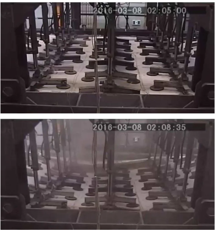
Figure 12. Deflection of the floor assembly at 125 min and 128.5 min viewed from the unexposed side. ...11
Figure 13. Exposed side of the floor assembly after testing showing the extent of charring and deflection. ...12
Fire Endurance of Exposed Cross-Laminated Timber
Floor for Tall Buildings
1 Introduction
Cross-laminated timber (CLT) can be used as a structural material in tall buildings. To support the use of CLT in tall wood buildings, fire endurance data is required for its structural
assemblies. This report presents the results of a standard fire endurance test performed on a full-scale floor assembly in accordance with ASTM E119-15 and CAN/ULC-S101-14. The floor assembly was constructed at NRC and subjected to a standard fire endurance test inside NRC’s full-scale floor furnaces (no hose stream test was performed).
2 Test Specimen
2.1 Full-scale floor assembly
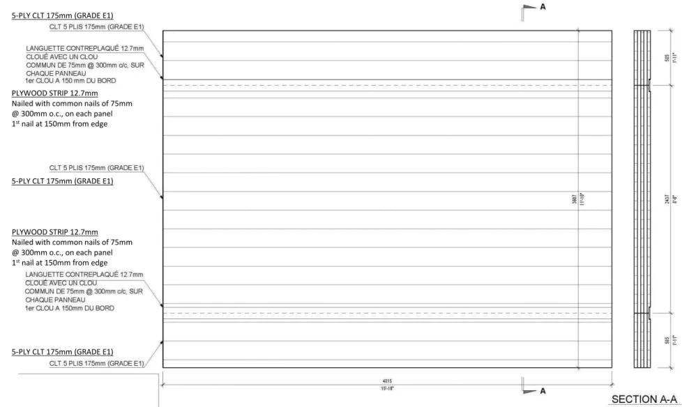
The floor assembly, which measured 4815 mm (15'-10") in length by 3607 mm (11'-10") in width, was constructed from three panels of 175 mm thick 5-ply CLT of grade E1 manufactured by Nordic. The panels were aligned such that the grain of the outer layers of timber (on both the exposed and unexposed sides) ran along the length of the floor assembly. The CLT panels were joined on the unexposed side with strips of 12.7 mm thick plywood nailed on each panel every 300 mm (starting at 150 mm from the edge of the assembly) with common 75 mm metal nails. Figure 1 and Figure 2 show drawings of the full-scale floor assembly and details of its spline joints and nailing schedule.
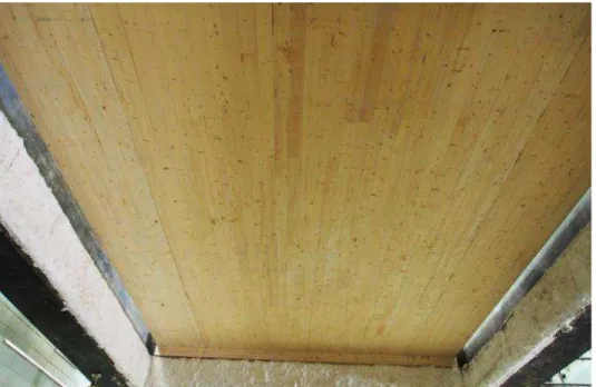
The exposed side of the assembly was a bare CLT surface. Figure 3 shows the exposed side of the assembly installed inside the standard floor furnace.
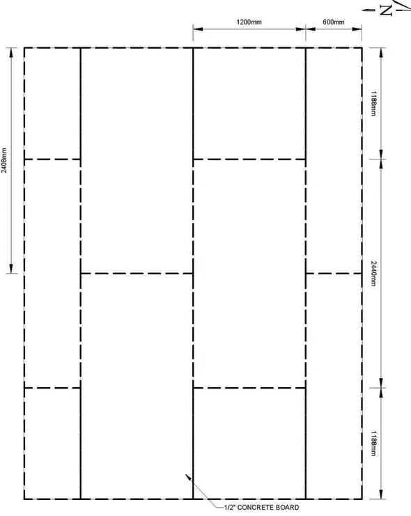
On the unexposed side, the CLT panels were covered with two staggered layers of 12.7 mm thick cement boards. The cement boards were manufactured from Portland cement, fly ash, expanded clay aggregate or expanded shale and a blend of proprietary mineral-based ingredients and fiber glass scrim. Expansion joints of a minimum of 3 mm (⅛") were created between the board sections. The cement boards were fastened to the CLT panels with 51 mm (2") long flat head zinc steel countersunk size 8 wood screws. Screws were spaced 610 mm apart starting 19 mm (¾") from the edge of the cement boards. Figure 4 and Figure 5 show the installation of the base layer and face layer of cement boards in a staggered pattern.
Figure 1. Full-scale floor assembly drawing. PLYWOOD STRIP 12.7mm
Nailed with common nails of 75mm @ 300mm o.c., on each panel 1st nail at 150mm from edge 5-PLY CLT 175mm (GRADE E1)
5-PLY CLT 175mm (GRADE E1)
5-PLY CLT 175mm (GRADE E1) PLYWOOD STRIP 12.7mm Nailed with common nails of 75mm @ 300mm o.c., on each panel 1st nail at 150mm from edge
Figure 2. Spline joint and nailing for the floor assembly.
Figure 3. Exposed side of the floor assembly placed onto the standard testing furnace.
2.2 Mode of restraint
The floor assembly was unrestrained. The assembly was only supported lengthwise on the furnace frame at both extremities. Three planks of 38 mm x 89 mm (2"x4") dimensional lumber were used on each end of the assembly to act as supports and lift the structural CLT panels so that the widthwise edges of the floor assembly remained unsupported. Figure 6 shows the assembly support from the exposed side.
Figure 6. View of the floor assembly support from the exposed side (underside). 3 Test Procedure
The test assembly was subjected to a fire endurance test following the requirements of
ASTM E119-15 and CAN/ULC-S101-14. This section describes the instrumentation as well as the loading applied to the assembly.
3.1 Instrumentation
A total of nine type K thermocouples were installed on the unexposed face of the floor assembly to monitor temperature rise throughout the test. The unexposed side thermocouples were held against the unexposed face of the assembly with felted refractory pads. Small weights were used to maintain contact between the thermocouples and the unexposed surface of the assembly. Figure 7 shows the location of the thermocouples on the unexposed side of the assembly.
Figure 7. Location of thermocouples on the unexposed side of the floor assembly (topside).
The deflection of the floor assembly was measured throughout the test duration. A total of nine linear position transducers were installed on the unexposed side of the floor assembly to monitor displacement. The displacement gauges used in the test have a precision of 0.1 mm within an accuracy of 0.4 mm. Figure 8 shows the location of the displacement gauges on the unexposed side of the assembly.
Two differential pressure sensors were installed at the centre of the full-scale floor furnace to monitor the differential gas pressure throughout the test. The differential pressure sensor utilizes a variable capacitance pressure transducer combined with a glass-clad silicon chip, having an accuracy of 0.25% and a thermal coefficient of ±0.01%/°F. One pressure sensor was located at 0.75 m and the other was located at 2.55 m below the exposed specimen surface.
3.2 Loading
A superimposed load of 4.40 kN/m² (91.8 psf) was specified by the client for this test. Loading was applied to the floor assembly through a system of 30 hydraulic cylinders each distributing its load over a set of three loading pads. Figure 9 shows the system of hydraulic cylinders used to apply the superimposed floor load.
Figure 9. Floor hydraulic loading system.
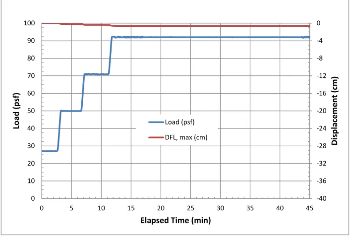
In accordance with ASTM E119-15 and CAN/ULC-S101-14, preloading was applied in four increments of 25% of the total load, and deflections were allowed to stabilise between each preload increment. Figure 10 shows the load applied to the floor assembly and the deflections measured throughout the floor over the preload period. The maximum deflection under the full load was 0.7 cm at the centre of the floor assembly during preloading.
Figure 10. Load and deflection readings during floor assembly preloading period. 4 Test Results
A full-scale standard fire endurance test was performed on the floor assembly on 8 March 2016. The test was terminated after 128.5 min of elapsed test time.
4.1 Observations
Video cameras were used to record the behaviour of the exposed side and unexposed side of the floor assembly. Figure 11 shows the results of the test.
The entire exposed CLT face was engulfed in flames within 32 seconds after the start of the test. During the first 18 min, the furnace temperature oscillated near the standard temperature curve as shown in Figure 11. When the furnace temperature went beyond the standard curve due to the CLT burning, the furnace shut down to compensate and the CLT then ceased flaming during this period. When the furnace temperature returned to the standard curve, the furnace restarted and the CLT surface engulfed in flames again. This furnace on-and-off cycle continued for the first 18 minutes. Afterwards, the exposed CLT surface was fully involved in the fire till the end of the test.
Fall-off of large pieces of wood char from the exposed side was visible after 60 min and after
-40 -36 -32 -28 -24 -20 -16 -12 -8 -4 0 0 10 20 30 40 50 60 70 80 90 100 0 5 10 15 20 25 30 35 40 45
Di
sp
la
cem
e
n
t
(cm
)
Load
(ps
f)
Elapsed Time (min)
Load (psf) DFL, max (cm)
around the perimeter of the floor assembly. The structural failure of the floor assembly occurred at 128.5 min.
Figure 11. Temperature, load and deflection measurements during the floor test. 4.2 Temperatures
Over the duration of the test, the temperature of the furnace was measured using nine thermocouples evenly distributed inside the furnace, as required by ASTM E119-15 and
CAN/ULC-S101-14. Figure 11 compares the average furnace temperature as a function of time to the standard time-temperature curve for control of fire tests defined by ASTM E119-15 and CAN/ULC-S101-14. Accurate furnace control was achieved over the entire duration of the test. The area under the average furnace temperature curve falls within 0.4% of the area of the standard time-temperature curve, meeting the 5% requirement established by the standard. Figure 11 also shows the maximum temperature measured on the unexposed side of the floor assembly. The temperature of the unexposed side of the floor assembly remained below 23°C throughout the test duration with no temperature rise.
-55 -50 -45 -40 -35 -30 -25 -20 -15 -10 -5 0 0 100 200 300 400 500 600 700 800 900 1000 1100 0 15 30 45 60 75 90 105 120 135
Di
sp
la
cem
e
n
t
(cm
)
Te
m
p
e
ra
tu
re
(°
C)
or
L
oad
(ps
f)
Elapsed Time (min)
E119 standard temperature curve (°C) Average furnace temperature (°C)
maximum temperature on unexposed side (°C) Load (psf)
4.3 Deflection
Figure 11 shows the load applied to the floor assembly and the maximum deflection of the floor over the duration of the experiment. The deflection measurements have a precision accuracy of better than 1 mm. The floor began deflecting rapidly after 125 min. The floor assembly
sustained the applied load of 4.40 kN/m-2 (91.8 psf) until 128.5 min of testing had elapsed.
4.4 Failure
According to ASTM E119-15 and CAN/ULC-S101-14, the fire endurance period of an
unrestrained floor assembly is defined by the period over which: the floor sustained the applied load without passage of flames or gases hot enough to ignite cotton pads; the average
temperature measured on the unexposed side of the floor assembly did not exceed 140°C above the initial average temperature of the unexposed side; and no individual temperature measured on the unexposed side of the floor assembly exceeded 180°C above the initial temperature.
The floor assembly failed structurally as a result of excessive deflection and inability to carry the superimposed load after 128.5 min. At this time, the temperatures on the unexposed side of the floor assembly remained well below the failure criteria defined in ASTM E119-15 and CAN/ULC-S101-14. Figure 13 shows the condition of the floor assembly after testing. The deflection of the floor is evident in Figure 12 and Figure 13. The average depth of charring is 2.5 plies and the maximum depth is 3 plies out of the 5-ply CLT panels.
Figure 13. Exposed side of the floor assembly after testing showing the extent of charring and deflection.
4.5 Differential pressure
Figure 14 shows the differential pressure inside the standard fire test furnace as a function of elapsed test time. The measurements have a precision accuracy of better than 0.1 Pa.
Figure 14. Average differential pressure inside the furnace as a function of time.
5 Fire Endurance Period
The fire endurance period of the exposed 175-mm thick 5-ply CLT floor assembly, tested under the superimposed load of 4.40 kN/m² (91.8 psf), was 128.5 minutes. The structural failure of the full-scale test assembly occurred as a result of a loss of load-carrying capacity. A hose stream test was not performed on the full-scale floor assembly.
Acknowledgement
The author would like to acknowledge Patrice Leroux, Pier-Simon Lafrance, Karl Gratton, Eric Gibbs and Robert Berzins for constructing the test assembly and conducting the fire test. References
ASTM E119-15, Standard Test Methods for Fire Tests of Building Construction and Materials, ASTM International, West Conshohocken, PA, 2015, www.astm.org.
CAN/ULC-S101-14, Standard Methods of Fire Endurance Tests of Building Construction and Materials, ULC Standards, National Standard of Canada, ULC Standards, Ottawa, ON, 2014,
www.ulc.ca. -60 -40 -20 0 20 40 60 0 15 30 45 60 75 90 105 120 135 D iff e re n tial Pr e ssur e