Publisher’s version / Version de l'éditeur:
Fire Safety Journal, 42, January, pp. 25-42, 2007-01-01
READ THESE TERMS AND CONDITIONS CAREFULLY BEFORE USING THIS WEBSITE. https://nrc-publications.canada.ca/eng/copyright
Vous avez des questions? Nous pouvons vous aider. Pour communiquer directement avec un auteur, consultez la première page de la revue dans laquelle son article a été publié afin de trouver ses coordonnées. Si vous n’arrivez pas à les repérer, communiquez avec nous à PublicationsArchive-ArchivesPublications@nrc-cnrc.gc.ca.
Questions? Contact the NRC Publications Archive team at
PublicationsArchive-ArchivesPublications@nrc-cnrc.gc.ca. If you wish to email the authors directly, please see the first page of the publication for their contact information.
NRC Publications Archive
Archives des publications du CNRC
This publication could be one of several versions: author’s original, accepted manuscript or the publisher’s version. / La version de cette publication peut être l’une des suivantes : la version prépublication de l’auteur, la version acceptée du manuscrit ou la version de l’éditeur.
For the publisher’s version, please access the DOI link below./ Pour consulter la version de l’éditeur, utilisez le lien DOI ci-dessous.
https://doi.org/10.1016/j.firesaf.2006.06.008
Access and use of this website and the material on it are subject to the Terms and Conditions set forth at
A Study of portable water mist fire extinguishers used for extinguishment of multiple fire types
Liu, Z. G.; Kim, A. K.; Carpenter, D. W.
https://publications-cnrc.canada.ca/fra/droits
L’accès à ce site Web et l’utilisation de son contenu sont assujettis aux conditions présentées dans le site LISEZ CES CONDITIONS ATTENTIVEMENT AVANT D’UTILISER CE SITE WEB.
NRC Publications Record / Notice d'Archives des publications de CNRC: https://nrc-publications.canada.ca/eng/view/object/?id=ca857a5f-9e82-44a9-bb60-79e4c2695455 https://publications-cnrc.canada.ca/fra/voir/objet/?id=ca857a5f-9e82-44a9-bb60-79e4c2695455
http://irc.nrc-cnrc.gc.ca
A S t u d y o f p o r t a b l e w a t e r m i s t f i r e
e x t i n g u i s h e r s u s e d f o r e x t i n g u i s h m e n t o f
m u l t i p l e f i r e t y p e s
L i u , Z . ; K i m , A . K . ; C a r p e n t e r , D .
N R C C - 4 9 2 5 9
A v e r s i o n o f t h i s d o c u m e n t i s p u b l i s h e d i n
/ U n e v e r s i o n d e c e d o c u m e n t s e t r o u v e
d a n s : F i r e S a f e t y J o u r n a l , v . 4 2 , J a n .
2 0 0 7 , p p . 2 5 - 4 2 d o i :
1 0 . 1 0 1 6 / j . f i r e s a f . 2 0 0 6 . 0 6 . 0 0 8
A STUDY OF PORTABLE WATER MIST FIRE EXTINGUISHERS USED FOR EXTINGUISHMENT OF MULTIPLE FIRE TYPES
Zhigang Liu*, Andrew K. Kim and Don Carpenter Fire Research Program, Institute for Research in Construction, National Research Council of Canada, Ottawa, Ontario, Canada, K1A 0R6,
A BSTRA CT
This paper describes both theoretical and experimental studies on the application of a portable water mist extinguisher in suppressing multiple fire types. Two prototype portable water mist fire extinguishers were developed and their feasibility in extinguishing flammable liquid, cooking oil and wood crib fires, and for use in fires associated with an energized target was investigated. The interaction between water mist and the fire plume was studied by analyzing the instantaneous process of fire extinction, and fire and fuel temperature profiles. Both theoretical analysis and experimental results showed that the extinguishing mechanisms and process as well as water mist characteristics required (such as water flux density, droplet size and spray coverage) change with the types of fires encountered. The portable water mist extinguisher with appropriate mist characteristics was able to extinguish multiple fire types.
Key Words:water mist, portable extinguisher, multiple fire types and fire suppression.
NOMENCLATURE
Aw- Water mist coverage area (m
2
),
c
a - Coefficient for the effective spray coverage,
p
C - Thermal capacity (J/mol.K), pwv
C - Thermal capacity of the water vapour (J/mol.K), D - Dimension of the fuel container (m),
d - Diameter of water drop (m),
Dv0.9 - Drop diameter such that 90% of the total liquid volume is in drops of smaller
diameter (µm),
c H
∆ - Heat of combustion of the fuel (kJ/mol),
c
f - Fraction of heat of combustion of the fuel (∆Hc) that is transferred to the fuel from the flame,
k – heat transfer coefficient (W/m.K) (Eq. 10-12),
L - Discharge distance from the nozzle tip to the fuel surface (m), vf
L - Latent heat of evaporation of the fuel (kJ/mol),
vw
L - Latent heat of evaporation of water (kJ/mol), f
m& - Fuel burning rate,
*
w
m& - Water mist discharge rate (kg/s),
P - Discharge pressure (kPa), f
Q& - Rate of heat that is transferred to the fuel surface from the flame (kW),
E
Q& - Rate of external heat transferred to the fuel (kW), L
Q& - Rate of heat loss from the fuel (kW),
q& - Rate of heat (kW)
S - Rate of transfer of ‘sensible heat’ at the surface area of the fuel,
T - Temperature (K),
wp
T - Water boiling temperature (K), max
f
u - Maximum upward velocity in a fire plume (m/s),
w
u - Water droplet velocity (m/s), wo
u - Initial water droplet velocity (m/s),
x - Fraction of water mist that is involved in flame cooling,
Greek symbols
α - Spray angle,
w
ρ - Water density (kg/m3)
φ - Mass air to fuel ratio
δ - Thickness of heating layer below the fuel surface (m),
ε - Emissivity, σ - Stefan-Boltzmann constant (5.67 X 10⁻⁸ W/m2.K4) Subscripts a – air, cond – conductive conv – convective, f – fuel,
fl – heat loss from fuel surface fs – fuel surface
fo – inside the fuel, rad - radiation w – water,
1. INTRODUCTION
Fire extinguishers are important items of safety equipment used to prevent life and property losses caused by fires. Two recent surveys carried out in the UK and in Europe showed that in almost 80% of fires, fire extinguishers were used to put out the fires in their incipient stages [1, 2]. A fire service was not called or involved in the vast majority of cases. The fires were effectively dealt with by the use of fire extinguishers and small fires were prevented from becoming large ones.
The most common fire extinguishers currently used are water, powder, foam and carbon dioxide. They are capable of extinguishing one or two types of fire but the goal of finding one extinguisher that will deal effectively with any type or class of fire has not been achieved [3]. For example, water extinguishers are mainly used to extinguish a fire associated with wood, textiles and paper (Class A). Foam extinguishers, with a solution of aqueous film-forming foam (AFFF), are effective on Class A and Class B fires. However, AFFF is being phased out due to both environmental and toxicological concerns and efforts are being made to seek more environmentally-friendly products [4]. A dry powder extinguisher is mainly used against Class B and C fires, and its performance in tackling a cooking oil fire is not efficient because of its poor cooling ability. It causes obscuration when used in confined places and the residual mess creates a clean-up problem. Carbon dioxide is a preferred suppressant for fires that involve a live electrical risk but it is not used to extinguish Class A and cooking oil fires (Class K). Recent research also showed that acid gas by-products are generated in fire suppression when halocarbon streaming agents, such as FM-200 and FE-36, are used to extinguish a fire [5]. Potential exposure to the acid by-products is tolerable in an open space but its concentration in small enclosures is at dangerous levels.
Water mist that consists of small water droplets (Dv99 < 1000µm) is non-toxic and
environmentally friendly, and is relatively easy to clean up after fire suppression is completed. The study and description of the fundamental principles of extinguishment of liquid and solid fuel fires with water mist can be traced back to the mid-1950s [6-8]. Over the last two decades, water mist has demonstrated its capabilities in extinguishment of multiple fire types from Class A fires in shipboard accommodation spaces, office and residential buildings, and heritage property (wood stave churches, libraries) and Class B spray and pool fires in machinery spaces, gas turbine enclosures, bulk conveyors to Class C fires in computer and electronics equipment and Class K fires in commercial cooking areas [9 –15].
Water mist systems, according to their applications, can be distinguished into three types: total compartment application (TCA), local application (LA) and zoned application (ZA) systems [10]. For a TCA system, water is discharged from all nozzles distributed throughout the compartment. A large enclosed fire can be extinguished by a TCA system as the oxygen concentration in the compartment is quickly reduced due to the consumption by the fire and the displacement by water vapour. An LA water mist system, is arranged to discharge directly to an object or hazard in an enclosed, partially enclosed, or open outdoor area. It extinguishes a fire mainly by cooling flames and/or by cooling the fuel surface.
A portable water mist extinguisher is a typical local water mist application. However, unlike a fixed LA system, it has a limited water supply and small spray coverage. Its discharge pressure declines quickly during discharge. The extinguishing mechanisms and water mist characteristics required, such as droplet size, water flux density, and spray coverage, change with the types of fires encountered. As indicated by Rasbash in his early water mist research [16], the liquid fires can be extinguished with
water mist by either cooling the fuel or/and cooling the flame, depending on fuel property, while the solid fires are extinguished mainly by cooling the fuel. He and other researchers [16-18] also tried to quantify water mist characteristics required for fire extinguishment through both theoretical and experimental studies. Although general principles have been understood, information on water mist characteristics required for extinguishing various types of fires is still limited. This has restricted the development of water mist fire suppression technologies. Currently, only one commercially-available water mist fire extinguisher has been developed for use in extinguishing Class A and Class C fires [19] that are both solid fires. No portable water mist extinguisher has been studied and developed in extinguishing liquid fires or both solid and liquid fires.
The objective of the present work is to study water mist characteristics required for various types of fires both theoretically and experimentally. Two prototype water mist extinguishers were developed and their capability and limitation in suppressing four types of fires, including flammable liquid, cooking oil and wood crib fires, and fire in electric equipment, were investigated in full-scale experiments. The interaction between water mist and the fire plume was studied by analyzing the instantaneous process of fire extinction, and fire and fuel temperature profiles. Studies showed that the portable water mist extinguisher could be used to extinguish multiple types of fires when it had appropriate water mist characteristics.
2. WATER MIST EXTINGUISHING MECHANISMS FOR LOCAL WATER MIST APPLICATIONS
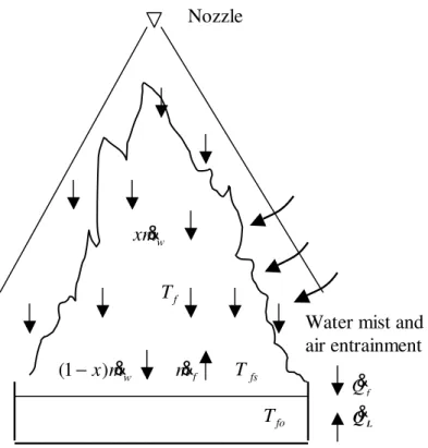
When water mist is discharged into a fire, as shown in Figure 1, some fine water drops, x &mw, are suspended in the flame and others, (1-x)m&w, penetrate through the flame
and reach the fuel surface. Water drops that are suspended in the flame absorb the heat from the flame and the heat released from the combustion of the fuel is used to heat the fuel-air mixture, and water droplets. The energy balance in the flame can be given as:
)) ( ) ( ( ) ( ) ( f fs f pa f a w vw pwL wp w pwv f wp pf f c f H m C T T m C T T xm L C T T C T T
m& ∆ = & − +φ& − + & + − + − (1) where, it is assumed that the flame has a uniform temperature, Tf, and the thermal capacities, Cp, of the fuel, air and water are not changed with temperature. The burning rate of the fuel, m&f , is equal to the rate of fuel vaporization, and x is the fraction of total discharged water mist (m& ) that is involved in flame cooling.w φ is the mass air to fuel ratio. It is larger than the stoichiometric ratio of the fuel-air mixture, because a pool fire is a typical diffusion flame, the air entrained into the flame is more than the amount that is required to burn the fuel gases, and also the discharge of water spray brings extra air into the flame.
The fire can be extinguished, when water mist cools the reaction zone to below the limiting adiabatic flame temperature, resulting in the termination of the combustion
reaction of the fuel-air mixture. For most hydrocarbons and organic vapours, this lower adiabatic temperature limit is approximately 1600 K (1327oC) [20].
Water drops that reach the fuel surface cool the fuel. The fire can also be extinguished, as the rate of supply of fuel vapour or burning rate is reduced due to the cooling and could not be sufficient enough to support the flame. The energy balance on the fuel surface at the fire point is [21]:
L E f vf c c H L m Q Q f
S=( ∆ − )& + & − & (2) where the fraction fc corresponds to the maximum fraction of the heat of combustion that the flame can lose to the fuel without self extinction. Q& is the rate of external heatE
transferred to the fuel and can be ignored in the local fire suppression application. Q& isL
the heat loss from the fuel, including heat loss to the open space through radiation, to the depth of the fuel through heat conductance, and to water droplets:
) ) ( ( ) 1 ( 4 vw w fs pw w fL fs L T q x m C T T L
Q& =εσ + & + − & − + (3)
where q& is heat loss from fuel surface to the depth of the fuel and can be given as [20]:fL
δ ) ( fs fo f fL T T k q& = − (4)
The energy balance on the fuel surface during suppression can be rewritten as: ))) ( ( ) 1 ( ( ) ( 4 w fs pw wv w fL fs f vf c c H L m T q x m L C T T f
S= ∆ − & − εσ + & + − & + − (5) For fuels with a high flash point, such as cooking oil, woods and solid fuels in electric equipment, their surface temperatures during burning are high (~400-500oC), leading to significant radiative heat losses from the fuel surface [22]. The heat loss to water is also significant when water drops hit and evaporate on the hot fuel surface. The fires can be extinguished with water mist through cooling the fuel surface.
For most freely-burning liquids, their surface temperature is close to, but slightly below their boiling point [20]. Therefore, for flammable liquid fuels that have a low boiling point (<100oC) or low surface fuel temperature, such as heptane, their radiative heat losses from the fuel surface and the heat losses to water droplets through evaporation can be ignored, and the heat losses from the fuel surface is simplified as:
) ( ) 1 ( w pw fs w fL L q x m C T T
Q& =& + − & − (6)
)) ( ) 1 ( ( ) (fc Hc Lvf mf qfL x mwCpw Tfs Tw
S = ∆ − & − & + − & − (7)
Equation (7) suggests that if the fuel surface temperature is low in suppression, it is very difficult to extinguish the fire through cooling the fuel surface, as heat loss from the fuel surface is much smaller than the heat gained from the flame.
The energy balance equations (1) and (5) for both flame and fuel surface also suggest that the burning rate of the fuel related to the fuel property and water mist discharge is an important parameter to determine how the fire is extinguished. It can be given as [20]: vf L f f L Q Q m & & & = − (8)
where Q&L is the heat loss from the fuel and given in Equation (3). Q&f is the rate of heat
transferred to the fuel surface from the flame. It consists of conductive heat transfer from the container, and convective and radiation heat transfer from the flame [23]:
rad conv cond
f q q q
Q& = & + & + & (9)
where D T T k q&cond =4 1( cw− fs) (10) ) ( 2 f fs conv k T T q& = − (11) )) exp( 1 )( ( 4 4 4 3 T T k D k q&rad = f − fs − (12)
During fire suppression in real applications, the size of the container is large or the fuel is not contained. The conductive heat transfer from the container to the fuel is limited and can be ignored, and the Equation (9) is rewritten as:
rad conv
f q q
Q& = & + & (13)
Combining equations (6) and (13), the burning rate for a flammable fuel is:
vf w fs pv w fL rad conv f L T T C m x q q q
m& = (& + & )−(& +(1− ) & ( − )) (14)
Combining equations (3) and (13), the burning rate for fuels with a high surface temperature is given as:
vf fs vw w fs pw w fL radi conv pw pwv w wp pwL vw vf a pa fs pf c w L T L T T C m x q q q T C T T C L L T C T C H m x ( ( (1 ) ( ( ) ) ))) ) -1600 ( ) -( ) ) -1600 ( ) -1600 ( ( φ + − + − − + +εσ 4 × + + − − − ∆
= & & & &
& vf vw w pv w fL fs rad conv f L L T C m x q T q q m ( ) ( (1 ) ( (373 ) )) 4 + + − − + − +
= & & & &
& εσ
(15)
Equations (14) and (15) suggest that the burning rate of the fuel could be increased during fire suppression as the discharge of water mist enhances the heat convection between the flame and the fuel. The influence of cooling of water mist on the burning rate of flammable fuel is limited, because the heat loss from the fuel surface is limited, while for fuels with a high surface temperature, the cooling influence on the burning rate is significant.
3. WATER MIST CRITRIA REQUIRED FOR LOCAL APPLICATION WATER MIST
Six properties of water sprays were identified to be important for fire extinguishment [16]. According to features of local application water mist, these six properties can be further combined into three most important criteria: water flux density, spray coverage and momentum.
As indicated in Equations (1) and (4), the fire can only be extinguished if the water quantity discharged from an extinguisher is sufficient enough to cool the flame, or to cool the fuel below its fire point. For a flammable fuel that has a low surface temperature, the fire is extinguished mainly through cooling the flame. The critical water mist flux required, (x &mw), can be given by combining Equations (1) and (14):
vf w fs pw w fL radi conv wp pwv w wp pwL vw vf a pa fs pf c w L T T C m x q q q T C T T C L L T C T C H m x ( ( (1 ) ( ))) ) -1600 ( ) -( ) ) -1600 ( ) -1600 ( ( + − + − − × + + − − − ∆
= & & & &
& φ (16)
For the fuels with a high surface temperature, the fires can be extinguished through cooling the fuel surface and/or cooling the flame. The critical water mist flux required can be given by combining Equations (1) and (15) for cooling the flame, (x &mw), and by
combining Equations (5) and (15) for cooling the fuel surface, ((1− x &)mw):
) ( ) ( ) )( 1 ( ) 1 ( 4 w fs pw wv fL fs rad conv c c vf cw T T C L q T q q H f L m x − + + − + ∆ − = − & & & & εσ (18)
Equations (16) to (18) suggest that for the same size of fuel surface, it needs higher water flux to extinguish a flammable liquid fire than a fire with a high surface temperature, because its burning rate is less affected. The equations also indicate that the
optimum spray characteristics required change with the type of fire encountered. For flammable liquids, the spray with fine water mist has a better extinguishing performance than one with coarse droplets, as most of the small droplets suspend in the flame and cool the flame, while for the fuels with a high surface temperature, the coarse sprays have a better performance as more drops are able to reach the fuel surface and to cool the fuel. This is consistent with experimental observations [7, 16].
The water mist coverage (Aw) that is related to the distribution of water drops and
water density is the second important parameter for the local suppression. It is especially important to extinguish a flammable liquid fire, because if the spray coverage is not big enough to cover the entire fuel surface, the flame that is not directly attacked by water mist will not be extinguished. The flame can easily propagate on the fuel surface, once the water mist attack is moved away. The edge of the effective spray coverage is determined by the minimum water flux required for extinguishing a local fire and can be expressed:
2 ) 2 tan ( α π a L Aw = c (19)
The spray angle, α , is a designed parameter of a nozzle and could be changed with discharge pressure. ac is the coefficient for the effective spray coverage (< 1) and
determined by the minimum water flux required and changes with the fuel property.
The third criterion required for the extinguisher is spray momentum. It must be strong enough for fine droplets to penetrate the fire plume, and to reach the fuel surface. Water mist with low momentum will be carried away by the fire plume. The maximum upward velocity in a fire plume, ufmax , is achieved in the intermittent flame [24]:
2 . 0 max 1.9 c f Q u = & (20)
where Q&c is the convective heat release rate of the flame.
For the water mist extinguisher, the discharge distance between the nozzle and fuel surface is relatively short, and the evaporation of water droplets is limited before reaching the flame. The velocity of a water droplet can be described under non-evaporation conditions [25]: ) 33 . 0 exp( w g wo w d L u u ρ ρ = (21)
) ( 2 0 w w P u ρ ∆ = (22)
To avoid water mist being carried away by the fire plume, the water mist momentum must be at least equal in magnitude, and opposite in direction, to fire plume momentum: max f w u u ≥ (23) or 2 . 0 9 . 1 ) 33 . 0 exp( ) ( 2 c w g w w Q d L P u ≥ & ∆ = ρ ρ ρ (24)
Equation (24) suggests that water droplet penetration is mainly determined by discharge pressure, droplet size, discharge distance and fire size. It can be enhanced more efficiently by either increasing droplet size, or reducing the discharge distance to the fire plume than by increasing the discharge pressure.
4. EXPERIMENTAL APPARATUS AND PROCEDURE
The most common fires encountered are Class A (such as wood and paper), Class B (flammable liquid), Class C (electric fire) and Class K fires (cooking oil). They each have different flash point and auto-ignition temperatures. In the present study, five fuels, including vegetable cooking oil (a mix of canola and soybean oils), heptane, diesel, wood crib and energized target, are selected and used in the experiments. Table 1 shows the properties of these fuels. The burning rate listed is one without fire suppression.
Table 1. Properties of the fuels [20, 26, 27, 28]
Fuel Density, (kg/m3) Burning rate, m& ,∞ (kg/m2.s) Flash point, (oC) Auto-ignition point,(oC) Heat of combustion (MJ/kg) Heat of gasification, Lfv, (kJ/g) Heptane 675 0.101 -4 104 44.6 0.48 Diesel 876 0.034 86 103 42.4 0.769 Canola 930 232 330 Soybean 926 0.0043 282 445 39.5 Wood (Douglas fir) 450 0.013 13 1.82
For a water mist extinguisher in extinguishing multiple types of fires, the maximum water flux required, as suggested by the above analysis, is determined by the properties of
the most challenging flammable fuel that is designed to be encountered. In the present work, it is determined by the properties of heptane fuel and can be estimated from Equation (16): s m kg m x w 0.106 / 2 )) 373 -1600 ( 1 . 2 ) 298 -373 ( 2 . 4 2580 ( 101 . 0 ) 480 ) 298 -1600 ( 15 . 1 1 . 15 6 . 1 ) 300 -1600 ( 58 . 1 44600 ( = × + × + × − × × × − × − = & (25)
where it is assumed that the burning rate of heptane is not affected by the cooling of water mist due to its low surface temperature. The stoichiometric air/fuel ratio of heptane is 15.1 [29] and it is assumed that there exists extra 60 percent air required for stoichiometric burning of the fuel gases in the flame. Heat capacity of vaporized heptane, steam, air and water is given, respectively to be 1.58, 2.1, 1.15, 4.2 kJ/kg.K [29].
4.1 Prototype Water Mist Extinguishers
Spray performances (spray angle, spray coverage and flow rate, etc.) of seven types of commercially-available mist nozzles were evaluated under various operating conditions. Two nozzles were selected for prototype portable water mist extinguishers according to their spray characteristics.
The extinguisher consists of a cylinder, a hose assembly, a nozzle holder and a nozzle. The cylinder has a maximum capacity of 9.4 L of water. Water mist characteristics of two extinguishers are given in Table 2.
Table 2. Water Mist Characteristics of Two Extinguishers
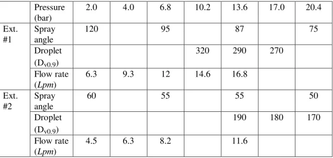
Pressure (bar) 2.0 4.0 6.8 10.2 13.6 17.0 20.4 Spray angle 120 95 87 75 Droplet (Dv0.9) 320 290 270 Ext. #1 Flow rate (Lpm) 6.3 9.3 12 14.6 16.8 Spray angle 60 55 55 50 Droplet (Dv0.9) 190 180 170 Ext. #2 Flow rate (Lpm) 4.5 6.3 8.2 11.6
Data on the droplet size (Dv0.9) and water flow rate of the two extinguishers are
provided by the nozzle manufacturer. The droplets produced by Extinguisher #1 (290 micron at 13.6 bar) are coarser than those generated by Extinguisher #2 (190 micron at
13.6 bar). Droplet sizes of both extinguishers become smaller with an increase in discharge pressure. Extinguisher #1 has a higher water flow rate (16.8 Lpm at 13.6 bar) than Extinguisher #2 (11.6 Lpm at 13.6 bar).
Changes of spray angles of two extinguishers with discharge pressure were recorded/measured by a digital camera and a digital video camera in the present work. Extinguisher #1 had 120 degrees of a spray angle at 2 bars, but with the increase in discharge pressure, the spray angle was reduced to 75 degrees at 20.4 bar. Extinguisher #2 had 60 degrees of a spray angle at 2 bars and it slightly decreased with the increase in discharge pressure.
4.2 Heptane and Diesel Fire Scenarios and Measurements
A 0.47 x 0.47 x 0.3 m high steel pan was used in the heptane and diesel fire experiments. The fuel depth in the pan was not less than 5 cm. The surface of the fuel layer was located 15 cm below the top edge of the pan, so that the fire could not be blown away by the discharge of water mist.
One thermocouple tree with three 26 gauge thermocouples was set up in the middle of the fuel pan. One thermocouple was located 2 cm below the fuel surface to measure the fuel temperature, and two thermocouples were located 3 cm and 13 cm, respectively, above the fuel surface to measure fire temperatures. One video camera was set up to obtain visual records of the fire extinguishment. The video was recorded at approximately 30 frames per second.
During the experiments, the liquid fuel was ignited manually by using a blow torch and the fire was allowed to burn freely for 1 min before water mist discharge. The water mist attack was made from one side only and the operator was not allowed to extend any part of his body past the edge of the test pan while fighting the fire.
4.3 Cooking Oil Fire Scenarios and Measurements
A commercial propane-fired deep fat fryer was used in the cooking oil fire extinguishment tests. The fryer had a frying area of 0.457 m x 0.457 m. The depth of the fryer was 0.457 m. During the experiments, the fryer contained 42 L of vegetable cooking oil (a mix of canola and soybean oils).
One thermocouple tree with four 26 gauge thermocouples was set up in the middle of the fryer. Two thermocouples were located 2.5 cm and 5 cm below the fuel surface to measure oil temperatures, and two thermocouples were located 5 and 10 cm above the fuel surface to measure fire temperatures. One video camera was set up to obtain visual records of the fire extinguishment.
During the experiments, the cooking oil in the fryer (0.228 m of depth) was heated to its auto-ignition temperature, and the fire was left to burn freely for 1 min before the
water mist discharge. The extinguisher’s nozzle was not extended over the front edge of the fryer during fire suppression. The heating source to the fryer remained on until the cooking oil fire was extinguished.
4.4 Wood Crib Fire Scenarios and Measurements
Wood cribs used in the fire experiments consisted of nominal 0.038 m x 0.038 m x 0.635 m long spruce. A total of 112 wooden sticks were arranged as the crib with 16 layers of 7 sticks. The crib is constructed upon an iron support frame and mounted on a weighing platform at a height of 0.39 m above the floor. A pan with the size of 0.53 m x 0.53 m x 0.1 m high and 2 L of n-heptane was placed centrally beneath the crib and acted as an ignition source.
The total mass of the crib was measured prior to the experiment. Heptane in the pan was then ignited manually and the crib allowed to burn until its mass was reduced to 55 percent of its original mass. Water mist was applied to the crib on its three sides, and top and bottom, using a continuous discharge. No discharge was directed at the back of the crib. After the crib fire was extinguished, the crib was left for 15 minutes and checked for possible re-ignition. One video camera was set up to obtain visual records of the fire extinguishment.
4.5 Class C Fire Scenarios and Measurements
Compared to other types of fire, the fire size associated with the electric equipment is relatively small [10]. The primary concern in using a portable water mist extinguisher for firefighting is that the discharge of water mist toward energized targets may produce a shock hazard to the user. In the present study, the impact of water spray on the leakage current under high applied voltage was investigated. No fires were involved in the experiments.
Figure 2 shows the experimental setup. A 60 Hz transformer (GE Electric) rated at 50 kV was used to supply the high voltage. A water mist nozzle was placed 0.38 m away from the centre of a circular copper target with a diameter of 0.25 m. A metallic cylinder, containing 50 L of pressurized water, was then connected to the nozzle. The water mist system, including the nozzle, pipe and cylinder, was connected to the high voltage secondary of the transformer, and the electric potential between the nozzle tip and the copper target was maintained around 50 kV during tests. The metallic cylinder was placed on a wooden stand to isolate it from the ground. All metallic connectors, including the circular electrode, had rounded edges to prevent the inception of partial discharge.
During the experiments, the discharge of water mist was activated first for 10 s before the transformer was turned on. The voltage was then increased in steps of 10 kV, with 10 s of water mist discharge at each step, until 47.5 kV. At the maximum voltage of 47.5 kV, water mist discharge continued for 30 – 50 s. The current in the primary
winding of the transformer, as well as the leakage current under different discharge pressures, were measured at each step by two battery-operated multimeters.
5 RESULTS AND DISCUSSION
5.1 Spray Performance of the Extinguishers
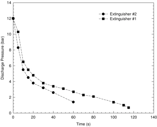
The discharge pressure of both extinguishers used in the experiments was 12 bar. Figure 3 shows that their discharge pressures decline very quickly with time, particularly in the initial discharge period in which they drop from 12 bar to 5.2 and 5.8 bar, respectively in 15 s. After the initial discharge period, the decrease in discharge pressure slows down.
The changes in local water flux density (kg/m2.s) of the two extinguishers at three different discharge distances (0.3, 0.5 and 0.7 m) with time were investigated in the experiments. Nine sampling cups with 3.8 cm diameter, starting from the spray centre, were placed on the ground. The interval distance between the cups was 5 cm. Water was collected and measured after each 15 s continuous discharge until the water in the extinguisher ran out.
Figure 4 shows changes in the local water flux density distribution (kg/s.m2) of Extinguisher #1 with discharge time, when the discharge distance from the nozzle tip to the floor was 0.5 m. The water density at the spray centre was high in the initial discharge period (0-15 s). With an increase in discharge time, the water density quickly dropped and tended to be uniform in the spray coverage. The water density at the edge of the measured spray coverage (radius ~ 0.40 m) was higher than one required for extinguishing a heptane fire during 60 s of discharge.
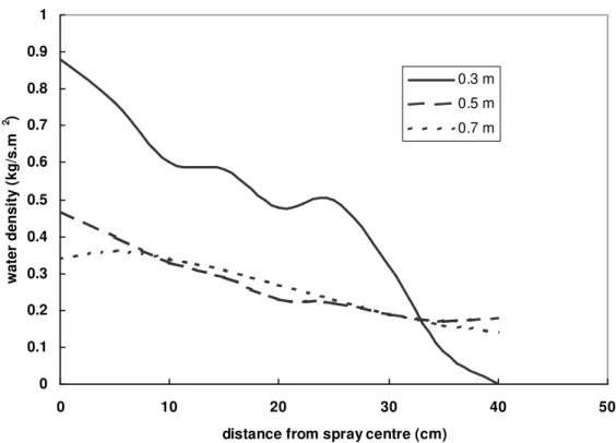
Figure 5 shows the changes of the local water density of Extinguisher #1 with changes in the discharge distance during initial discharge (0 – 15 s). The water density was very high but the spray coverage was small at 0.3 m of the discharge distance. As the discharge distance increased, the local water density was reduced but the spray coverage increased. The water density distributed in the coverage area had no significant change with an increase in the discharge distance from 0.5 m to 0.7 m.
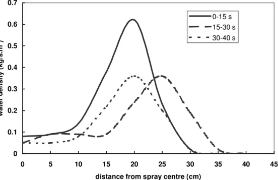
Extinguisher #2 had a different water distribution pattern from Extinguisher #1. As shown in Figure 6, its spray coverage was smaller than Extinguisher #1. The peak local water density was higher than Extinguisher #1 but not located at the spray centre. The local water density around the spray centre was lower than one required for extinguishing a heptane fire. With an increase in discharge time, the peak water density further moved away from the spray centre. Figure 7 shows that its spray coverage increases but local water density is substantially reduced with an increase in the discharge distance.
These results suggest that the spray performance of an extinguisher is significantly changed with discharge time and distance. The initial discharge period (0-15 s) is a critical
period for a water mist extinguisher to extinguish fires because both the discharge pressure and water flow rate are relatively high in this discharge period. Also, the selection of an appropriate discharge distance is very important for fire suppression, because it determines the spray momentum, water flow density and the spray coverage area in suppression.
5.2 Heptane and Diesel Fires
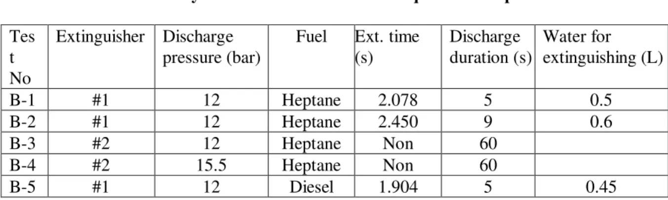
A total of 5 full-scale fire experiments were conducted to study the effectiveness of the two extinguishers against heptane and diesel fires. The operator who wore protective clothing stood 1.1 m away from the pan to activate the extinguisher. The discharge distance from the nozzle to the pan was approximately 0.5 to 0.7 m. Experimental conditions and results are listed in Table 3. The fire extinguishing time was determined, based on the image record of the video.
Table 3. Summary of Results in Flammable Liquid Fire Experiments
Tes t No
Extinguisher Discharge pressure (bar)
Fuel Ext. time (s) Discharge duration (s) Water for extinguishing (L) B-1 #1 12 Heptane 2.078 5 0.5 B-2 #1 12 Heptane 2.450 9 0.6 B-3 #2 12 Heptane Non 60 B-4 #2 15.5 Heptane Non 60 B-5 #1 12 Diesel 1.904 5 0.45
Extinguisher #1 extinguished heptane fires at approximately 2.078 s to 2.45 s in two tests. The water quantities used were approximately 0.5 ~ 0.6 L. No re-ignition was observed. The decline in discharge pressure did not affect the effectiveness of Extinguisher #1 as the fire was extinguished in a very short discharge period. The effectiveness of Extinguisher #1 in extinguishing the heptane fires was consistent with its spray characteristics and corresponding requirements presented in theoretical analysis.
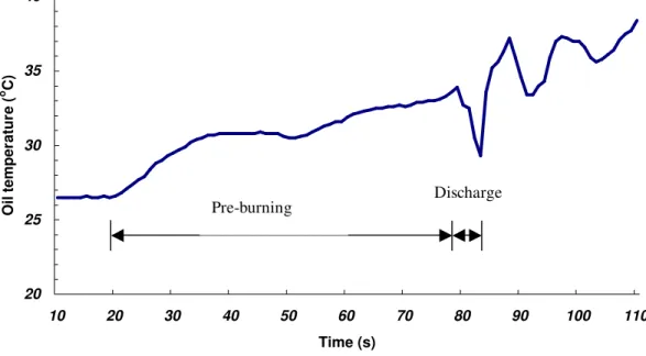
Figure 8 shows variation of the fuel temperature with time that was measured at 2cm below the heptane fuel surface in Test B-1. In the 1 min pre-burning period, the heptane fuel temperature increased from 26.5oC to 34oC. The fuel temperature had a slight increase at the beginning of water mist discharge and then quickly dropped to 29oC as the fire was extinguished. The testing results confirm theoretical analysis in the present work that the flammable fuel has a lower temperature during suppression, and the heat losses from the fuel is very limited. The burning rate of heptane can then be approximately given as: vf rad conv f L q q
This equation suggests that although water mist could not effectively cool the heptane fuel, its burning rate is still affected by the presence of water mist in the flame through heat transfer to the fuel from the flame by heat convection and radiation. This can be observed from its extinguishing process recorded from a series of instantaneous images. As shown in Figure 9, the extinguishment of a heptane fire could be divided into five phases. In phase I, from 0 ms to 612 ms (figures 9a to 9e), the flame height was reduced but the flame was enlarged radially under water mist attack as hot gases were pushed toward the fuel surface, increasing heat convection between the flame and the fuel and then resulting in an increase in fuel burning rate, as indicated in Equation (26). In phase II, from 612 ms to 952 ms (figures 9e to 9g), with continuous water mist discharge, the flame near the fuel surface was destabilised and the fire plume was separated from the fuel surface. However, the fire size continued to increase and a large flare-up was generated as unburned fuel vapour escaped from the water spray, burnt and expanded in the air. Fuel and water vapour were observed near the fuel surface (Figure 9g). In phase III, from 952 ms to 1496 ms (Figure 9g to 9j), the size of the flare-up gradually reduced, as the fuel/air mixture burnt out and less fuel vapour was supplied from the fuel. In phase IV, from 1496 ms to 1738 ms (Figures 9j to 9l), the flame flashed back toward the fuel surface, its size increased and the flame colour turned from yellow to white. However, large water spray coverage prevented the flame from touching the fuel surface. In phase V, from 1738 ms to 2078 ms (Figures 9l to 9o), the fire was extinguished as the flame above the fuel totally burnt out.
The changes in flame size during suppression are illustrated in Figure 10, in which the ratio of the flame size is defined as the ratio of the flame size during suppression to the non-suppressed flame size at the end of the free burning period. The flame sizes were calculated approximately from the images recorded from the video camera. It is clearly shown that under water mist attack, the heptane flame was enlarged and the maximum flare-up volume generated could be nearly 50 times larger than in the non-suppressed fire. Figure 11 shows the flame temperatures measured at two locations above the fuel surface. After a certain burning period, the flame temperature at 13 cm above the fuel surface reached approximately 800oC and tended to be steady, while the flame temperature at 3 cm above the fuel surface reached to approximately 650oC and then decreased, because its flame region was located 12 cm below the top edge of the pan, and fresh air from outside the flame was difficult to reach this region. Oxygen available for combustion was reduced as the combustion continued, resulting in a lower burning rate and lower flame temperature. Under water mist attack, the flame near the fuel surface is more easily destabilised and extinguished, resulting in the separation of the fire plume from the fuel surface, as observed in the experiment.
The operator also tried to use Extinguisher #2 to extinguish the heptane fire under the same testing conditions and procedures as using Extinguisher #1. Under water mist attack, the heptane flame shape was changed but the fire plume was not separated from the fuel surface and no fire flare-up was generated. With an increase in discharge duration, both pressure and flow rate quickly decreased. The fire was not extinguished in
1 min of discharge. When the discharge pressure of Extinguisher #2 was increased to 15.5 bar from 12 bar, the heptane flame was still not extinguished after 1 min of discharge, although both the discharged water flow rate and the spray momentum were increased.
As shown in the spray experiments, the water density of Extinguisher #2 was not distributed uniformly. Its local water density around the spray centre was lower than one required for extinguishing the heptane fire (0.106 kg/m2.s). Its effective spray coverage was also smaller than Extinguisher #1. Any residual flame or hot object near the fuel surface, such as the pan edge that was not be covered by water spray, could keep the flame in the fuel pan. This may explain why Extinguisher #2 could not extinguish the heptane fire.
In Test B-5, Extinguisher #1 was used to extinguish a diesel fire. The fire was extinguished at approximately 1.904 s with approximately 0.45 L of water. Compared to heptane fires, the diesel fire was extinguished more quickly. This is consistent with the analysis in the present work (Equation (15)): the diesel fuel has a higher surface temperature than heptane fuel and its burning rate is affected by the cooling of the fuel by water mist, resulting in quick extinguishment.
The extinguishing process of diesel fires also showed some differences from heptane fires. As shown in instantaneous flame images in Figure 12, the extinguishment of diesel fire could be divided into four phases. During phase I, both the flame height and fire size were reduced under water mist attack (Figures 12a to 12d), and then the fire size grew in phase II (Figures 12d to 12f). The flame was separated from the fuel surface and a large fire flare-up was generated in phase III (Figures 12g to 12i). The fire flare-up generated was smaller than that observed in a heptane fire extinguishment as the burning rate of diesel or fuel vapour generated was smaller than the heptane’s. In phase IV (Figures 12j to 12l), the fire was extinguished as the fire flare-up disappeared and residual flame near the fuel surface was extinguished. No flame flash back was observed in the diesel fire extinguishment. The water vapour was observed above the oil surface after the fire was extinguished (Figure 12l), as water mist directly hit onto hot diesel fuel.
Figure 13 shows the changes of diesel fire size with time during suppression. Under water mist attack, the diesel flame was also enlarged but its maximum size was much smaller than the heptane fuel, because it generated less volatile fuel vapour.
5.3 Cooking Oil Fires
Five full-scale experiments involving two extinguishers were conducted. During the experiments, the cooking oil in the fryer (0.228 m deep) was heated continuously at a rate of 4 – 8oC/min and it auto-ignited at the temperature of 368oC. After auto-ignition, the fire was left to burn freely for 1 min with the heating source remaining on. The oil temperature was further heated to 396oC. At the end of the free burning period, the operator stood 1.1 m away from the fryer with the nozzle located near the edge of the
fryer and activated a full water mist discharge. Testing conditions and results are listed in Table 5.
Table 5. Summary of Results in Cooking Oil Fire Tests
Test No Extinguisher Discharge pressure (bar) Water in cylinder (L)
Ext. time (s) Discharge duration (s) K-1 #1 12 9 2.652 20 K-2 #1 12 6 3.0 15 K-3 #1 8.6 9 19.0 27 K-4 #2 12 9 8.0 22 K-5 #2 10.3 9 10.0 20
Extinguisher #1 at a discharge pressure of 12 bar extinguished the cooking oil fire at approximately 2.65 s. No re-ignition of the cooking oil was observed. When water quantity in the cylinder of the extinguisher was reduced from 9 L to 6 L, its extinguishing performance was not affected. With the reduction in discharge pressure from 12 bar to 8.6 bar, however, the extinguishing time increased to 19 s, as the water flow rate and spray momentum were significantly reduced.
The experimental results also showed that under the same testing conditions, Extinguisher #2 was able to extinguish the cooking oil fire but its extinguishing time was longer than that using Extinguisher #1. This suggests that although Extinguisher #2 could not extinguish the heptane fire, it was still capable of extinguishing cooking oil fires due to different extinguishing mechanisms and different water mist characteristics required, as analysed in the present work.
Figure 14a shows variation of oil temperatures during suppression that were measured at two depths of the oil. The oil temperatures were not immediately cooled down with the discharge of water mist, but continued to increase a few more degrees until the fire was extinguished. The drops in oil temperature were significant after the fire was extinguished, as water mist directly touched the hot oil. The fuel temperature in the deep depth of the oil was a few degrees higher than that close to the oil surface during the cooling period. Figure 14b shows that although fire temperatures above the oil surface were high during the free burning period, they quickly decreased with the discharge of water mist.
The cooking oil has a lower burning rate but a very high surface temperature. Cooling the oil surface effectively reduces the burning rate, and much less water is required to extinguish cooking oil fires. However, it took a longer time to extinguish cooking oil fires than heptane fires. This could be explained from the generation of oil’s burning rate in Equation (15). Unlike the ignition process for heptane and diesel fires in the tests, the cooking oil was heated to auto-ignite and further heated to a temperature higher than its auto-ignition point during the free burning. During water mist discharge, the oil surface was cooled down but the oil below its surface was still hot. The oil itself
was not an energy sink but an energy supply for maintaining the flame growing. In order to extinguish a cooking oil fire, a longer discharge time was needed to cool the oil and to reduce the rate of evolution of combustible vapour from the oil.
Figure 15 shows that the extinguishing process of a cooking oil fire is different from either heptane or diesel fires. Its extinguishment could be divided into three phases. In phase I from 34 ms to 952 ms (Figures 15a to 15e), the flame size continuously increased under water mist attack. This resulted from the increase in heat transfer between the flame and the oil under water mist attack, as observed in heptane and diesel fires. Also, as water droplets hit very hot oil, their explosive vaporization carried extra fuel vapour into the flame above the oil surface. The flame reached its maximum size at 952 ms. In phase II from 1632 to 2632 ms (Figures 15g to 15k), the fire plume was separated from the oil and a large amount of water vapour was generated, as the water drops directly touched very hot oil. The fire size above the oil surface was then gradually reduced until the fire was extinguished.
Figure 16 shows the changes of oil fire size with time during suppression. Under water mist attack, the size of the cooking oil flame continuously increased and its maximum volume was nearly 80 times larger than in the non-suppressed fire. The changes in fire size were even larger than the heptane fire due to different suppression process.
5.4 Wood Crib Fires
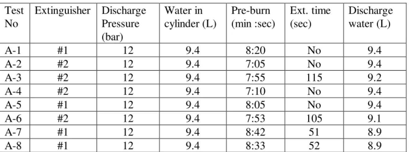
A total of 8 full-scale experiments were conducted to extinguish wood crib fires. Testing conditions, sequence and results are summarized and listed in Table 6.
Table 6. Summary of Results in Wood Crib Fire Tests
Test No Extinguisher Discharge Pressure (bar) Water in cylinder (L) Pre-burn (min :sec) Ext. time (sec) Discharge water (L) A-1 #1 12 9.4 8:20 No 9.4 A-2 #2 12 9.4 7:05 No 9.4 A-3 #2 12 9.4 7:55 115 9.2 A-4 #2 12 9.4 7:10 No 9.4 A-5 #1 12 9.4 8:05 No 9.4 A-6 #2 12 9.4 7:53 105 9.1 A-7 #1 12 9.4 8:42 51 8.9 A-8 #1 12 9.4 8:33 52 8.9
The wood crib fires grew quickly with the assistance of the heptane fire that was placed centrally beneath the crib. The heptane fire self-extinguished after 2 min burning as the fuel in the pan was exhausted. It took approximately 7 to 9 min for the crib to be reduced to 55 percent of its original mass.
In the experiments, both Extinguishers #1 and #2 extinguished the wood crib fire. However, its extinguishing performance was heavily dependent on the tactics of water mist attack. For Tests A-1 to A-5, water mist was applied randomly on the top and the sides of the crib, chasing flames without making sure that the fire attacked was extinguished. A large amount of water was wasted in the random discharge. Also, the spray momentum and flow rate were quickly reduced in suppression as the discharge pressure of the extinguishers declined. The flame located in the center and back of the crib was especially difficult to extinguish. Among Test A-1 to Test A-5, only the crib fire in Test A-3 using extinguisher #2 was extinguished.
For Tests A-6 to A-8, the water mist spray was applied systematically, starting from underneath the crib and then side by side. The fire on the top of the crib was attacked last. Water mist discharge was maintained for a minimum of 10 s on each side of the crib, making sure the fire on that side was extinguished before moving on to the other side. Figure 17 shows the extinguishing process of the wood crib fire with Extinguisher #1. Unlike liquid fuel fires, the wood crib fire size was reduced under water mist attack and no fire flare-up was generated. Both Extinguishers #1 and #2 successfully extinguished the crib fires and no re-ignition was observed. The extinguishing time using Extinguisher #1 was approximately 51 s, while Extinguisher #2 extinguished the crib fire at 1 min 45 s due to its low flow rate. However, the water quantity of the two extinguishers used in extinguishment was almost the same at around 9 L. The amount of water required was much larger than those for a liquid fire, because the wood crib fire was a three dimensional fire.
Basic requirements to extinguish a wood crib fire for a water mist extinguisher include: sufficient spray momentum allowing the water droplet to penetrate into the center of the wood crib and to reach the back of the crib that is not directly attacked in suppression, and sufficient water to extinguish the wood fire in each side of the crib. It has no specific requirement for spray coverage because once the crib fire is extinguished, it is difficult for the flame to propagate back and to re-ignite the wood. It also has a less strict requirement for water density distribution as long as a sufficient amount of water is applied to cool the fuel. As a result, both extinguishers, although they have different water mist characteristics, were able to extinguish the wood crib fire.
5.5 Class C Fires
Test results showed that there was no electrical breakdown between the nozzle tip and energized target under applied high voltages, when water mist was discharged toward the energized target for the full test duration. The leakage current generated varied with the applied voltage, the nozzle used, the discharge distance between the nozzle and the energized target, and the water mist discharge conditions.
Figure 18 shows the variation of leakage current generated by two nozzles with applied voltages, when the nozzle was placed 0.38 m from the centre of the energized target and the discharge pressure of water mist was maintained at 12.24 bar. The leakage
current increased with the increase in applied voltage. The leakage current generated by Extinguisher #1 was lower than that by Extinguisher #2. The maximum leakage currents produced by two extinguishers at 47.5 kV were 145 and 158µA, respectively. This may be explained from the fact that although both the droplet size and total water flow rate of Extinguisher #1 were larger than those produced by Extinguisher #2, its water density was distributed more uniformly and its maximum local water density was smaller than that produced by Extinguisher #2.
In order to further study the impact of water density on the production of leakage current, the variation of leakage current with a change in discharge pressure for the two nozzles was investigated, when the discharge of water mist was maintained for 30 s –50 s at a maximum voltage of 47.5 kV. As shown in Figure 19, with a reduction in discharge pressure or water density, the leakage currents generated by both nozzles were decreased. The leakage currents of Extinguisher #1 were still lower than those of Extinguisher #2 under all discharge pressure. This also suggests that a potential shock hazard to the user would not increase during operation of a water mist extinguisher, as its water density substantially reduces with an increase in discharging time.
The impact of discharge distance on the production of the leakage current was also studied in the experiments. With the reduction in discharge distance, both the conductivity of the water spray and water density that hit onto the energized target were increased. As shown in Figure 20, the leakage current generated at a discharge distance of 0.19 m was substantially higher than that at the distance of 0.38 m, when the discharge pressure of Extinguisher #2 was maintained at 12.24 bar (180 psi). The maximum leakage current at 47.5 kV was increased from 158 µA at 0.38 m distance to 235 µA at 0.19 m distance. However, the leakage current did not cause an electrical breakdown between the nozzle tip and the energized target.
These experimental results showed that the maximum leakage currents produced by both extinguishers in the experiments were approximately one third (0.38 m distance) and one half (0.19 m), respectively, below the threshold of involuntary startle reaction (500 µA) for electric current through the human body. The limit is set up by both the International Electrotechnical Commission (IEC) and Underwriters’ Laboratories (UL) [30]. Therefore, the use of either extinguisher should not pose a shock hazard to the user.
6 CONCLUSION
Both theoretical analysis and experimental results showed that the extinguishing mechanisms and process as well as water mist characteristics required change with the types of fires encountered. The liquid pool fire that has a low surface temperature was extinguished by water mist mainly through flame cooling, while the liquid pool fire that has a high surface temperature was extinguished mainly through both flame and fuel surface cooling. The fires were enlarged in suppression, as the discharge of water mist increased the heat transfer between the flame and the fuel surface. A fire flare-up was generated as the fire plume was separated from the fuel surface, and the volatile fuel
vapour burned and expanded in the air. The solid fuel fire, such as a wood crib fire, was mainly extinguished through cooling the fuel surface. A long extinguishing time and high water quantity were required to extinguish a wood crib fire, because it was a three dimensional fire. Leakage currents generated in the water mist discharge onto an energized target enhanced with an increase in water mist flux density and in discharge distance to the target. Under the experimental conditions in the present study, the maximum leakage currents produced by both extinguishers were less than half that of the limit of involuntary startle reaction for electric current through the human body. One water mist fire extinguisher was successfully developed through this work to extinguish multiple types of fires, including flammable liquid fires, cooking oil fires, and wood crib fires and fires in electric equipment. The water mist characteristics required for a successful portable water mist extinguisher were water flux density, spray coverage and spray momentum.
7 ACKNOWLEDGEMENTS
The study was conducted under a joint research project between CAFS Unit, Inc. and the National Research Council of Canada. The authors would like to acknowledge the assistance of Mr. Ping-Li Yen of CAFS Unit, Inc. in this work. The authors would also like to thank Dr. Alexander Bulinski, Dr. Soli Bamji, Mr. Doug Mclntyre, and Mr. Daniel St-Jean of NRC, Institute for National Measurement Standards, for their contributions to this project. Finally, the authors would like to thank Professor Drysdale for his discussion and suggestions on the paper.
8 REFERENCES
1. Gately, B. “Portable Value,” Fire Prevention, May 2000
2. Martiny, T., “Portable Importance,” Fire Prevention, May 2003
3. Bonnett, D., “Portable Performance,” Fire Engineering Journal, August 2002,
4. Cortina, T., “Update on AFFF Environments Issues,” Workshop on Fire Suppression Technologies, Mobile, Alabama, February 2003,
5. Su, J. Z., Kim, A. K., "Suppression of pool fires using halocarbon streaming agents,"
Fire Technology, 38, (1), January, pp. 7-32, January 01, 2002.
6. Braidech, M.M., Neale, J.A., Matson, A.F. and Dufour, R.E., "The Mechanisms of Extinguishment of Fire by Finely Divided Water," Underwriters Laboratories Inc. for the National Board of Fire Underwriters, NY, p.73, 1955.
7. Rasbash, D.J. and Rogowski, Z.W., "Extinction of Fires in Liquids by Cooling with Water Sprays," Combustion and Flame, Vol. 1, 1957.
8. Rasbash, D.J., Rogowski, Z.W. and Stark, G.W.V., "Mechanisms of Extinction of Liquid Fuel Fires with Water Sprays," J. of Combustion and Flame, Vol. 4, 1960, pp. 223-234.
9. Liu, Z. and Kim, A. K, “A Review of Water Mist Fire Suppression Systems – Fundamental Studies,” J. of Fire Protection. Engineering, 10 (3), 2000, pp 32-50 10. Liu, Z. and Kim, A. K., “A Review of Water Mist Fire Suppression Systems –
11. Notarianni, K. A., “Water Mist Fire Suppression Systems,” Proceedings of Technical Symposium on Halon Alternatives, Society of Fire Protection Engineers and PLC Education Foundation, Knoxville, TN, 1994.
12. Liu, Z., Kim, A. K., Carpenter, D., Kanabus-Kaminska, J. M. and Yen, P. L., “Extinguishment of Cooking Oil Fires by Water Mist Fire Suppression Systems,” Fire Technology, 40, (4), pp. 309-333, 2004
13. Mawhinney, J.R. and Richardson, J.K., "A Review of Water Mist Fire Suppression Research and Development," Fire Technology, Vol. 33, No. 1, 1997, pp. 54-90. 14. Mawhinney, J.R., "Engineering Criteria for Water Mist Fire Suppression Systems,"
Proceedings: Water Mist Fire Suppression Workshop, NIST, Gaithersburg, MD, 1993, p. 37.
15. Mawhinney, J.R., "Water Mist Fire Suppression Systems: Principles and Limitations," International Conference on Fire Protection in the HVDC Industry, Vancouver, Canada, 1995.
16. Rasbash, D. J., “The Extinction of Fire with Plain Water: A Review,” 1st International Symposium on Fire Safety Science, pp. 1145-1164, 1985
17. Heskestad, G., “The Role of Water in Suppression of Fire: a Review,” J. of Fire & Flammability, Vol. 11, p.254, Oct. 1980
18. Beyler, C., “A Unified Model of Fire Suppression,” J. of Fire Protection Engineering, 4 (1), 1992, pp 5-16
19. ULC, “9 L Water Spray Fire Extinguisher (Stored Pressure Type),” Underwriters’ Laboratories of Canada, CEx474, 1998.
20. Drysdale, D., “An Introduction to Fire Dynamics,” John Wiley and Sons, New York, 1985.
21. Rasbash, D. J., “Relevance of Firepoint Theory to the Assessment of Fire Behaviour of Combustible Materials,” International Symposium on Fire Safety of Combustible Materials, Edinburgh University, pp. 169-178, 1976
22. Grant, G., Brenton, J., and Drysdale, D., “ Fire Suppression by Water Sprays,” Progress in Energy and Combustion Science, Vol. 26 pp. 79-130, 2000.
23. Blinov, V. I., and Khudiakov, G. N., “The Burning of Liquid Pools,” Doklady Akademi Nauk SSR, 113, 1094, 1957,
24. McCaffrey, B. J., ‘Purely Buoyant Diffusion Flames: Some Experimental Results,’ National Bureau of Standards, NBSIR 79-1910, 1979,
25. Williams, A. “Combustion of Sprays of Liquid Fuels,” Unwin Brothers Limited, UK, 1976.
26. Koseki, H., Natsume, Y. and Iwata, Y., “Combustion of High Flash Point Materials,” Proceedings: 7th International Fire and Materials Conference, pp. 339-349, San Francisco, January 2001.
27. Hui, Y. H., "Bailey's Industrial Oil & Fat Products, Vol. 2, Edible Oil & Fat Products: Oils and Oil Seeds," John Wiley & Sons, Inc., New York, 1996.
28. Nam, S. “Application of Water Sprays to Industrial Oil Cooker Fire,” 7th International Symposium on Fire Safety Science, Massachusetts, USA, 2002.
29. Appendices B and C of The SFPE Handbook of Fire Protection Engineering, Third Edition, National Fire Protection Association, Quincy, MA 02269, 2002
30. Reilly, J. P., “Electrical Stimulation and Electropathology,” Cambridge University Press, New York, USA, 1992
24 f m& f T fs T fo T w m x & w m x &) 1 ( −
Water mist and air entrainment
Figure 1. Schematic representation of interaction between a fire and water mist
Figure 2. Schematic of experimental set-up for measuring the leakage current when water mist is discharged towards an energized target associated with Class C fires
f
Q&
L
Q&
Figure 3. Variation of discharge pressures of two extinguishers with time Time (s) 0 20 40 60 80 100 120 140 Discharge Pressure (bar) 0 2 4 6 8 10 12 14 Extinguisher #2 Extinguisher #1
0 0.05 0.1 0.15 0.2 0.25 0.3 0.35 0.4 0.45 0.5 0 5 10 15 20 25 30 35 40 45
distance from spray centre (cm)
water density (kg/s.m 2 ) 0-15 s 15-30 s 30-45 s 45-60 s 0 0.1 0.2 0.3 0.4 0.5 0.6 0.7 0.8 0.9 1 0 10 20 30 40 50
distance from spray centre (cm)
water density ( kg/s.m 2 ) 0.3 m 0.5 m 0.7 m
Figure 4. Variations of water density of Extinguisher #1 with changes in discharge time and location when discharge distance is 0.5 m from the floor.
Figure 5. Variations of water density of Extinguisher #1 with changes in discharge distance, during initial discharge period (0 - 15 s)
0 0.1 0.2 0.3 0.4 0.5 0.6 0.7 0 5 10 15 20 25 30 35 40 45
distance from spray centre (cm)
water density (kg/s.m 2 ) 0-15 s 15-30 s 30-40 s -0.2 0 0.2 0.4 0.6 0.8 1 1.2 1.4 1.6 1.8 0 10 20 30 40 50
distance from spray centre (cm)
water density ( kg/s.m 2 ) 0.3 m 0.5 m 0.7 m
Figure 6. Variations of water density of Extinguisher #2 with changes in discharge time and location when discharge distance is 0.5 m from the floor
Figure 7. Variation of water density of Extinguisher #2 with changes in discharge location and distance when discharge time is varied from 0 to 15 s
Figure 8. Variation of heptane fuel temperature during suppression with Extinguisher #1 20 25 30 35 40 10 20 30 40 50 60 70 80 90 100 110 Time (s) Oil temper atur e ( o C) Pre-burning Discharge
29 (a) 68 ms (b) 272 ms (c) 340 ms (d) 408 ms (e) 612 ms (f) 748 ms (g) 952 ms (h) 1224 ms (i) 1360 ms (j) 1496 ms (k) 1534 ms (l) 1738 ms (m) 1874 ms (n) 1942 ms (o) 2078 ms
Figure 10. Variation of ratio of the heptane flame size during suppression with Extinguisher #1 Time (ms) 0 200 400 600 800 1000 1200 1400 1600 1800 2000 2200 Rat io o f Flame Siz e in S u ppress io n (F s /F i ) 0 5 10 15 20 25 30 35 40 45 50
0 100 200 300 400 500 600 700 800 900 10 20 30 40 50 60 70 80 90 100 110 Time (s) Fire t emperatur e ( o C) 3 cm 13 cm Pre-burning Discharge
(a) 34 ms (b) 136 ms (c) 238 ms
(d) 680 ms (e) 918 ms (f) 1156 ms
(g) 1292 ms
(h) 1496 ms (i) 1564 ms
(j) 1632 ms (k) 1768 ms (l) 1904 ms
Figure 13. Variation of ratio of the diesel flame size during suppression with Extinguisher #1 Time (ms) 0 200 400 600 800 1000 1200 1400 1600 1800 2000 2200 Ratio of F lame Size in Sup pr ession (F s /Fi ) 0 2 4 6 8 10 12 14 16
34 Time (s) 300 350 400 450 500 550 Oi l T emperatur e ( o C) 280 300 320 340 360 380 400 420 25.4 mm deep 50.5 mm deep
fire free burning period discharge period
Time (s) 300 350 400 450 500 550 Temper ature ( o C) 0 100 200 300 400 500 600 700 800
50 mm above oil surface 100 mm above oil surface
fire free burning period discharge period
Figure 14b. Variation of oil fire temperatures during suppression with Extinguisher #1
Figure 14a. Variation of cooking oil temperatures during suppression with Extinguisher #1
(a) 34 ms (b) 170 ms (c) 374 ms
(d) 612 ms (e) 952 ms (f) 1292 ms
(g) 1632 ms (h) 1972 ms (i) 2312 ms
(j) 2482 ms (k) 2652 ms
Figure 16. Variation of ratio of the cooking oil flame size during suppression with Extinguisher #1 Time (ms) 0 200 400 600 800 1000 1200 1400 1600 1800 2000 2200 2400 2600 2800 Ratio of Fla me Size in Supp ression (F s /Fi ) 0 10 20 30 40 50 60 70 80 Phase I Phase II
(a) 1 s (b) 25 s
(c) 40 s (d) 50 s
Figure 17. Extinguishing process of a wood crib fire with Extinguisher #1
0 20 40 60 80 100 120 140 160 180 0 10 20 30 40 50 Voltage (kV) Leak age Current ( µ A) Nozzle #1 Nozzle #2
Figure 18. Variation of leakage currents under applied voltages during water mist discharge
![Table 1. Properties of the fuels [20, 26, 27, 28]](https://thumb-eu.123doks.com/thumbv2/123doknet/14173724.474957/11.918.113.797.754.997/table-properties-fuels.webp)