Publisher’s version / Version de l'éditeur:
Medical Image Computing and Computer-Assisted Intervention - MICCAI 2009
Proceedings, Part I, pp. 803-810, 2009
READ THESE TERMS AND CONDITIONS CAREFULLY BEFORE USING THIS WEBSITE. https://nrc-publications.canada.ca/eng/copyright
Vous avez des questions? Nous pouvons vous aider. Pour communiquer directement avec un auteur, consultez la
première page de la revue dans laquelle son article a été publié afin de trouver ses coordonnées. Si vous n’arrivez pas à les repérer, communiquez avec nous à PublicationsArchive-ArchivesPublications@nrc-cnrc.gc.ca.
Questions? Contact the NRC Publications Archive team at
PublicationsArchive-ArchivesPublications@nrc-cnrc.gc.ca. If you wish to email the authors directly, please see the first page of the publication for their contact information.
NRC Publications Archive
Archives des publications du CNRC
This publication could be one of several versions: author’s original, accepted manuscript or the publisher’s version. / La version de cette publication peut être l’une des suivantes : la version prépublication de l’auteur, la version acceptée du manuscrit ou la version de l’éditeur.
For the publisher’s version, please access the DOI link below./ Pour consulter la version de l’éditeur, utilisez le lien DOI ci-dessous.
https://doi.org/10.1007/978-3-642-04268-3_99
Access and use of this website and the material on it are subject to the Terms and Conditions set forth at
Biomechanically Constrained Groupwise US to CT Registration of the
Lumbar Spine
Gill, Sean; Mousavi, Parvin; Fichtinger, Garbor; Chen, Elvis; Boisvert,
Jonathan; Pichora, David; Abolmaesumi, Purang
https://publications-cnrc.canada.ca/fra/droits
L’accès à ce site Web et l’utilisation de son contenu sont assujettis aux conditions présentées dans le site
LISEZ CES CONDITIONS ATTENTIVEMENT AVANT D’UTILISER CE SITE WEB.
NRC Publications Record / Notice d'Archives des publications de CNRC:
https://nrc-publications.canada.ca/eng/view/object/?id=2b359fe4-f1d1-48e4-9e6e-5d903c292670 https://publications-cnrc.canada.ca/fra/voir/objet/?id=2b359fe4-f1d1-48e4-9e6e-5d903c292670Biomechanically Constrained Groupwise US to CT
Registration of the Lumbar Spine
Sean Gill1, Parvin Mousavi1, Gabor Fichtinger1, Elvis Chen1, Jonathan Boisvert1,2 , David Pichora1, Purang Abolmaesumi1
1Queen’s University, Kingston, τσ, Canada gill@cs.queensu.ca 2
Institute for Information Technology, National Research Council Canada, Ottawa, ON, Canada
Abstract. Registration of intraoperative ultrasound (US) with preoperative
computed tomography (CT) data for interventional guidance is a subject of immense interest, particularly for percutaneous injections of the spine. We propose a biomechanically constrained group-wise registration of US to CT images of the lumbar spine. Each vertebra in CT is treated as a sub-volume and transformed individually. The sub-volumes are then reconstructed into a single volume. The algorithm simulates an US image from the CT data at each iteration of the registration. This simulated US image is used to calculate the intensity based similarity metric with the real US image. A biomechanical model is used to constrain the displacement of the vertebrae relative to one another. Covariance Matrix Adaption – Evolution Strategy (CMA-ES) is utilized as the optimization strategy. Validation is performed on CT and US images from a phantom designed to preserve realistic curvatures of the spine. The technique was able to register initial misalignments up to 20mm with a success rate of 82%. Initial misalignments of up to 10mm were registered with a success rate of 98.6%.
1
Introduction
Spinal injections for back-pain management are carried out on a frequent basis in hospitals and radiological clinics. Currently, these procedures are performed under fluoroscopy or CT guidance in specialized interventional radiology facilities, and thus incur a major financial burden on the healthcare system. Another drawback with the current practice is patient and surgeon exposure to X-ray radiation. The goal of this research is to design a spine intervention system that uses US for guidance. This would greatly reduce the exposure of both the patient and the physician to ionizing radiation and allow the procedure to be performed outside of a specialized facility. The use of only US for guidance has its own difficulties. In particular, due to the
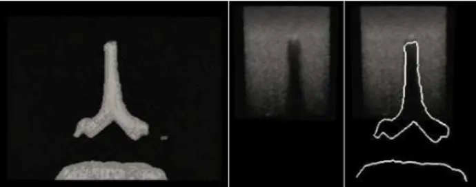
significant level of occlusion in spinal US images, it can be difficult to accurately identify the appropriate injection site. For this reason, in this paper, we consider the fusion of intraoperative US with preoperative CT as a means of guidance for spinal injections (Figure 1).
Point- and surface-based registration of US to CT data often require manual intervention and segmentation of US data, which is time consuming and susceptible to errors. To avoid these problems, we chose to focus on automated intensity-based registration methods. Among previously proposed intensity based methods for registration of US to CT data, Winter et al. [1] propose to define the bone surface in CT that is visible in an US image, with the similarity calculated as the US pixel intensities overlapping the surface. This requires a priori knowledge of the direction and orientation of the US probe. Penney et al. [2] present a method where voxel values in the US and CT data are converted to the probability of representing a bone edge. In order to have clinically relevant probabilities, a large set of prior CT and US images would have to be manually segmented.
Fig. 1. Axial slice from a CT volume of the spine phantom (left), corresponding US slice
(center) and an overlay of the CT bone contours with the corresponding US slice (right).
In Wein et al. [3,4], density information from CT data is used to iteratively simulate an US image throughout the registration process, thereby optimizing the simulation as the registration proceeds. This has the benefit of not requiring any previous knowledge of the orientation of the US probe. Although the simulation is a simplified take on the physics of ultrasound beam propagation, it is sufficient for registration purposes while remaining computationally efficient. This algorithm is extended in Shams et al. [5] to create a more realistic simulation for training physicians and technicians in the use of US imaging. The technique requires preprocessing to create a scatter volume of the CT data using the Field II simulator, which remains time consuming. In Reichi et al. [6] and Kutter et al. [7] the US simulation and registration is implemented in GPU, resulting in a dramatically decreased algorithmic run time. Gill et al. [8] propose an extension of the work from Wein et al. [3,4], a groupwise US to CT registration of vertebrae L3 to L5. The algorithm allows free motion of the vertebrae and registers all three simultaneously. The drawback of this approach is that completely free motion of vertebrae through the registration can lead to biologically unrealistic alignments.
Here we propose an algorithm that extends the groupwise registration presented in Gill et al. [8]. The algorithm allows independent motion of the vertebrae, but constrains their motion based on a well known biomechanical model. The registration is tested on a phantom printed using a surface model of a patient’s spine which
preserves a clinically realistic curvature of the spine. We present the results of the registration with various weights for the fusion of the biomechanical model with the intensity-based similarity metric.
2
Ultrasound to CT Registration
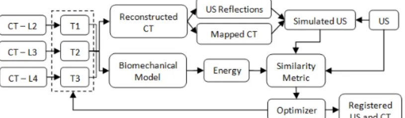
The registration workflow used in this work can be seen in Figure 2. The CT volume is initially cut into volumes, each containing a single vertebra. Voxels in the sub-volumes corresponding to bone from an external vertebra were masked. The registration treated each vertebra independently, allowing for six degrees of freedom. All vertebrae were registered simultaneously, resulting in an optimization with n×6 parameters, where n is the number of vertebrae being registered. After the transformations were applied, the sub-volumes were reconstructed into a single volume. For any overlapping voxels the maximum intensity was selected for the reconstructed volume, thus preserving bone structure. Any gaps not in the final volume were filled with a default value approximating the intensity of soft tissue in CT. The US simulation is applied to this reconstructed volume. CMA-ES is used as the optimization strategy as Gill et al. [8] found it to be robust for US to CT simulation and registration.
Fig. 2. Workflow of the biomechanically constrained groupwise US to CT registration of three
vertebrae.
There are three distinct steps in the simulation of US from CT: The Simulation of the US reflection from CT, the mapping of the CT values to those found in US, and calculations of the weights for these to images and a bias. The weights are chosen so that the simulation best represents the real US image.
The simulated ultrasound reflections model the ultrasound beam passing through the tissue as a ray. The assumption is made that the CT intensities (in Hounsfield units) can be related to the acoustic impedance values used to calculate ultrasound transmission and reflection. The simulated beam passes through each column of the volume. The transmission and reflection of the beam is calculated at each voxel based of the following equations,
∆� , , � = � ∇� , ∇� , 2� , 2 , (1) ∆� , = 1 − ∇� , 2� , 2 , (2)
� , = � , − 1 ∆� , , � , (3)
� , = �0 , , − 1 ∆� , , ∇� , < � ∇� , ≥ � , (4) where
�
is the direction of the US beam,�
is the intensity of the CT image,∆�
is reflection coefficient,�
is the simulated reflection intensity,∆�
is the transmission coefficient, is the threshold for full reflection and I is the intensity of our simulated US beam. Any gradient value greater than a set threshold (450 h.u. in our simulations) causes full reflection of the US beam intensity at that point, setting the incoming US beam intensity for all subsequent points on the scan line to zero. A log-compression is applied to the simulated reflection image to amplify small reflections, � , = log 1+�� ,log 1+� , (5)
The CT intensities are mapped to values closer to those corresponding to the tissues in the US data using an approximation of the curve presented in [3,4],
� , = 1.36� , − 1429
,
(6) The final step of the US simulation is the weighting of the simulated US reflection, the mapped CT and a bias term. A least-squares optimization is used to calculate the weights, such that the values in the simulation best match the corresponding intensities in the real US volume. The final simulation is calculated as,� , = 0 , � , + � , + , � , > 0� , = 0 , (7) where f is the simulated US image and , , are the weights for their respective images. We do not include any voxels that are occluded in the simulation as part of the weight calculation. All occluded voxels in the US simulation are set to zero. Occluded voxels are identified as any voxel where the intensity of the incoming simulated US beam is zero.
Similarity between the actual US image and simulated US image is calculated using the Linear Correlation of Linear Combination (LC2) metric presented by Wein
et al. [3,4],
2= , −� ,
2
�× �� ( ) , (8)
where N is the number of overlapping voxels between the US and CT images, and U is the actual ultrasound image intensity. All voxels, including occluded voxels, are used in the calculation of the similarity metric.
3
Biomechanical Model
Allowing free motion of vertebrae during registration is not ideal as it does not distinguish between anatomically realistic orientations of vertebrae and orientations where the vertebrae are colliding, unreasonably oriented or far apart. We propose the use of a biomechanical model of the spine to constrain the registration and to favour
anatomically acceptable alignments. The biomechanical model [9] we use models the relation between the displacement of the intervertebral structures and the reaction forces and moments:
= 100 0 50 0 −1640 0 0 110 0 150 0 580 50 0 780 0 −760 0 0 150 0 1.48�5 0 −8040 −1640 0 −760 0 1.52�5 0 0 580 0 −8040 0 1.53�5 ��� ���−1 , (9)
where K is the stiffness matrix representing the intervertebral structures. This stiffness matrix is multiplied with a vector x representing the change in translation and rotation of the intervertebral link. For our case, x is calculated as the relative transform between two consecutive vertebrae. Each vertebra is expected to have no change in rotational orientation and no translation along the x and y axes. The expected translation along the coronal axis is defined as the mean distance between the centers of consecutive vertebrae in the patient’s CT data. σote that this is meant as an approximation of the vertebral resting position.
The energy of the system based on the relative transformations between the vertebrae is calculated using the general spring equation,
=1
2( ) . (10)
The energy is calculated across all vertebrae and normalized based on the energy of a maximum misalignment (±15 mm translation along each axis and ±15° rotation about each axis),
� =
( 2, 3+ 3, 4)2× ��
,
(11)
where E is the normalized energy of the system, UL2,L3 and UL3,L4 represent the energy
of the model calculated from the relative transforms between L2-L3 and L3-L4, respectively, and Umax is the energy of the maximum misalignment.
This normalized energy is then combined with the LC2 metric to give the Biomechanically Constrained Linear Combination of Linear Correlation (BCLC2),
2= 2− �� , (12) where is a user defined weight used to blend the biomechanical model measure with the LC2 intensity based measure.
4
Results
Validation of registration accuracy was performed on a patient mimicking phantom of the lumbar spine. Vertebrae L1 to L5 were segmented from patient CT data using ITK-SNAP. The segmented data was converted to a surface model and the spine was printed using a Cimetrix 3D shape printer (Cimetrix Solutions, Oshawa, ON, Canada). In this model, the natural curvature of the spine is preserved between the patient CT and the printed spine model. The phantom was filled with an agar-gelatine recipe [10], designed to simulate the appearance of soft tissue in US. A high-resolution CT volume (0.46 mm x 0.46 mm x 0.625 mm) and an US volume were acquired from the
phantom. The US volume was reconstructed from a freehand sweep using an L14-5/38 linear-array transducer (Ultrasonix, Richmond, BC, Canada) operating at 6.6 MHz with a depth of 5.5 cm. The probe was tracked using an Optotrack Certus System (Northern Digital Inc., Waterloo, ON, Canada) and calibrated using an N-wire US phantom[11]. All registrations were performed on a Dell Precision 690, with 2×2.33 GHz Intel Xeon Quad-core CPU and 16GB of RAM.
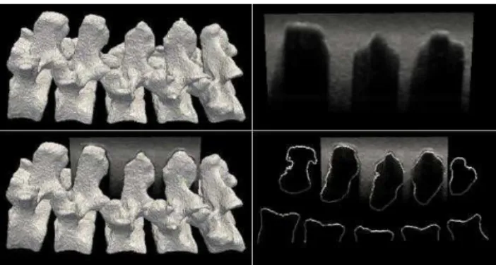
The phantom CT and US data were aligned to the gold standard, determined by fiducial markers placed on the exterior of the phantom box. The registration was performed on vertebrae L2-L4 and the US volume was cropped to correspond, as seen in Figure 3. The middle vertebrae were chosen for the registration as they contained overlap from other vertebrae at the facet joints.
Fig. 3. Surface model of vertebrae L1 to L5 (top left) and a sagittal US slice from L2 to L4 (top
right). The US is overlaid with the surface model (bottom left) and the corresponding extracted slice (bottom right).
One hundred registrations of the CT and US data were performed on the phantom with initial misalignment ranging from 0 mm to 20mm Target Registration Error (TRE). The CT volume was misaligned by a random transform chosen from a uniform distribution of ±10 mm translation along each axis and ±10° rotation about each axis. Each vertebra was then further misaligned by individually applying a random transform using a uniform distribution of ±5 mm translation along each axis and ±5° rotation about each axis. While this misalignment is larger than what would be seen in a realistic situation, we chose this distribution to ensure that the registration capture range will be greater than that of a clinical setting. The registrations were repeated for
σ
values of 0, 0.5, 1 and 2, representing the weight of the biomechanical model relative to the LC2 similarity metric.The accuracy of the registration was determined by the ability of the registration to recover to the fiducial-based gold standard and is reported as the mean TRE calculated from the misalignment of the eight corners of the volume bounding box. Results for the registration tests are presented in Table 1 and an example of the initial misalignment and the final registration is displayed in Figure 4. TRE is calculated for each vertebra and the overall error is calculated as the mean error across the entire volume. A registration is considered failed if any of the 3 vertebrae have a final TRE greater than 3mm.
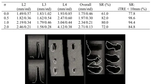
Table 1. Final TRE for vertebrae L2-L4 and the mean error of the volume are presented for all
successful registrations. Success rate (SR) is defined as the percentage of registrations where the overall final TRE is less than 3mm. SR is presented for all registration and for registrations
with initial TRE of less than 10mm. L2 (mm/std) L3 (mm/std) L4 (mm/std) Overall (mm/std) SR (%) SR: iTRE < 10mm (%) 0.0 1.49/0.57 1.83/1.02 1.93/0.85 1.75/0.46 61.0 77.8 0.5 1.82/0.36 1.62/0.54 2.47/0.60 1.97/0.30 82.0 98.6 1.0 2.19/0.34 1.79/0.46 3.04/0.44 2.34/0.21 80.0 94.4 2.0 2.46/0.21 1.58/0.28 4.12/0.38 2.71/0.13 72.0 84.8
Fig. 4. Transverse (Left), Coronal (Center) and Sagittal (Right) slices of the original US
volume overlaid with the bone contours in the misaligned CT volumes and in the registered CT volumes. The transverse slice is taken from the center vertebra L2 (Top).
5
Discussion and Conclusion
In this work we presented an US to CT registration technique for the lumbar spine that successfully registered 98.6% of volumes with initial misalignments of up to 10mm. The registration algorithm applied iterative US simulation from CT images while allowing independent motion of each vertebra. A biomechanical model was introduced to represent the intervertebral link and the system energy was calculated based on the relative transforms between the vertebrae. Integration of a biomechanical model to constrain the registration greatly improved the consistency of the algorithm. When the biomechanical model was combined with the LC2 metric with a weight of 0.5, the algorithm produced the best results; an overall accuracy of 1.97 mm, a failure rate across all registrations of 18% and a failure rate, for registration with initial misalignment less than 10 mm, of 1.4%. The registration technique was tested on patient mimicking phantom that were faithful in representing a realistic curvature of the spine (L1-L5). Furthermore, to maintain a realistic US image that included occlusion from external vertebrae, only vertebrae L2 to L4 were used in the registration. One hundred tests were performed where each vertebrae was misaligned between 0 mm and 20 mm. The tests were repeated for various weights for integrating the biomechanical model. Using a value of 0.5, 82% of all registrations were successful, while 98.6% of tests with initial misalignment of less than 10mm
were successfully registered. Increasing the weight of the biomechanical model, to
equal to1 or higher, increased the failure rate of the registration. Similarly we observe that while the inclusion of a biomechanical model improves the success rate of a registration, it can also decrease the accuracy of those successful registrations. This can be explained by the fact that the model used is an approximation and not specific to the given patient. The TRE values presented are calculated based on the misalignment of the bounding box corners for each sub-volume. We believe this is an estimate of the worst case for the error and that the error found at the facet joints (approximately centre of the box), our anatomical target, will be lower.
The mean run time of our registrations was 57.4min. To reduce this to a more clinically acceptable run time, we have begun the implementation of this algorithm in GPU. Our preliminary implementation, running in CUDA 1.1 on an Nvidia GTX285 graphics processor, reduced the registration runtime to 537s, a 6.4x improvement.
In our future work we plan to optimize the GPU implementation and extend the registration to the full lumbar spine, L1-L5. In addition, we also plan to test the registration on real patient data.
References
1. Winter, S., Brendel, B., Schmieder, K. and Igel, C.., “Registration of CT and Intraoperative 3-D Ultrasound Images of the Spine Using Evolutionary and Gradient-Based Methods”, Evol. Comput. 12(3), 284-296, (2008)
2. Penney, G.P., Barratt, D.C., Chan, C.S.K., Slomczykowski, M., Carter, T.J., Edwards, P.J. and Hawkes, D.J., "Cadaver validation of intensity-based ultrasound to CT registration," Medical Image Analysis, 10, 385-395, (2006)
3. Wein, W., Khamene, A., Clevert, D., Kutter, O., and Navab, N., "Simulation and fully automatic multimodal registration of medical ultrasound," Proc. MICCAI 4791, 136–143, (2007)
4. Wein, W., Brunke, S., Khamene, A., Callstrom, M. and Navab, N., “Automatic CT-ultrasound registration for diagnostic imaging and image-guided intervention,” Medical Image Analysis 12, 577-585, (2008)
5. Shams, R., Hartley, R. and Navab, N., “Real-time Simulation of Medical Ultrasound from CT Images,” Proc. MICCAI 5242, 734–741, (2008)
6. Reichi, T., Passenger, J., Tamayo, O. and Salvado, O., "Ultrasound goes GP: real-time simulation using CUDA," Proc. SPIE, 7261, 7261-41, (2009)
7. Kutter, τ., Karamalis, A., Wein, W. and σavab, σ., “A GPU-based framework for simulation of medical ultrasound,” Proc. SPIE, 7261, 7261-42, (2009)
8. Gill, S., Mousavi, P., Fichtinger, G., Pichora, D. and Abolmaesumi, P., “Group-wise registration of ultrasound to CT images of human vertebrae,” Proc. SPIE, 7261, 7261-59, (2009)
9. Desroches, G., Aubin, C.-E., Sucato, D. and Rivard, C.H., “Simulation of an anterior spine instrumentation in adolescent idiopathic scoliosis using a flexible multi-body model,” Med Bio Eng Comput, 45, 759–768, (2007)
10. Madsen, E., Hobson, M., Shi, H., Varghese, T. and Frank, G., “Tissue-mimicking agar/gelatin materials for use in heterogeneous elastography phantoms,” Phys. Med. Biol., 50, 5597–5618, (2005)
11. Chen, T.K., Thurston, A.D., Moghari, M.H., Ellis, R.E. and Abolmaesumi, P., "A real-time ultrasound calibration system with automatic accuracy control and incorporation of ultrasound section thickness", Proc. SPIE 6918, 69182A, (2008)