Declarative specifications
NORBERT E. FUCHS1 AND DAVID ROBERTSON2
'Department of Computer Science, University of Zurich, Zurich, Switzerland. Email: [email protected]
2
Department of Artificial Intelligence, University of Edinburgh, Edinburgh, Scotland. Email: [email protected]
Abstract
Deriving formal specifications from informal requirements is extremely difficult since one has to overcome the conceptual gap between an application domain and the domain of formal specifica-tion methods. To reduce this gap we introduce applicaspecifica-tion-specific specificaspecifica-tion languages, i.e., graphical and textual notations that can be unambiguously mapped to formal specifications in a logic language. We describe a number of realised approaches based on this idea, and evaluate them with respect to their domain specificity vs. generality.
1 Introduction
One of the advantages of computational logic is that it can serve the dual role of a high level specification language and of a programming language (Kowalski, 1985). This raises the possibility that it may be used as a medium for developing programs from preliminary specifications by refining or transforming them. For specifications one would appeal to the declarative interpretation of computational logic based on model theory, while for programs one would rely on a procedural interpretation of computational logic, e.g. SLD resolution (Lloyd, 1987).
The path from specifications to programs is fraught with difficulty because it relies not only on adequate representational capabilities at each stage, but also on appropriate forms of communica-tion with users who typically are not well acquainted with formal specificacommunica-tions. We highlight some of the key problems in supporting this process, and later demonstrate through examples how these may be addressed. Because of their importance for the software development process, we will focus on logic specifications, and mention programs derived from them only in passing.
One of the largest problems in deriving specifications is the conceptual gap between an application domain and the domain of specification methods, in particular formal ones. This gap has two closely related aspects. First, each application domain has a well-established set of concepts and notations, an accepted set of practices, and standard methods of problem solving, all of which are not easily mapped to, or reconciled with, the concepts of logic specifications. Second, application specialists identify with their conceptual world, and may resist abandoning it; they may even actively oppose the introduction of new specification methods. This is especially true for formal methods that are not easily accepted by people who use informal, or semiformal, notations like natural language, or one of the standard graphical representations for specifications.
A further problem in mapping application concepts to logic specifications is premature design. For simple relations, e.g.
Mary is the mother of John
the related declarative specification in computational logic is simply a syntactic variant involving almost no design decisions
m o t h e r ( m a r y , John)
M is the largest integer of a non-empty set of integers
we have already to design a data-structure for the set of integers, and a recursive algorithm to find the largest element
largest([I], I ) . largest([I|Is], I)
:-largestds, Mis), I >= Mis.
largest( [I|Is] , Mis) :-largestds, Mis), I < Mis.
Many more and potentially more consequential design decisions have to be made to develop declarative specifications for realistic problems taken from application domains. Making these decisions is, however, something one rather would want to avoid at this early stage of software development in order not to constrain unnecessarily the designer of the software.
Thus the transition from a problem in an application domain to a logic specification of this problem is rather thorny, since we have to
• overcome the unfamiliarity of users with formal specification methods, or even their opposition to these methods
• manage the transition from concepts of the application domain to concepts of computational logic
• make formal specifications accessible without compromising their formality • manage the transition from high to low levels of specification
• encode standard specification practice without choking ingenuity in design
In this paper, we will present approaches intended to overcome these difficulties. In section 2 we introduce application-specific specification languages as a means to develop truly declarative specifications. Then we shall give examples of systems which have used application-specific declarative languages to support the design of specifications, and we will evaluate them with respect to their domain specificity vs. generality. We could have given more, or different, examples but each of the ones we have chosen addresses a key feature of this sort of activity. The ECO system (section 3) introduces the use of schematic specification and application-specific templates as a means of packaging standard methods and controlling the acquisition of information needed to instantiate schemata. The RA system (section 4) raises the issue of context in interpreting declarative specifications, and shows how declarative frameworks can be arranged to record some of the context in which a specification is designed. The LSS system (section 5) demonstrates the value of a uniform declarative language as a lingua franca for specifications where different representations of different parts of a problem must be combined. The Attempto system (section 6) explores the relationship between natural and formal language by using a restricted form of English which is translated to a declarative specification. The Explore system (section 7) provides a mapping from graphical descriptions of specifications to an underlying formal language, thus allowing designers to build declarative specifications by direct manipulation of graphical symbols. In section 8 we conclude, summarise our results, and briefly discuss alternative approaches.
2 Declarative approaches
A basic idea, common to most, if not all, approaches presented in the sequel is the redefinition of the word declarative as used in computational logic.
Starting with the original meaning of the word that labels a sentence as declarative if it makes "true statements about the intended domain of discourse" (Kramer & Mylopoulos, 1992), the approaches follow Sterling's suggestion of designing application-specific specification languages
that allow users to express the concepts of the application domain directly, and that still can be mapped to a logic language (Sterling, 1992). "Expressing basic concepts directly, without encoding, taking the objects of the language as abstract entities" (Borger & Rosenzweig, 1994), application-specific application-specification languages are—in the true sense of the word—declarative, and have all the advantages of declarative programming (Lloyd, 1994).
We will make this more explicit. Mapping an application-specific specification language to a logic language allows us to identify real objects of the application domain denotated by elements of the application-specific language with elements of the logic language, ultimately with elements of its Herbrand model. Thus the concept declarativity of computational logic and the informally defined concept declarativity of an application-specific specification language can be considered identical. This identification has enormous consequences. First, seemingly informal application-specific specification languages turn out to be formal. Second, we are able to cross at will the border between (apparent) informality and formality—using whatever representation is more convenient— without losing preciseness. If understanding is important we may prefer the informal side, if formal operations are at stake, e.g. inference, we switch to the formal side. Thus application-specific specification languages not only allow application specialists to formulate specifications in familiar terms, but also support formal validation and verification.
Application-specific specification languages
• reduce the conceptual gap between an application domain and the domain of formal software development methods
• should make formal methods acceptable to application specialists
• due to their dual appearance ease the transition from a problem in an application domain to a logic specification of this problem
• allow formal operations in familiar terms
In brief, they directly address the problems listed in the introduction.
We will now briefly describe and evaluate a number of systems using application-specific specification languages.
3 ECO—Specifications via application-specific templates
3.1 Overview
In some domains specifications frequently follow standard patterns, with practitioners re-using these to tackle variants of earlier problems. Where this occurs it may be possible to represent these patterns using a form of parameterisable module, which we shall call a specification schema, and to construct a formal language which is sufficient to instantiate the parameters of schemata whilst being representable in terms of the informal language of the domain. One of the earliest such systems was MECHO (Bundy et al., 1979), which used schematic descriptions of standard equations used by students in mechanics problems and parameterised these by referring to features extracted from problem descriptions of the sort found in "A-level" exam questions. In MECHO the schemata were small (each being an individual equation) but more complex problems normally require large sections of specification to be parcelled together in a schema and parameterised in more sophisticated ways. This was necessary in the ECO project (Robertson et al, 1991), where the aim was to assist ecologists (who generally lack mathematical modelling skills) to construct prototype models using a representative selection of modelling paradigms.
3.2 Specification schemata
The schemata used in the ECO project consisted of six elements: • a textual summary of the purpose of the schema
• the segment of specification which it constructs
• the conditions which must be established from a dialogue with the ecologist in order for the schema to be applicable
• the actions necessary to parameterise the schema appropriately
• and the predicates which need to be supplied in addition to those constructed by the schema in order for it to be complete
A typical schema is one to find the location of a mobile object in terms of its coordinates. This solves for the goal l o c a t i o n (A,L,T) , where A is the object, L is its location and T is a time point at which it has that location. The segment of specification provided by this schema is:
l o c a t i o n ( A , L, T) :
-not(initial_time(T)),
previous_time_point(T, Tp), location(A, Lp, T p ) ,
setof((A1,L1), (nearby(A, A l ) , coordinates(Al, L I ) , S ) , coordinate_displacement(Lp, S, L ) . location(A, L, T) :-initial_time(T), coordinates(A, L ) . nearby(Al, A2) :-coordinates(Al, L I ) , coordinates(A2, L 2 ) , direct_distance(LI, L2, D ) , D < M.
which is a recursive definition of location. An object's location at any time other than the initial time is calculated as some displacement of its location, Lp, at the previous time point, Tp, with the displacement being influenced by the set, S, of coordinates of nearby objects. An object's location at the initial time is defined directly by its coordinate position. The definition of n e a r b y is that two objects, Al and A2, are near to each other if the direct distance, D, between the coordinates is less than a given threshold, M. We have emboldened and underlined this variable to denote that it plays a special role in the specification: it must be instantiated in order to complete the specification. This is done by the action:
g e t _ m a x i m u m _ j ? r o x i m i t y _ d i s t a n c e (M)
which prompts the ecologist for the appropriate parameter value. The schema also needs to ensure that the appropriate information for coordinate positions of objects is supplied in the specification, which is achieved by a second action:
construct_coordinate_goals(Cs)
which finds all the objects mentioned in the current problem description and constructs a definition of initial coordinates for each one (prompting the ecologist for appropriate positions). The resulting set of clauses, £ s , is added to the specification. These two actions demonstrate two different forms of parameterisation of schemata: by simple instantiation of variables in clauses and by construction of additional groups of clauses. To do this, ecologists need not know the details of the specifica-tion—they need only reply to the questions posed by the schema application system during parameterisation. However, the application system needs to know which schemata to suggest to ecologists when building the specification and this is done by checking conditions associated with each schema. In our example these are:
which requires that the objects we are dealing with, A, should belong to the class of objects Sa and that Sa should have a spatial representation in terms of points. This last piece of information regarding spatial representation is unlikely to be volunteered directly by ecologists so the later incarnations of the ECO system contained a mechanism for conducting a dialogue with the user, in which key schema selection conditions were progressively elicited and refined.
3.3 Dialogue in parameterising schemata
One of the major obstacles to the sort of knowledge acquisition required in parameterising schemata like the one above is the "blank sheet of paper" syndrome, which made ecologists hesitate to volunteer information to the system unless they were given some clues to the sort of information the system required—so it was necessary for the initiative to be taken at this stage by the system. This was achieved by a combination of a template filling mechanism as a means of refining formal statements; abductive inference to suggest possible new areas of dialogue to ecologists; and deductive inference to establish "background" consequences of what had been said. These mechanisms operated over a set of clauses like the examples shown below:
Rule 1 [X in object, A in attribute_name] :
spatial_representation(X) :- varies_with(A, X, location, X ) .
Rule 2 [X in object] : spatial_representation(X):- spatial_representation_ as_points(X). Rule 3 [X in object] : spatial_representation(X):- spatial_representation_ as_zones(X).
These are of the form, [V i n S, . . . ] :C, where each V is a variable in clause C and the corresponding S restricts all instances of that variable to belong to the class named by S. Rule 1 says that if an attribute of an object varies with its location then it is spatially represented. Rules 2 and 3 say that a spatial representation as points or zones imply a spatial representation. To demonstrate how the dialogue works, we show how we might obtain the information necessary to select the example schema above.
The dialogue begins by offering the ecologist a selection of template statements, designed to be opening gambits. These are rendered into pseudo-English (not shown here), with the ecologist's only task being to restrict (if necessary) the classes to which variables refer. For example, the ecologist might select the template:
[X in object, A in attribute_name] : varies_with(A, X,
location, X ) .
and restrict the scope of X to d e e r and instantiate the attribute name to b i o m a s s . This gives the assertion that the biomass of deer varies with location:
[X i n d e e r ] : v a r i e s _ w i t h ( b i o m a s s , X, l o c a t i o n , X ) . The system can now deduce (via Rule 1) that deer are spatially represented:
[X i n d e e r ] : s p a t i a l _ r e p r e s e n t a t i o n ( X ) .
To continue the dialogue, the system can now hypothesise, by abduction on Rules 2 and 3, that the spatial representation might be in terms of points or zones. It then presents these suggestions to the ecologist, who selects points in this case. The new assertion is then:
which is the information we need to select the schema introduced above. Since we would not like both points and zones to be selected (since we have no schema to deal with that situation) the system applies integrity constraints to block this option. In our example the relevant constraint is:
[X in object] : not( spatial_representation_as_points(X), spatial_representation_as_zones(X) )
3.4 Evaluation of ECO
The ECO system targets a narrow domain so it can package much of the complexity of specification inside schemata which encapsulate some standard modelling methods. The descriptions necessary to parameterise these schemata are expressed in terms familiar to ecologists and the complexity of expressions needed purely to select schemata is relatively low—thus allowing us to deploy quite simple forms of inference during our knowledge acquisition phase. This simplicity is also constraining: it relies on there being a fixed vocabulary of ecological keywords and the pseudo-English generation mechanism is domain specific. In section 6 we give a more extensive discussion of the relationship between natural language and formal specifications.
4 RA—Specifications in context
4.1 Overview
Formality in specifications is a guarantee of precision, but precision does not guarantee that the specification is appropriate to the problem it is intended to solve. In general, no such guarantee is possible because judgements of appropriateness are made subjectively by those in the domain of
application. However, we can use the structure of declarative specifications as a means of
attachment to key points of reference for those who might wish to judge the appropriateness of
our designs. This can be helpful in areas where design is regulated by codes of practice. One such area is in the offshore oil industry, where the design of safety shutdown systems is carefully regulated. The RA system was built to assist the designers of such systems by keeping track of key connections between their designs and relevant sections of the appropriate codes of practice. A detailed description of RA appears in Hesketh et al. (1996). Its main components are:
• A graphical interface which allows a safety engineer to describe key features of the production platform on which the safety system is to be installed.
• A graphical interface with which a safety engineer may construct a safety specification using schematic components.
• A system for marking segments of the textual codes of practice and associating these with proof obligations which safety engineers might choose to discharge as a means of endorsing their design decisions.
• A system for testing which proof obligations apply to a developing specification and, for those which apply, determining whether or not they are discharged.
The use of graphical systems to provide declarative specifications is discussed in detail in Section 7 so we shall concentrate here on the relationship between codes of practice, proof obligations and system specification. We do this by means of an example.
4.2 Describing and checking proof obligations
The textual markup system allows us to associate with segments of the code of practice proof obligations like those shown below. Each of these is of the form C >- G, where each C is a set of conditions which can be confirmed or denied by examining the production platform description and G is a goal which, if all the conditions in C are confirmed, may be presented to the safety engineer as a requirement to be established from the specification or the platform description.
Obligation 1: If we have an incident control centre, A, on the platform then there should be a surface process shutdown button, B, located within A.
[area(incident_control_centre,A)]
>-initiator(sps_j?ushbutton,B) & location(B, within(A))
Obligation 2: If there is a surface process shutdown button, B, on the platform then activating B should cause the installation hazard status to become red based on B.
[initiator(sps_pushbutton, B)]
>-activated(B) ==> output(installation_hazard_status(red), [B])
Obligation 3: If there is a surface process shutdown button, B, and a small power tool socket, S, on the platform then activating B should cause S to be tripped based on B.
[ i n i t i a t o r ( s p s j p u s h b u t t o n , B ) ,
s o c k e t ( s m a l l _ p o w e r _ t o o l _ s o c k e t , S ) ] > -a c t i v -a t e d ( B ) ==> o u t p u t ( t r i p ( S ) , [B])
Suppose that the platform description contains an incident control centre labelled iccl—hence a r e a ( i n c i d e n t _ c o n t r o l _ c e n t r e ( i c c l ) ) can be established. This is sufficient to make Obligation 1 (above) applicable and the safety engineer is therefore presented with the option of satisfying its goal:
initiator(sps_pushbutton,B) & location(B, within(iccl))
This can be satisfied by placing on the platform description (using the graphics tools provided) a surface process shutdown button (which we shall call s p s b l ) located within i c c l . The system records that this obligation has been satisfied. It also checks whether new obligations have been made relevant by the extra information. In this case there is a new obligation, derived from Obligation 2, which yields the goal:
a c t i v a t e d ( s p s b l ) ==> o u t p u t ( i n s t a l l a t i o n _ h a z a r d _ s t a t u s ( r e d ) , [ s p s b l ] )
This goal can only be satisfied by the safety system design, which needs to connect the s p s b l button to the output responsible for setting the installation hazard status and describe the logic by which the signal is transferred. The details of this process are given in Robertson & Hesketh (1994) and Hesketh et al. (1996) but, essentially, the safety engineer can satisfy the goal by simulating the behaviour of the safety shutdown logic; by referring to properties associated with the schema used to construct the shutdown logic; or simply by asserting that the goal holds of the design. This leaves the burden on the designer to determine the amount of evidence to associate with his or her claim to have discharged the obligation. The system's main role is to record this evidence so that it can be reconstructed when reviewing and maintaining the specification.
As well as providing a record of key points of contact between the specification and the codes of practice, automated checking for obligations can help to prompt for missing pieces of the design. For instance, although we would expect competent safety engineers to remember Obligation 2, it is easy for even experienced engineers to miss some cases of Obligation 3 because there are a large number of small power tool sockets, and it is easy to miss one. Since the RA system generates every instance of an obligation, it ensures that each is brought to the attention of the designer and a decision recorded for it. Thus, if we added two small power tool sockets ( s i and S2) to our current design we would raise the new goals:
activated(sspbl) ==> output(trip(sl), [sspbl]) activated(sspbl) ==> output(trip(s2), [sspbl])
4.3 Evaluation of RA
This system is intended to act as a support tool for an experienced designer, so it provides little control over the design itself. Instead, its task is to sit "at the elbow" of the designer and, as unobtrusively as possible, monitor the evolving design in terms of key aspects of the codes of practice. To be unobtrusive, RA must perform its checks of proof obligations automatically (although it has an interactive explanation facility). This, in turn, means that the language used to describe the relevant aspects of the codes of practice must be sufficiently simple that automatic proof attempts are guaranteed either to succeed or fail in a (short) finite time. This is guaranteed by limiting the vocabulary and grammar of our language, for example by requiring that all descriptions of the platform features should be ground and that there are no proof obligations involving unbounded recursion. Perhaps surprisingly, this restriction was not a major problem because the purpose of proof obligations in RA is not to "prove" in some absolute sense that the specification satisfies the codes of practice (which would be an impossible task) but to provide a framework which connects the specification to those areas of the codes of practice which provide a contextual basis for interpreting it.
5 LSS—Using specifications as a lingua franca
5.1 Overview
When constructing large specifications it is often necessary for experts from different engineering or commercial backgrounds to cooperate on the design. Unfortunately, it is not always possible to devise a single means of communication which suits everyone and which is also easy for each
participant to learn. This makes it necessary to think of ways to support diverse styles of expression
without isolating each individual's contribution. One way of doing this is by building tools for specification which are tuned to the roles of each type of participant but all of which build specifications in the same declarative language. In this way, the declarative language acts as a lingua franca between participants (although it is not essential that all participants are aware that the common language exists). The LSS system was built to demonstrate this architecture.
5.2 Summary of LSS tools
It consists of the following tools which, although each looks very different in its operators, all manipulate Horn clause specifications:
• A graphical tool for describing sequential, non-deterministic processes using box and arrow diagrams. These are translated automatically into definite clause grammars, which can them-selves be translated directly to Horn clauses.
• A graphical tool for describing recursive specifications using a set-based visual metaphor drawn from the familiar Venn diagram notation. These are translated into incomplete Horn clause specifications, since the diagrammatic notation is not sufficiently expressive to show all the details of the recursive specification. However, the "holes" which are left in the specification are in a form which can be filled using the techniques editing tool (below).
• A tool which constructs Horn clause specifications by first selecting a skeletal specification containing only those arguments and subgoals responsible for the flow of control in the executable specification, and then extending this incrementally by the addition of arguments and subgoals responsible for the other parts of the functionality of the specification. This method is known as techniques editing, (cf. Sterling & Yalcinalp, "Logic Programming and Software Engineering—Implications for Software Design", The Knowledge Engineering Review 11:4,1996; this issue).
provides a graphical interface for assembling these modules into larger specifications. It also provides facilities for selectively displaying related groups of modules.
• A tool which allows argumentation networks (in a style similar to that used in Ramesh & Luqi (1993)) to be drawn as a means of recording some of the non-functional requirements behind the specification and some of the interactions between these requirements. The nodes of these diagrams can refer to predicates in the specification (supplied by other tools) and if these predicates have been constructed incrementally (as in the techniques editor) the stages in their construction can be "rewound" or "played back" in order to review their construction in the context of the argumentation network.
5.3 Evaluation ofLSS
The success of this approach relies on a clear subdivision of the tasks in a collaborative specification and commitments from the participants about what the interactions between tools will be. For example, Robertson (1996) describes the construction of a simple diagnostic specification in which the process description tool is used to describe the overall patient processing procedure; the recursion tool is used to outline the basis for diagnosing each patient; and the techniques editor is used to define the algorithm for determining the covering set of hypotheses based on the known symptoms. For this interaction to be effective there must be a partitioning of effort at the beginning of the collaboration—so that the operator of the process description tool knows to leave the definition of diagnosis to the person using the recursion tool, and the operator of the techniques editor is able to identify the component of the diagnostic specification which is his or her responsibility. In other words, the flexibility afforded by this heterogeneous toolkit must be constrained by agreements on its use, tailored to particular applications. The value of the tools is to provide anchor points for such agreements and the value of declarative specifications are as a uniform foundation for the tools.
6 Attempto—Specifications in Controlled English
6.1 Overview
Natural language has a long tradition as a specification language—though uncontrolled use of natural language leads to ambiguous, imprecise and unclear specifications. It is, however, possible to define subsets of natural language that are sufficiently expressive to serve as application-specific specification languages, and at the same time sufficiently restricted to be computer-processable (Pulman & Rayner, 1994). That is, these controlled natural languages are formal and share most of the advantages of formal specification languages—specifically precision and unambiguity—but not their disadvantages such as inscrutability and non-acceptance.
Attempto Controlled English (ACE) is a computer processable subset of English for writing requirements specifications (Fuchs & Schwitter, 1996; Schwitter & Fuchs, 1996a). A specification is an ACE text that is translated into semantically equivalent representations in logic. Since this translation is reversible, an ACE specification and the derived logic specifications are semantically equivalent representations of the same formal object. In brief, ACE specifications may seem to be informal but are formal, and even executable. Because the representations are semantically equivalent one can decide to work exclusively with the ACE representation. Thus ACE offers domain specialists an application-specific language that breaks the bottleneck between informal and formal specification methods. Furthermore, ACE does not presuppose more than elementary linguistic knowledge and the willingness to learn a small number of principles on which the language is based.
The language ACE is embedded in the specification system Attempto that accepts specification texts, analyses them syntactically, and translates them into discourse representation structures (DRSs), and optionally into Prolog. A DRS is a structured form of first-order predicate logic which contains discourse referents representing the objects of the discourse, and conditions for these
discourse referents. Each sentence is translated in the context of the preceding sentences, yielding an extension of the current DRS into which the present interpretation step is incorporated.
To inform the user about the results of the analysis, the Attempto system generates a paraphrase in ACE—displaying all substitutions and interpretations made—that explains how Attempto interpreted the input text. It is up to the user to accept the interpretation, or to rephrase the input to achieve a different interpretation.
Translated specification texts are added to a knowledge base. The user can query this knowledge base by formulating questions in ACE. Questions are translated into query DRSs which are answered by deduction. The user can also execute the knowledge base, i.e., the specification, for prototyping and validation. Executing a specification leads to a dialogue between the Attempto system and the user who has to provide situation-specific information, again using ACE.
Attempto Controlled English (ACE)
The basic construct of an ACE specification is the declarative sentence. Declarative sentences can be combined by constructors to powerful composite sentences, while restricted forms of anaphora and ellipsis leave the language concise and natural.
Specification texts consist of
• declarative sentences subject + finite verb (+ complement or object)
• composite sentences built from simpler sentences with the help of constructors that mark coordination {and, or, either-or), subordination {if-then, who/which/that), and negation {not). Sentences can contain
• subject and object modifying relative sentences • anaphoric references, e.g., personal pronouns
• coordination between equal constituents, e.g. and, or • ellipsis as reduction of coordination
• negated noun phrases, no X • synonyms and abbreviations.
Furthermore, we place interrogative sentences at the user's disposal for verifying the translated specification text. Interrogative sentences comprise
• yes/no questions
• wA-questions, e.g. who, which, how
Here is a small excerpt of the ACE specification of a simple automated teller machine called SimpleMat:
The customer enters a card and a numeric personal code. If it is not valid then SM rejects the card.
The example specification text employs
• composite sentences built from declarative sentences with the help of the constructors and, if-then and not
• ellipsis, viz. The customer enters a card and [the customer enters] a numeric personal code. • compound nouns, e.g., personal code
• anaphoric references via the pronoun it and the definite noun phrase the card • abbreviations {SM standing for the name SimpleMat).
To make ACE easily learned and remembered, it is based on a small number of syntactic and semantic principles, and uses a small number of simple rules to handle ambiguity (Schwitter & Fuchs, 1996b).
Controlled English Discourse Representation Structure
The customer enters a card and a numeric personal code. I£ it is not valid
r.hen SM rejects the card.
Who enters a card? Answer:
[A customer] enters a card.
user: John is a customer, user: Bank card is a card. event: John enters the bank card.
Translation Query Execution [A.B.CD.E.F.G.H.I.J.K.L] customer(A) card IB)
event (Center (A, B)) cul(CO) numeric(E) personal code(E) event(F,enter(A,E)) cul(F.G) named (H, simplemat) IF: NOT: [I.J1 stated, valid(E)) holds!I,J) THEN: [K,L| event(K, reject(H,B)) c u K K . D Figure 1
6.3 Using the Attempto system
The Attempto system accepts specifications in ACE and translates them paragraph by paragraph into Discourse Representation Structures. In a further step, the specification can be translated into Prolog. Translated specifications can be queried in ACE, and can be executed for prototyping and validation.
Figure 1 shows the translation of the above example specification and the generated discourse representation structure which consists of a list of referents [A, B, C,...]—standing for the objects of discourse—and conditions for these referents. The figure also shows the sample query Who enters a card? and the generated answer [A customer] enters a card.
Finally, figure 1 gives an excerpt of the execution trace of the example specification. The situation-specific information (John, bank card etc.) is provided by the user while the actions associated with events are built into the execution environment.
6.4 Evaluating Attempto
Attempto Controlled English (ACE) fulfils the criteria for an application-specific specification language—at least the technical ones—since it allows application specialists
• to develop logic specifications by formulating them in ACE, using their concepts of the application domain
• to validate logic specifications by querying and executing them in ACE.
Thus logic specifications are made available to application specialists in the disguise of the familiar natural language. It remains to be seen whether this disguise will also help to eliminate the acceptance problem of formal methods.
7 Explore—Graphical specifications
7.1 Overview
Explore is an approach for the schema-based graphical and textual composition of logic specifica-tions (Fromherz, 1993; Fuchs & Fromherz, 1994). Explore has three main features:
• an object-oriented logic specification language Explore/L
• graphical views of logic specifications that can serve as application-specific specification languages
• an object-oriented framework that provides predefined schemata for partial specifications Explore provides graphical views as semantically equivalent representations of a logic specification in Explore/L, or—as will be seen shortly—parts of it. For each view there is a view editor that allows users to graphically compose specifications from predefined classes of the object-oriented frame-work, or to view an already existing logic specification in Explore/L in one of its graphic representations. Among the view editors are:
• the process editor to specify behaviour, concretely to define the overall structure of a specification as a finite state automaton
• the dialogue editor to specify window-oriented user interfaces.
Each graphical editor notation is a language for combining objects in an abstract, problem-oriented manner. Because there is a bi-directional mapping between a graphical view and its associated logic specification, we can again consider the views as application-specific specification languages.
The object-oriented framework of Explore is a set of interconnected objects that provide the basic functionality of applications in a specific domain. With such a framework available, an application is built by reusing the structure of the framework while specialising its objects to the individual requirements. In this respect, a framework is more than just an object library, as it provides not only classes and instances, but also the design of an application.
7.2 An example specification with Explore
To demonstrate working with Explore, we will sketch the development of a logic specification for an automated teller machine called SimpleMat. As its name indicates, SimpleMat provides the minimal functionality of an ATM—identifying customers, and withdrawing money with or without receipt.
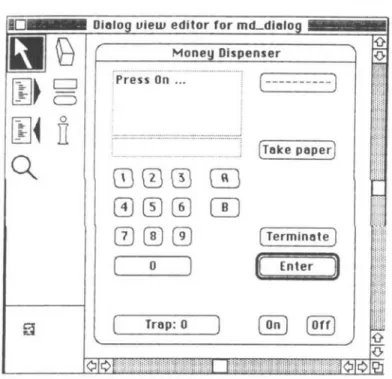
The development of the SimpleMat program consists of three steps. In the first step we define SimpleMat as a finite-state machine with the help of the tools of the process editor of Explore. Figure 2 shows the process editor and a partial view of SimpleMat's state transition network.
Process view editor for md_mochine
Dialog uieu> editor for md-dialog C D o
n
S
Money Dispenser iPress On ...3 © ©
m m in
(Take paper) ( Trap: 0 ) [ On ] [Off]Figure 3 Dialogue editor with a part of the user interface of SimpleMat.
Using the default functionality provided by the specification framework, this incomplete specification is already executable. We can put the finite-state machine through its paces and check if it has the required states and transitions.
For the second step, we assume that transitions of the finite-state machine are triggered by user interactions. We use the dialogue editor of Explore to define a user interface for SimpleMat. The names of events triggering the transitions are used to connect the transitions to elements of the user interface. Figure 3 shows the dialogue editor with a part of the user interface of SimpleMat.
Again, due to the default functionality of the framework, this new version of the SimpleMat program is executable. We can trigger transitions of SimpleMat's finite-state machine by simulating operations of the user.
In the third step, we incorporate the required functionality of SimpleMat by accessing the textual representation of the specification, i.e., the Explore/L code, and override or extend default methods and attributes.
Following is a section of the completed Explore/L specification for SimpleMat. These definitions represent two alternative transitions after the desired amount of money has been entered by the user. The first transition is chosen if the amount is valid for the current card. In this case, the money trap is instructed to prepare the money, a receipt is printed (if button A was pressed), and the dialogue interface is told to display an appropriate message. The second transition is chosen if the amount is not valid; again, a suitable message will be displayed.
tr_valid_amount(Event, Amount)
:-current_card <- valid_amount(Amount), money_trap <- set_amount(Amount),
machine: : current_state = st_amount_A Textldent = text_prep
Textldent = text_paper, printer <- print_receipt
dialog <- tr_next(Event, next_text(Textldent)). tr_valid_amount(Event, Amount)
:-not current_card <- valid_amount(Amount),
dialog <- tr_next(Event, next_text(text_iamount)). The SimpleMat specification being completed, we can execute it to validate its functionality with respect to given requirements, to complete and clarify vague requirements, or to experiment with the user interface. The execution can be visualised in the view of the dialogue editor.
7.3 Evaluation of Explore
Though the graphical views of Explore allow users to develop and to validate logic specifications in terms close to an application the view languages do not completely fulfil the criteria for application-specific application-specification languages. The main reason is that the mapping between a application-specification in Explore/L and it graphical views is only partial. Functionality added in third step by overriding and extending the classes and objects of the framework is simply not visible in the graphical views. This functionality will only become apparent when the specification is executed.
8 Conclusions
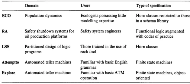
We have presented a number of approaches that should reduce the conceptual gap between an application domain and the domain of formal software development methods, should make formal methods acceptable to application specialists, and in general should ease the transition from a problem in an application domain to a logic specification of this problem. We must note, however, that all these approaches are limited—to particular problem domains, to restricted classes of users, or to a limited range of formal specifications. Table 1 summarises some of the main limitations of each system, according to these three dimensions.
Not all of the application-specific restrictions above are hard-wired into each system. For example, the ECO system library of schemata (which constrain the range of specifications which it can build) could be replaced by a different collection of schemata for an appropriate new application; the lexicon which limits Attempto to the ATM domain could be replaced by a new lexicon for a different domain. In this sense, the systems described have an element of configur-ability, provided that the new target domain is of a similar nature to the one in which the tool was
Table 1 Limitations of each system
Domain Users Type of specification
ECO Population dynamics
RA Safety shutdown systems for oil production platforms LSS Partitioned design of logic
programs
Attemptto Automated teller machines Explore Automated teller machines
Ecologists possessing little modelling expertise Safety system engineers
Those trained in the use of each tool
Familiar with basic English grammar
Familiar with basic ATM operation
Horn clauses restricted to those in a schema library
Functional logic augmented with codes of practice Horn clauses
Finite state machines Finite state machines, object-oriented
developed. Such reconfiguration is itself a specialist engineering job which requires familiarity with the principles of the original systems.
Is it possible to construct systems which are less limited but equally accessible? There are several alternative routes to this goal. The most obvious approach is to devise a single method which is both flexible and accessible but this route seems impassable, unless we reconcile the users of such a method to extensive training in a generic specification environment (which contravenes the accessibility requirement). A second approach is to combine application-specific methods which complement each other. For example, combining Attempto Controlled English with graphical and algorithmic specification languages might result in a powerful specification system that is more than the sum of each individual approach, because of the opportunities for interplay between graphics and natural language. A third option, which is part of the motivation for LSS, is to retain the use of independent tools and to use these as the basis for a large-scale plan of construction, which selects particular systems for targeted portions of the specification and forges agreements between designers for how specifications produced by each tool will be combined. This option requires a high degree of social organisation, which may only be possible in well explored domains.
References
Borger, E and Rosenzweig, D, 1994. "A mathematical definition of full Prolog" Science of Computer Programming.
Bundy, A, Byrd, L, Luger, G, Mellish, C and Milne, R, 1979. "Solving mechanics problems using meta-level inference" In BG Buchanan (ed), Proceedings of the International Joint Conference on Artificial Intelligence (IJCAI).
Fromherz, MPJ, 1993. "A methodology for executable specifications-combining logic programming, object-orientation and multiple views" PhD thesis, Department of Computer Science, University of Zurich, Switzerland.
Fuchs, NE and Fromherz, MPJ, 1994. "Transformational development of logic programs from executable specifications-schema-based visual and textual composition of logic programs" In C Beckstein and U Geske (eds), Entwicklung, Test und Wartung deklarativer Kl-Programme GMD Studien Nr. 238, Gesellschaft fur Informatik und Datenverarbeitung, pp 13-28.
Fuchs, NE and Schwitter, R, 1996. "Attempto Controlled English (ACE)" CLAW 96, First International Workshop on Controlled Language Applications University of Leuven, Belgium, March.
Hesketh, J, Robertson, D, Fuchs, N and Bundy, A, 1996. "Automating reasoning support for design" Research paper, Department of Artificial Intelligence, University of Edinburgh, Scotland.
Kowalski, RA, 1985. The Relation Between Logic Programming and Logic Specification Prentice-Hall. Lloyd, JW, 1987. Foundations of Logic Programming Springer-Verlag.
Kramer, B and Mylopoulos, J, 1992. "Knowledge representation" In SC Shapiro (ed) Encyclopedia of Artificial Intelligence Wiley.
Lloyd, J, 1994. "Practical advantages of declarative programming" Invited lecture, GULP-PRODE '94, Peniscola, Spain.
Pulman, S and Rayner, M, 1994. "Computer Processable Controlled Language" SRI International Cambridge Computer Science Research Centre, Cambridge.
Luqi, BR, 1993. "Process knowledge based rapid prototyping for requirements engineering" Proceedings IEEE Symposium on Requirements Engineering San Diego, CA.
Robertson, D, Bundy, A, Muetzelfeldt, R, Haggith, M and Uschold, M, 1991. Eco-Logic: Logic-Based Approaches to Ecological Modelling MIT Press (Logic Programming Series).
Robertson, D, 1996. "Distributed specification" Proceedings 12th European Conference on Artificial Intelligence (ECAI-96) Budapest, Hungary.
Robertson, D and Hesketh, J, 1994. "Making specification design more accountable" Proceedings ONRj ARPA/AFOSR/ARO/NSF Workshop on Increasing the Practical Impact of Formal Methods Monterey, CA. Schwitter, R and Fuchs, NE, 1996. "Attempto—from specifications in controlled natural language towards
executable specifications" GIEMISA Workshop Natiirlichsprachlicher Entwurf von Informationssystemen, Tutzing.
Schwitter, R and Fuchs, NE, 1996. "Attempto Controlled English (ACE)—a seemingly informal bridgehead in formal territory" Extended abstract. In NE Fuchs and U Geske (eds) Proceedings Poster Session, JICSLP '96, Joint International Conference and Symposium on Logic Programming Bad Honnef, Germany. Sterling, L, 1992. "A role for Prolog in software engineering" Computer Science Colloquium Department of
![Figure 1 shows the translation of the above example specification and the generated discourse representation structure which consists of a list of referents [A, B, C,...]—standing for the objects of discourse—and conditions for these referents](https://thumb-eu.123doks.com/thumbv2/123doknet/14903885.655021/11.839.163.673.107.463/translation-specification-generated-discourse-representation-structure-referents-conditions.webp)