Robolica (1996) volume 14, pp 199-203. © 1996 Cambridge University Press
A 4-degrees-of-freedom microrobot with nanometer resolution
J.-M. Breguet and Ph. Renaud
Institut de microtechnique (IMT), Swiss Federal Institute of Technology (EPFL), CH-1015 Lausanne (Switzerland) (Received in Final Form: March 6, 1995)
SUMMARY
A new type of microrobot is described. Its simple and compact design is believed to be of promise in the microrobotics field. Stepping motion allows speeds up to 4mm/s. Resolution smaller than 10 nm is achievable. Experiments in an open-loop motion demonstrated a repeatability better than 50 /xm on a 10 mm displacement at an average speed of 0.25 mm/s. A position feedback based on a microvision system will be developed in order to achieve a submicron absolute position accuracy. KEYWORDS: Microrobot; Nanometer resolution; Compact design.
I. INTRODUCTION
The assembly of microcomponents, such as micro-systems, micromachines and integrated optics, require new dedicated micromanipulators. They must have submicron resolution and/or precision, be reliable and compact, and to be made as cheaply as possible. Moreover, they must be modular and flexible in order to accommodate many different micro-assembly tasks.
All these requirements are difficult to meet with classical design and electromagnetic actuators.
Shigeru Futami et al.1 claim a 1 nm resolution with a one-axis stage mechanism, driven by an AC linear motor and guided by a rolling ball guide. Hiroshi Goto2 proposed a x-y stage capable of submicrometer positioning. A fine x-y stage (10 nm resolution, 10/xm stroke), driven by piezoelectric actuators is mounted on a "coarse" x-y stage actuated by linear DC motors. Both systems give interesting results, but they are rather bulky and their complexity increases dramatically with the number of degrees of freedom.
Solutions using flexure stages34 are confronted with the problem of limited strokes and the difficulties to add degrees of freedom.
K. Bescoke proposed a very interesting x-y (z) stage5 using inertial type, actuators. Since then, many different versions of such devices have been intensively used in scanning tunnelling or force microscopes6 (STM and AFM, respectively).
In this paper we will describe a prototype of a mobile microrobot based on inertial motion, especially designed for micro-assembly purposes.
II. DESCRIPTION
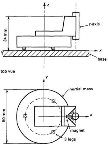
An inertial mass (<f> = 50 mm, weight = 0.155 kg) made of steel is supported by three legs (Figure 1). Each leg
consists of two piezoelectric elements (1*3*3 mm) and a glass half sphere (0 = 2 mm). The piezoelectric elements are working in a shearing mode. A 400 nm deformation is obtained with an applied voltage of 300 V. The polarisation's directions are orthogonal. X or y deformation of the feet is thus possible by exciting the upper or lower piezoelectric, respectively. The micro-robot moves on a polished steel plate (base).
A vertical axis is fixed on the platform. A "V" shaped part supports 4 piezoelectric elements. Their polarisation is oriented in the z -direction. Thanks to a magnet, a polished steel shaft (<f> = 6 mm) is maintained in a stable position against the 4 piezoelectric elements.
Two modes of operation are defined, viz. stepping and scanning modes.
In the following paragraphs, the operation of the system is described for a one-axis movement (x or _y-axis).
1 Stepping mode
A sawtooth voltage is applied to the piezoelectric (Figure 2). In the ideal case the piezo's deformation follows exactly the electrical signal. Each step consists of a slow deformation of the leg followed by an abrupt jump backward. During the slow deformation the mass follows the leg because of friction (stick), whereas it cannot follow the sudden jump because of its inertia (slip).
The "stick" phase is possible only in the case the force F is smaller than the maximum friction force Fmax:
F = m*a<Fmax (1)
When the mass alone contributes to the friction force we can write:
a<n*g (2) A sawtooth signal is characterised by a sudden acceleration (in theory, infinite). Therefore the "stick" phase exists only when the speed of the mass is synchronised with the speed of the leg. Otherwise, the leg slips either backward or forward, accelerating or decelerating the mass, respectively.
Actually, any triangle signals would allow motion. During a period of time the mass is accelerated and then decelerated (the friction force is either positive or negative). According to the duty cycle (Dc), the resulting acceleration will be either positive (Dc. > 50%), null (Dt. = 50%) or negative (£>,<50%). Beside the" ampli-tude and the frequency, speed is thus also controllable with the duty cycle of the signal.
/-axis
*- x
base
Fig. 1. The 4 degrees of freedom microrobot: x, y, z, 6z.,
Such excitation generates a speed ripple the amplitude of which depends on the signal's frequency and on the system's inertia. Moreover, a speed instability might be generated if the system is excited near its resonant frequency or higher harmonics.
For these reasons we decided to excite the system with a sawtooth signal as perfect as possible.
displacement applied voltage
A
start stick, V
slip-.A
V
stick 2 Scanning modeIn this case, a DC signal is applied to the actuators. Relation (1) must be respected in order to prevent the leg from slipping on the base. In this mode very high resolutions are possible (a few nanometers).
The stepping mode allows fast motion (up to 4 mm/s) and virtually unlimited strokes, while the scanning mode is used for fine positioning on a limited stroke (resolution better than 10 nm for a maximum displacement of 400 nm).
The combination of excitation on the three legs allows any translations on the x-y plan, rotation around z-axis, 0z, or translations and rotations combinations (this will be described in detail in a future publication).
The operation principle of the z-axis is the same. In this case the inertial mass is the shaft (ms) and the 4 legs are fixed on the microrobot. The 4 piezos are excited with a unique sawtooth signal. The force due to the magnet Fm must be strong enough to avoid the shaft to slip downward:
Fm>- (3)
III. MODELLING
Our microrobot has been modelled as a damped oscillator with a limited force (Figure 3). The model has been established for a one-degree-of-freedom movement. An inertial mass (m) is supposed to move without friction along *-axis. This mass is pulled by the leg through a spring (k) in parallel with a damper (c). A piston represents the piezo's ideal deformation. The friction force F is limited:
<F<F
m (4) xm, and xr represent the mass and the leg's absolute position, respectively. xd is the piezo's deformation corresponding to the input excitation.The dynamic equation of this system is:
m * x
m= c*(x
r-x
m-x
!t) + k* (x
r- x
m- x
d) (5)
If the leg does not slip (stick case), equation (5) becomes:m*xm + c*xm + k*xm = -c*xlt-k*xtl (6) Measurements showed that our system was
under-^ x Fig. 2. Operation principle {x or y-axis).
friction force Fig. 3. Dynamic model used for simulations
Nanometer microrobot 201 damped. If the piezo has a constant deformation rate
(x,i = - v and xd = - v * t, where v is the speed of piezo's deformation) and if the initial conditions are null, the system's response is:
(0 '*sin(wf) + v*r (7) where: 1 c k 1 c2 k • = -*— and w = A/ T * " ~ 2 = A / ~ (8) 2 m V / n 4 m 2 V m
A damped oscillation is superimposed onto a constant gradient v*t. The initial amplitude of the oscillation is proportional to the speed of the piezo's deformation.
IV. EXPERIMENTAL RESULTS
Two kinds of measurements have been conducted, micro- and macro-displacements on the x- or y-axis.
In micro-displacements, the robot position has been measured on one or a few steps using an interferometer with 5 nm resolution. A mathematical model of the microrobot's dynamic has been established according to these results.
A single step response has been measured. The step's amplitude was 400 nm and the rise time 0.5 ms. Therefore, the speed of piezo's deformation was v = 0.8 mm/s. A comparison between measurements and simulation is shown in Figure 4 and demonstrates the validity of our model.
The final microrobot step (*,„) is ca. 20% smaller than the piezo's deformation (xlt). The legs have slipped backward. Equation (7) is thus not valid any more. The measured microrobot's parameters are:
m= 0.155 kg; c = 165Ns/m; A: = 5.5106N/m; Fma, = 0.21N
The resonant frequency and friction's coefficients are: /, = 950Hz; Ms,a = 0.17; Mdyn = 0.14
We simulated the system with a MATLAB software package. The input is the piezo's excitation xcl. The mass and leg positions are xm and xr, respectively; the speed of the mass xm, as well as the limited force F, are calculated
versus time. Static and dynamic friction coefficients are considered to be equal, fi = 0.14. Figure 5 shows a simulation corresponding to the previously discussed measurements. In order to represent on the same graphics displacements velocity and force, the two previous values have been normalised to 1 and the latter to 0.5.
During the initial deformation phase of the piezo, up to a normalised time 0.2, the force attains its maximum value (Fmax = 0.21 N). The leg slips backward (xr < 0). The mass accelerates continuously, thus its speed increases linearly (x,,,). At the end of this phase, the mass moves on because of its inertia. The stocked energy in the spring is released. The leg stops, the force decreases and becomes negative down to its maximum value. The speed of the mass decreases linearly and the leg slips forward. At a c. normalised time 0.35, the leg stops again and the mass oscillates around its final position until the potential energy is dissipated.
Figures 6 and 7 show the measurements and simulation of the response of a few steps, respectively. The steps amplitude was 400 nm and the rise time 2 ms (frequency = 500 Hz). Therefore, the speed of the piezo's deformation was v = 0.2 mm/s.
In this case, the mass reaches the maximum speed corresponding to the piezo's speed deformation in one step. There is no slipping of the leg, except of course during the vertical edge of the excitation signal. The mass's speed oscillates around 0.2 mm/s. Note that for sake of clarity, the excitation signal (-*,,) has been reduced in Figures 6 and 7, and that only the first 3 steps have been simulated in Figure 7.
The microrobot's flexibility has the advantage of making slipless displacements possible, even with an easy to generate sawtooth excitation signal. Good position accuracy is thus possible, also in an open-loop operation, when the speed is low. The speed's limit depends directly on the system's stiffness (k).
On the other hand, flexibility might cause instabilities when the system is excited near its resonant frequency. Moreover, micro-assembly operations require high stiffness.
400
0.00 0.20 0.40 0.60 0.80 time {normalised to 1)
Fig. 4. Single step response, experimental and simulated. 1.00 • c -0.2 Fig. 5 0.4 0.6 0.8 time (normalised to 1)
Single step response (simulated).
4 . 0
-0.0 0.2 0.4 0.6 0.8 time (normalised to 1) Fig. 6. Ten steps response experimental.
Therefore a compromise between precision and speed has to be found. In order to satisfy the required high precision a position feedback will be necessary for automated assembly.
The following measurements apply to macro-displacements. The time required by the microrobot between two points 10 mm apart is measured. The average velocity is calculated for different excitation frequencies and amplitudes.
In the ideal case the module's velocity is given by equation (9): ' £ / * / (9) vm = xm = dl5 where: vm: module's velocity [m/s] d]5: piezo coefficient 1.33*10~9m/V
U: excitation's signal amplitude [V]
/ : excitation's signal frequency [Hz]
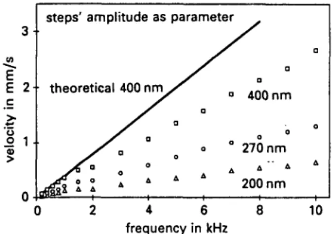
For frequencies lower than the resonant one (/r = 950Hz), the measured velocity follows nearly the
theoretical value (Figure 8). Above/,, the actual speed is considerably lower than the theoretical one. Neverthe-less, the relation is still linear. Near the resonant frequency, harmonics are excited, leading to instability. In order to achieve good speed control and with good repeatability, the fundamental excitation's frequency should not be near fr.
V) E 2\ steps' amplitude as theoretical 400 nm jf*\\ 1 I * parameter a o 0 0 A / a a a 400 nm o 0 270 nm 200 nm i i 0 2 4 6 8 10 frequency in kHz
Fig. 8. Measured velocity vs. excitation's frequency; step's amplitude as parameter.
Velocity is also controllable by means of the steps' amplitude (Figure 9). We obtained once more a good linearity. A deviation indicates that a part of the steps is absorbed in the legs and the base; the higher the frequency, the higher the absorption. In order to obtain a good controllability of the system, the steps should not be smaller than 150 nm. Otherwise irregularities on the surface's base render the movement inaccurate.
. Velocity is therefore easily controllable by means of the frequency and/or the amplitude of the excitation's signal. At low frequency and with steps larger than 150 nm a very good linearity and repeatability is obtained. At higher frequency the system's con-trollability is still good, even if the repeatability is lower.
V. CONCLUSIONS
The performance obtained with this first prototype is very encouraging. It has been demonstrated that a resolution of a few nanometers is possible in'the scanning mode. The stepping mode allows long strokes with speed up to 4mm/s. The velocity's controllability and repeatability are excellent at frequencies lower than 1 kHz; they remain satisfactory at higher frequencies. Precision will be further improved using monopolar excitation instead of bipolar excitation (as shown in Figure 2). Thanks to .Poisson's coefficient, the contact
•o c CD 09 (O a
2-i!
O ft\J \
Xr Fig. 7. 0 1 2time (arbitrary scale) First three steps response (simulated).
frequency as parameter
150 200 250 300 350
steps' amplitude in nm
Fig. 9. Measured velocity vs. steps' amplitude; frequency as parameter.
Nanometer microrobot 203 pressure between the base and the legs during its abrupt
jump backward will be reduced; the tips of the legs will move along an ellipsoide suitable for smooth motion.
However, in order to meet the high demanding requirements of micro-assembly in terms of stiffness and precision, a position feedback is necessary. The simplicity. of the system allows a very compact design, low cost prototypes and very fast development.
Our objectives are:
—submicron absolute precision (<0.1 fj.m), —nanometer resolution,
—few centimetres cubic workspace (>4 cm3), —4 to 6 degrees of freedom.
The design of the microrobot will be improved. Its stiffness can be easily increased using larger piezoelectric elements. One or two degrees of freedom will be added according to the requirement of micro-assembly applica-tions. End-effectors dedicated to micro-manipulations are already under development. Rotative actuators, based on the same motion principle, have been realized and tested successfully by the authors.
A controller based on a PC is being developed. It will allow telemanipulation as well as closed-loop operations. A microvision system will be used as position feed-back.7
VI. ACKNOWLEDGEMENTS
The authors would like to thank S. Martinelli and A. Meier who built and tested the microrobot during their student experiments. Special thanks are also due to A. Bell and A. KUng who provided the instruments for micro-displacements measurement and to the Institute's technicians for the prototype's realisation.
References
1. Shigeru Futami, "Nanometer positioning and its micro-dynamics" Nanotechnology 1, 31-37 (1990).
2. Hiroshi Goto, "XY stage capable of positioning in submicron order" J. Robotics & Mechatronics 1, 333-337 (1989).
3. Renyi Yang et al., "Design and analysis of low profile micro-positioning stage" Precision Machining: Technology
and Machine Development and Improvement ASME 1992 PED (1992) 58, pp. 131-142.
4. PI, Physik Instrument, "Products for micropositioning"
Product Line Catalog (1993).
5. K. Besocke, "An easily operable scanning tunneling microscope" Surface Science 181, 145-153 (1987).
6. L. Howald et al., "Multifunctional probe microscope for facile operation in ultrahigh vacuum" Appl. Phys. Letters 63, No. 1, 117-119(1993).
7. A. Sulzmann, "A virtual reality based interface for microtelemanipulation" ICAT'94, Proceedings (July 14-15, 1994) pp. 255-262.