HAL Id: hal-00984590
https://hal.archives-ouvertes.fr/hal-00984590
Submitted on 28 Apr 2014
HAL is a multi-disciplinary open access
archive for the deposit and dissemination of sci-entific research documents, whether they are pub-lished or not. The documents may come from teaching and research institutions in France or abroad, or from public or private research centers.
L’archive ouverte pluridisciplinaire HAL, est destinée au dépôt et à la diffusion de documents scientifiques de niveau recherche, publiés ou non, émanant des établissements d’enseignement et de recherche français ou étrangers, des laboratoires publics ou privés.
Importance of Interparticle Friction and Rotational
Diffusion to Explain Recent Experimental Results in the
Rheology of Magnetic Suspensions
Georges Bossis, Pavel Kuzhir, Modesto Lopez-Lopez, Alain Meunier, Cécilia
Magnet
To cite this version:
Georges Bossis, Pavel Kuzhir, Modesto Lopez-Lopez, Alain Meunier, Cécilia Magnet. Importance of Interparticle Friction and Rotational Diffusion to Explain Recent Experimental Results in the Rheology of Magnetic Suspensions. Magnetorheology: Advances and Applications, RSC, pp.1, 2013, 978-1-84973-667-1. �10.1039/9781849737548-00001�. �hal-00984590�
Importance of Interparticle Friction and Rotational Diffusion to Explain Recent Experimental Results in the Rheology of Magnetic Suspensions
G. Bossis1, P. Kuzhir1*, M.T. López-López2, A. Meunier1, C. Magnet1
1
CNRS UMR7336, Laboratory of Condensed Matter Physics, University of Nice – Sophia Antipolis, 28 avenue Joseph Vallot, 06108 Nice Cedex 2 France
2
Department of Applied Physics, University of Granada, Avda. Fuentenueva s/n, 18017, Granada, Spain
Table of contents
1. Introduction
2. Magnetic fiber suspensions 2.1. Microstructure
2.2. Rheology: Interparticle friction and static yield stress
2.3. Rheology: Hydrodynamic interactions and dynamic yield stress 2.4. Rheology: Non-linear viscoelastic response
3. MR fluid flows in longitudinal fields 4. Concluding remarks
1. Introduction
Magnetorheological (MR) fluids are suspensions of magnetized micron-sized particles in a dispersing liquid. When an external magnetic field is applied, the particles acquire magnetic moments, attract to each other due to dipolar forces and form anisotropic aggregates aligned preferably with the magnetic field direction. Thus, upon a field application MR fluids undergo a reversible jamming responsible for a several order of magnitude increase in effective viscosity and appearance of a yield stress – threshold mechanical stress required for onset of flow.1,2 This phenomenon, referred to as magnetorheological effect, is being effectively used in numerous smart engineering applications.3,4 Enhancement of the MR effect and/or reduction of the size of the MR devices are important problems for these applications. One of the possible solutions of such problems consists of using rod-like magnetic particles, which produce a higher MR response as compared to spherical particles.5-7 Another solution consists of changing the orientation of an external magnetic field relative to the direction of the MR fluid flow. In this chapter we aim to describe physical mechanisms of the MR effect in the suspensions of rod-like magnetic particles (called hearinafter magnetic fiber suspensions) as well as in conventional MR suspensions (composed of spherical particles) subjected to a magnetic field longitudinal to the flow direction.
New MR fluids based on magnetic micro- and nano-fibers have been developed during last few years using different techniques, such as iron electrodeposition in alumina membranes,5,8 chemical precipitation of an iron salt followed by aging in the presence of a magnetic field,9,10 reduction of cobalt and nickel ions in polyols.6,11 The magnetic fiber suspensions have shown better sedimentation stability12 and developed a yield stress much larger than the one of the suspensions of spherical particles at the same magnetic field intensities and the same particle volume fraction.7,8,10,11,13-15 Such enhanced
magnetorheological effect in fiber suspensions can be explained in terms of the interfiber solid friction16,17 and by enhanced magnetic permeability of these suspensions as compared to the permeability of conventional MR fluids.7,15 Both these effects are reviewed in details in the present publication. Note that the similar particle shape effect has been observed in electrorheological (ER) fluids18-21 and was attributed to both the physical overlapping of the elongated particles (unavoidably leading to the interparticle friction) and to their strong dielectric properties.22-24
Concerning the effect of the magnetic field orientation on the MR response of conventional MR fluids, it should be mentioned that most of the studies were focused on their flows in the presence of the magnetic field perpendicular to the flow – presumably, the case of the largest practical interest. In such geometry, the particle structures are formed perpendicularly to the flow direction, they oppose a large hydraulic resistance to the flow and generate a relatively high dynamic yield stress.12,25 In magnetic fields parallel to channel walls, the particle aggregates are expected to be oriented along the stream-lines and be (in theory) infinitely long because they are not subjected to tensile hydrodynamic forces. At such conditions, the suspension should undergo a Newtonian behavior and a certain decrease of its viscosity could be expected. This expectation is only confirmed for the suspensions composed of weakly paramagnetic particles26, such as human red blood cells, which do not belong to the class of MR fluids. However, for conventional MR fluids, composed of strongly magnetizable particles, the stress level in parallel fields is relatively high and the MR fluid develops a strong Bingham behavior,25,27 which does not corroborate with the assumption of alignment of aggregates in flow direction. Such a strong “longitudinal” MR effect has recently been explained by stochastic rotary oscillations of the aggregates caused by many-body magnetic interactions with neighboring aggregates.28 The inter-aggregate interactions are accounted for by an effective rotational diffusion process with a diffusion constant proportional to the mean
square interaction torque – a net magnetic torque exerted to a given aggregate by all the neighboring aggregates. Such a mechanism is reviewed in details in the present Chapter.
The present Chapter is organized as follows. In Sec. 2, we consider the microstructure (Sec. 2.1) and the rheology of magnetic fiber suspensions. Both effects of interparticle solid friction (Sec. 2.2) and the hydrodynamic interactions in the fiber suspension (Sec. 2.3) are thoroughly reviewed. The non-linear viscoelastic response of these suspensions developed in a large amplitude oscillatory shear (LAOS) flow is described in Sec. 2.4. Section 3 is devoted to the flow of a conventional MR fluid (composed of spherical particles) in the longitudinal magnetic field. A rotational diffusion concept is employed to explain an unexpectedly strong MR response in such geometry. Finally the conclusions and perspectives are outlined in Sec.4.
2. Magnetic fiber suspensions
In this section, we consider shear deformation and shear flow of suspensions composed of cobalt micron-sized fibers synthesized via the polyol method described in details by López-López et al.6 Anisotropic growth in the synthesis of cobalt fibers was induced by means of the application of a magnetic field during the whole synthesis time. Cobalt fibers were polydisperse with average length and width of 60 ± 24 µm and 4.8 ± 1.9 µm respectively, as shown by SEM microscopy [Fig. 2.1]. Cobalt spheres with an average diameter of 1.34 ± 0.40 µm were also synthesized in order to compare their MR response to the one of the cobalt fibers. The important feature of both types of particles is that their bulk magnetic properties are essentially the same, independently of their morphology. So, an enhanced magnetic permeability of the fiber suspensions, mentioned in Sec. 1, is explained by a weaker demagnetizing field inherent to fibers (as compared to spherical particles) due to their elongated shape. It is clear that the rheological response of the magnetic fiber suspension
depends on its microstructure developed under magnetic fields. So, the starting point of the present section will be visualization and analysis of the suspension microstructure in the absence of flows.
Fig.2.1. SEM image of the cobalt fibers (with a kind permission from the Journal of Rheology)
2.1. Microstructure
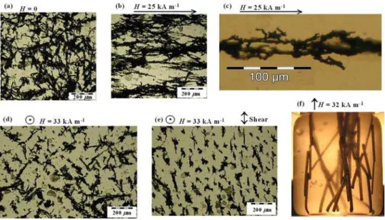
Some photos of planar structures of diluted suspensions of cobalt fibers (solid concentration 0.1 vol.%) confined between two parallel glass slides (the gap was fixed to 0.15 mm) are shown in Fig. 2.2. As is seen in Fig. 2.2(a), in the absence of magnetic field the fibers form an entangled network with approximately isotropic orientation of fibers, and even at low fiber concentration (0.1 vol.%), each fiber seems to have at least a few contact points with the neighboring ones. It can also be observed that individual fibers are gathered together in aggregates. Such aggregation in the absence of magnetic field could be due to the combination of different effects: (1) magnetic attraction between fibers because of their remnant magnetization [Mr=53 kA/m]; (2) short range van-der-Waals interaction; and (3)
mechanical cohesion between rough fiber surfaces. Such cohesion is likely due to the solid friction between fibers and could involve an important contribution to the flocculation of the fiber suspension, as reported by Mason29, Schmid et al.30 and Switzer and Klingenberg31.
Fig. 2.2. Photos of planar structures of diluted suspensions of cobalt fibers (solid concentration 0.1 vol.%) confined between two parallel glass slides (the gap was fixed to 0.15 mm). (a) in the absence of applied magnetic field; (b-c) in the presence of an applied magnetic field parallel to the glass slides; (d-e) in the presence of an applied magnetic field normal to the glass slides: unstrained suspension (d) and strained suspension (e). (f) photo of a 3D structure of a model fiber suspension under the presence of applied magnetic field (with a kind permission from the Journal of Rheology).
When a magnetic field parallel to the glass slides is applied, the fiber network becomes deformed and approximately aligned with the field direction [Fig. 2.2(b)]. Notice that the fiber network remains entangled, the fibers are linked to the neighboring ones and, therefore, there is no complete alignment with the field. This can be explained by appearance of the solid friction between fibers, which hinders their motion and does not allow them to get completely aligned with the field. Hence, the structure observed is not at equilibrium. Otherwise, without friction, the free energy of the fiber suspension would have been minimized, and a structure with all the fibers aligned completely with the magnetic field, joined end by end with the neighboring ones, would have been observed. A zoomed view of the fiber network upon magnetic field application is presented in Fig. 2.2(c). As observed, the fibers are rather polydisperse and have an irregular rough surface. They are linked to each other either by their extremities or by their lateral sides. In the latter situation, two contacting
fibers either are attached by their lateral sides or cross each other at some angle. It seems that any type of interfiber contact is equiprobable.
Alternatively, when a magnetic field normal to the glass slides is applied, the fibers tend to become aligned in the vertical plane, i.e. transversely to the glass slides [Fig. 2.2(d)]. However, as can be observed, some fiber aggregates are so big that they cannot be aligned in the vertical plane because their movement is restricted by the gap between the glass slides. And even smaller fiber aggregates do not get strictly perpendicular to the glass slides –fibers are always attached to the neighboring ones by magnetic and friction forces. Note that this structure is rather different from the column-like structure observed in suspensions of spherical magnetic particles.2 Notice also that when this fiber suspension is sheared (the upper glass slide is displaced horizontally), under the presence of vertical magnetic field, the fiber aggregates get more oriented in the direction of shear [Fig. 2.2(e)]. Thus, we believe that upon magnetic field application, the fibers gather into aggregates, which span the gap between the glass slides, and they are tilted, when sheared, in the direction of the shear.
Finally, a photo of a 3D structure of a model fiber suspension consisting of steel rods (15 mm in length and 1 mm in diameter) in silicone oil, under the presence of applied magnetic field, is shown in Fig. 2.2(f). Similarly to the planar structures discussed above, the fibers form a dendrite-like structure oriented preferably along the magnetic field lines. As seen in Fig. 2.2(f), most of the contacts between fibers are either side-by-side or side-by-end, while end-by-end are infrequent. In fact, this model structure shown in Fig. 2.2(f) is quite similar to the structure shown in Fig. 2.2(c). In both cases the fibers can either attach to neighboring ones by their lateral side (line contact) or cross each other at a certain angle (point contact).
The existence of different types of interfiber contacts is an essential point that must be taken into account to theoretically model the magnetorheology of suspensions of magnetic
fibers. This is done in Sec. 2.2, where we introduce a microstructural model for magnetic fiber suspensions and explain the enhanced MR response of these suspensions in terms of interfiber solid friction. Theoretically determined static yield stress of the fiber suspension is compared to the measured one obtained from experiments on quasi-static shear deformation of the suspension.
2.2. Rheology: Interparticle friction and static yield stress
Let us consider a suspension of identical magnetic fibers confined between two infinite plates. The distance between these plates is supposed to be much larger than the fiber length. When the magnetic field is applied normally to the plates, the fibers attract each other and form some kind of anisotropic network. Precise details of such a network may only be predicted by particle level numerical simulations. To gain the first insight into the rheology of the magnetic fiber suspension, we impose artificially a stochastic near-planar suspension structure, which seems to be rather close to the one observed in experiments [Fig. 2.2]. In more details, we suppose that all the fibers lie more or less in planes parallel to the shear plane. Thus, the fiber suspension can be represented as a series of sheets, each one parallel to the shear plane, and containing stochastically oriented fibers, as depicted in Fig. 2.3(a). The suspension is sheared by a displacement of the upper plate, and the strain angle is Θ. We shall calculate the stress-vs.-strain dependency and the suspension yield stress under the following considerations:
1. The fibers are supposed to not to slip over the plates.
2. The magnetic dipolar forces acting between fibers are negligible [according to Kuzhir et al.17] and the only forces exerted on the fibers are the contact forces.
3. Most of the contact points are located on the lateral fiber surface rather than at the fiber extremities.
4. The surface of the fibers is rough [cf. Fig. 2.1]. When the suspension is sheared, all the fibers slide over each other and exert friction forces on the neighboring fibers. In general, the value of these forces should depend on the shear rate. However, at low shear rates, considered in this section, a boundary lubrication regime between rough fiber surfaces is expected. In this regime, the friction forces appear to be independent of speed32 and are supposed to follow the Coulomb’s friction law, fτ = ξfn, with ξ – the friction coefficient and fn – normal force exerted
by a neighboring fiber to a given fiber. At higher shear rates, considered in Sec. 2.3, the surface roughness generates a lifting force leading to hydrodynamic lubrication between fibers with the friction force proportional to the shear rate.
5. The contact forces between fibers belonging to different sheets are entirely defined by interparticle magnetic forces. Since the latter are neglected, the former should also be negligible. Therefore both the normal force fn and the friction force fτ are supposed to belong
to the shear yz-plane and the friction force is assumed to be longitudinal with the fiber major axis.
Fig. 2.3 Geometry of the near-planar structure. (a) The fiber network can be “sliced” into sheets parallel to the shear yz-plane. (b) Projection of the fiber network onto the xz-plane (with a kind permission from the Journal of Rheology).
The mechanical stresses arising in strained fiber suspensions are due to contact forces acting on fibers and the latter are, to a large extent, determined by the balance of torques. The projection of torques (exerted to a given fiber) onto the shear yz-plane reads:
contacts 0
m n
T sf
− +
∑
= , (2.1)where s is the distance between the center of the given fiber and the contact point; the summation in second term of the left-hand side of Eq. (2.1) is performed over all contact points of a given fiber; Tm is the magnetic torque exerted by the external magnetic field to a
given fiber; the expression for this torque reads:17
2 2 0 1 sin 2 2 2 f m f f T µ χ V H θ χ = + (2.2)
where H is the internal magnetic field, θ – the angle between a given fiber and the magnetic field vector [Fig. 2.3(a)], Vf = 2πa2l – the volume of the fiber, a and l – the fiber radius and
semi-length respectively, χf – the fiber magnetic susceptibility, and µ0 = 4π 10-7 Henry/m –
Since there is no any significant flow in the quasi-static deformation regime, the only contribution to the suspension stress tensor is the particle stress. This is a volume average of the stresses contributed by each fiber. In our particular case, the forces acting on the fibers are concentrated in single points (point-wise interactions), and the expression for the suspension shear stress (yz-component of the stress tensor) is given by Larson33 and Toll and Manson:34
fibers contacts 1 z y r f V σ =
∑ ∑
. (2.3)Here V is the total volume of the suspension, r is the vector connecting the fiber center with the contact point, rz =scosθ is the projection of the vector r onto the z-axis,
cos sin
y n
f = f θ+ fτ θ is the projection of the contact force f onto the y-axis (flow direction); the sum is taken over all the contact points on every particle of the suspension. Taking into account Eq. (2.1) and the relation fτ = ξfn, we arrive to the following expression for the shear
stress: 2 fibers 1 1 cos sin 2 2 m m T T V σ = ⎛⎜ θ+ ξ θ⎞⎟ ⎝ ⎠
∑
(2.4)Replacing the magnetic torque Tm by the expression (2.2) and averaging the stress over
all possible fiber orientations, we get the final expression for the suspension stress:
2 2
2 2 2 2
0 0
contribution from magnetic torque contribution from friction forces induced by the magnetic torque
1 1
sin 2 cos sin 2
2 2 4 2 f f f f H χ H χ σ = Φµ χ θ θ + Φξ µ χ θ + + (2.5)
The angular mean in Eq. (2.5) is calculated via the angular distribution function F(θ) of the near-planar structure:
∫
−
= 2
2 ( )(...)
... π
strongly influenced by the shear deformation, and the angular distribution function is assumed to be Gaussian and centered at the strain angle, Θ [Fig. 2.3(a)]:
] ) ( exp[ ) (θ =α1 −α2 θ −Θ 2 F (2.6)
Hear α1 and α2 are the parameters of the distribution function. In the absence of shear
the fiber distribution is considered to be isotropic in the yz-plane. When the strain is progressively increased, the fibers incline with the strain and get more aligned. At a threshold strain angle, Θa, the structure is supposed to be completely stretched, the straight fiber chains
making the angle Θa with the magnetic field. Under these conditions, the coefficient α2 of the
distribution function must be zero at zero shear, and infinite at the strain angle Θa. A simple
function, α2(Θ) respecting the above conditions and adopted in our model is
2 /( a )
α = Θ Θ − Θ . The first coefficient, α1, is found from the normalization condition:
2 2F( )d 1 π π θ θ − =
∫
, i.e.(
)
1 2 2 1 2exp 2( ) d π πα =
∫
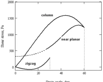
− ⎡⎣−α θ− Θ ⎤⎦ θ − . Finally, the threshold strain angle is set at Θa = 60º [cf. Kuzhir et al.17].The stress-strain curve obtained by this model is plotted in Fig. 2.4 and compared with the corresponding curves obtained for other two microstructural models – the models of the column and zigzag structures described in details in Kuzhir et al.17 As is seen in this figure, the stress-strain relation for the near-planar structure presents a local maximum, which corresponds to the yield stress. This maximum is observed at a strain angle close to the angle Θa of complete alignment of the structure. Note that the stress-strain curve departs from
non-zero shear stress at non-zero strain. This is not surprising because we have assumed that, at any strain, all fibers slide over each other and experience the friction force, fτ =ξfn. At zero strain, the normal forces between randomly oriented fibers are not zero, leading to non-zero friction forces. In reality, when the fibers do not slide, the friction forces between them can
take any value within the range: −ξfn ≤ fτ ≤ξfn. Consequently, at small strain angles our model cannot predict with confidence the shear stress of the near-planar structure. It is the reason why we have plotted the initial part of the stress-strain curve as a dashed line [Fig.2.4].
Fig. 2.4. Stress-strain curve for column, zigzag and near-planar stochastic structure of a fiber suspension at magnetic field intensity H0 = 100 kA/m, fiber volume fraction Φ = 0.05, and friction coefficient ξ = 1 (with a
kind permission from the Journal of Rheology).
Let us now compare the predictions of the theoretical models with the experimental values of the static yield stress of the fiber suspensions. Fig. 2.5 shows the magnetic field dependency of the yield stress for four solid volume fractions, Φ = 0.01, 0.03, 0.05 and 0.07. The five curves in each graph correspond to the theoretical results using both the model of the near-planar stochastic structure described in the present chapter and the models of the column or zigzag structures described in Kuzhir et al.;17 the solid circles correspond to the experimental results. As observed in Fig. 2.5, the highest estimation of the yield stress is given by the model of the column structure with friction (upper solid curve), and the lowest estimation by the model of the zigzag structure (lower solid curve). At magnetic fields
H0≥100 kA/m, the experimental points lie between these two curves. At lower magnetic fields
This is possibly due to the underestimated value of the initial magnetic susceptibility used in our calculations, χi = 17.3.
Fig.2.5. Yield stress of fiber suspensions versus external magnetic field intensity, H0, for different fiber volume
fractions, Φ: (a) Φ = 0.01; (b) Φ = 0.03; (c) Φ = 0.05; and (d) Φ = 0.07. The upper and the middle solid lines correspond to the model of the column structure with ξ = 1 and ξ = 0, respectively; lower solid line – model of the zigzag structure with ξ = 1; dashed line – model of the near-planar stochastic structure [Eq. (2.5)] with ξ = 1; solid circles: experimental data (with a kind permission from the Journal of Rheology).
Comparing different theoretical predictions, we note that the yield stress for the column structure with the friction coefficient ξ = 1, is roughly two times higher than the yield stress for the same structure without friction. By analyzing the zigzag model we can identify the two reasons why this model predicts the lowest yield stress. Firstly, the strained zigzag chains act as compressed springs that push upward the rheometer plate. Secondly, this structure has a relatively low anisotropy compared to the column structure. The most realistic model – the model of the near-planar stochastic structure gives a reasonable correspondence with the experiments at fiber volume fractions Φ = 0.05 and 0.07 [Fig. 2.5(c)-(d)]. This model
takes into account the friction between fibers as well as the progressive alignment of the fiber network with increasing strain.
Let us now analyze the effect of solid concentration on the yield stress of fiber suspensions. The three inspected models –column structure, zigzag structure and near-planar structure– give almost linear concentration dependence of the yield stress, which comes from the assumption #5 that the friction force between fibers is longitudinal and always equal to
n
f
ξ . In this case, in Eq. (2.3), the sum
∑
contacts zr fy over all the contact points on a givenfiber is simply proportional to the magnetic torque acting on a considered fiber, whatever the number of contact points is. Consequently, the theoretical yield stress is linear in the number of fibers per unit volume (i.e. in the concentration) rather than in the total number of contact points. Such a linear trend is inconsistent with a power-law concentration dependence of the yield stress observed experimentally:14 1.5
Y
τ ∝ Φ . In a real situation of a 3D stochastic structure, the friction term of the stress is not necessarily proportional to the magnetic torque and can hide a stronger concentration dependence. This is the case of isotropic suspensions of non-magnetic elastic fibers, for which the yield stress is proportional to the number of contact points per unit volume, which varies as the square of the solid volume fraction.34,35
Note finally, that experiments show that the static yield stress of the cobalt fiber suspensions is approximately three times larger than the one of the suspension of the cobalt spheres at the same volume fraction and the same magnetic field.14 The microstructural model presented in this Section reveals an importance of the interparticle friction in fiber suspensions. According to Eq. (2.5), the solid friction gives a contribution to the total stress, which is, at least, comparable with the magnetic torque contribution. So, since the interparticle friction is expected to be much weaker in a suspension of spherical particles, it is now clear that the fibers should give a stronger MR response as compared to spheres. Another
possible reason of an enhanced MR effect in fiber suspensions – a stronger magnetic permeability of the fiber suspension – is studied in the next section in conjunction with experiments and modeling of steady shear flows at shear stresses above the yield point.
2.3. Rheology: Hydrodynamic interactions and dynamic yield stress
Now, instead of a static shear deformation below the yield stress, we shall consider a steady shear flow of the fiber suspension generated by a continuous motion of the upper rheometer plate with velocity v. Consequently, the shear rate is equal to γ =v b/ , where b is the gap between the two plates. As previously, an external magnetic field H0 is applied
perpendicularly to the planes.
In order to find a rheological law of the fiber suspension under steady shear flow, we introduce the following assumptions:
1. The fibers have a cylindrical shape and are characterized by a half-length l and a radius a. In the presence of field, the fibers attract to each other and form cylindrical aggregates with half-length L and radius A. We assume that the fibers in the aggregates are all aligned parallel to each other and form therefore a closely packed bundle of cylindrical particles having a internal volume fraction of Φa=π2/12 [see Bideau et al36].
2. The aggregates are supposed to move affinely with the flow without rotation.
3. We do not take into account collisions, contact forces (compressive and friction forces) and hydrodynamic interactions between aggregates. Strictly speaking, this assumption is verified for diluted fiber suspensions with a volume fraction, Φ <( / )A L 2, however, as we shall see, it still give a reasonable agreement with experiments until the volume fraction of Φ=5% for the experimental range of aspect ratios 7<L/A<13.
4. We do take into account hydrodynamic interactions between the aggregates and the suspending liquid, which tend to align the aggregates in the flow direction by exerting a hydrodynamic torque on them. On the other hand, the external magnetic field applies a restoring torque on aggregates. So, at equilibrium, both torques are balanced and define an equilibrium angle θc of the aggregates’ orientation with respect to the magnetic field.15
5. Under shear, the aggregates are subjected to tensile hydrodynamic forces, which break them in their weakest point – their central transverse section. On the other hand, the cohesive magnetic forces between fibers consolidate the aggregates. So, the equilibrium aggregate length (or rather aspect ratio L/A) is found from the balance of these forces. Such an approach has been employed in many calculations of the rheological properties of conventional MR fluids composed of spherical particles.37-39 In our case of fiber suspensions, we use more rigourous expressions for the interparticle magnetic force [taking into account the magnetic saturation effects according to the model of Ginder et al.40] and for the hydrodynamic force and stress [using the slender body theory of Batchelor41 with appropriate corrections accounting for a finite aggregate length].
6. At low shear rates or high magnetic fields, the aggregates become very long and, therefore, they may span the gap between the two planes (rheometer gap). In this case, the orientation of the aggregates and the shear stress developed in the suspension will be different from those found for unbounded shear flow. We assume that the aggregates are extensible: when they are inclined at an angle θ relative to the magnetic field direction, they are stretched and continue to touch the walls but slide over the walls without solid friction, such that their length is L=b/ 2 cosθ . Alternatively, at high shear rates or low magnetic fields, all the aggregates are expected to be destroyed by the shear. In this case, the suspension is completely disaggregated and composed of isolated fibers whose aspect ratio, l/a, no longer depends on the shear rate. In conclusion, three distinct aggregation regimes are expected in a
shear flow of magnetic fiber suspensions depending on the ratio of hydrodynamic to magnetic forces – so-called Mason number, Mn: (1) aggregated state with confined aggregates at
Mn<Mnc; (2) aggregated state with free aggregates at Mnc<Mn<Mnd; and (3) disaggregated
state at Mn>Mnd, the expressions for critical Mason numbers Mnc and Mnd being given in
Gómez-Ramírez et al.15
To find the shear stress of the fiber suspension under steady shear flow, we use an expression similar to the one derived by Brenner42 and Pokrovskiy43 for a suspension of non-spherical force-free particles subjected to an external torque [magnetic torque Tm in our case,
cf. Eq. (2.2)]. Substituting the corresponding expressions for the aggregate orientation angle,
θc, and the aspect ratio, L/A [cf. assumptions (4), (5)], as well as using the results of the
slender body theory41 for the rheological coefficients, we arrive to the final expression for the shear stress at the three considered aggregation regimes:
2 3/ 2 0 2 2 0 0 3/ 2 1 0 2 2 3 0 /(2 cos ) 2 1 2 sin cos 3 ln /( cos ) (1 ) sin cos , 2 (1 ) c c c a a c f c c c f b A f b A H Mn Mn θ σ η γ η γ θ θ θ χ µ χ θ θ ⎡ ⎤ ⎛ Φ ⎞ Φ ⎣ ⎦ = ⎜ + ⎟+ + Φ Φ ⎡ ⎤ ⎝ ⎠ ⎣ ⎦ − Φ + Φ < + − Φ (2.7a) 1/ 2 2 2 2 1 2 2 0 0 2 2 3 (1 ) 2 ( ) 1 2 sin cos 3 2 (1 ) (1 ) sin cos , 2 (1 ) f S c c a f f c c c d f M f H H f f Mn Mn Mn χ σ η γ µ χ θ θ χ θ θ χ ⊥ ⎧⎛ − Φ ⎞ ⎛ Φ ⎞ ⎪ = ⎜ + Φ ⎟+ Φ ⎨⎜⎜ + − Φ ⎟⎟ + ⎝ ⎠ ⎪⎝⎩ ⎠ ⎫ − Φ ⎪ + ⎬ ≤ ≤ + − Φ ⎪⎭ (2.7b)
(
)
2 2 2 0 0 1 2 2 3 0 2 ( / ) 1 2 sin cos 3 ln(2 / ) (1 ) sin cos , 2 (1 ) c c f c c d f l a f l a H Mn Mn σ η γ η γ θ θ χ µ χ θ θ = + Φ + Φ + − Φ + Φ > + − Φ (2.7c)Here η0 is the viscosity of the suspending liquid; A0 is radius of the unstrained fiber
aggregates, which is found by the energy minimization; χf is the magnetic susceptibility of a
single fiber; H is the internal magnetic field; MS is the magnetization saturation of the cobalt
fibers; and f1 ,f2 ,f⊥ are numerical factors, coming from the slender body theory of
Batchelor,41 functions of L/A, taking into account the finitness of the fiber aspect ratio [the expressions for these factors can be found in Gómez-Ramírez et al.15]. All the three expressions (2.7) for the shear stress contain three terms, the first of which corresponds to the solvent contribution, the second one comes from the longitudinal hydrodynamic stress generated by the aggregates, and the last one is connected to the magnetic torque exerted on aggregates.
The theoretical [Eq. (2.7)] and experimental dependencies of the shear stress on the shear rate are shown in Fig. 2.6 for the fiber suspension containing 5 vol.% of particles.
Fig.2.6. Flow curves for a fiber suspension with Φ=0.05 in the presence of a magnetic field. Lines correspond to the theory; the symbols correspond to experimental data obtained using a controlled-stress rheometer. Full and open symbols stand respectively for increasing and decreasing shear stress. Both theoretical and experimental curves correspond to magnetic fields of intensity H0, from bottom to top: 0, 6.11, 12.2, 18.3, 24.4 and 30.6
kA/m. The inset shows the same flow curves at low shear rates (with a kind permission from the Journal of Rheology).
We see that, both in experiments and in theory, the flow curves have two straight sections with different slopes, the left one with a steep slope and the right one with a less steep slope. Let us consider each part separately.
The left part of the flow curve corresponds to the state of confined aggregates. The aspect ratio of the aggregates is very high and they span the rheometer gap. Therefore they offer a high hydraulic resistance to the flow, which could explain the steepness of this part of the curves, corresponding to a high apparent viscosity at low shear rates. The theoretical zero-shear viscosity (the initial slope of the flow curves) can be easily found from Eq. (2.7a) with an appropriate expression for the angle θc:
[
]
[
]
2 0 0 0 0 0 /(2 ) 4 ( / ) 1 2 3 ln / a b A f b A γ γ η τ γ η ⊥ → → ⎧ Φ ⎛ ⎞⎫ ⎪ ⎜ ⎟⎪ ≡ = ⎨ + ⎜ + ⎟⎬ Φ ⎪ ⎝ ⎠⎪ ⎩ ⎭ (2.8)In the limit of small shear rates, the slopes of all the theoretical curves do not depend on the magnetic field intensity but depend on the rheometer gap b. For the fiber suspension with 5% volume fraction, the zero-shear viscosity predicted by Eq. (2.8) is equal to 13η0,
which is 12 times the differential viscosity (final slope) corresponding to high shear rates. As we can see in the inset of Fig. 2.6, our theoretical model underestimates the zero-shear viscosity of the flow curve. This is probably because we have neglected hydrodynamic interactions between the aggregates and the walls. Recently, Berli and de Vicente44 have proposed a structural viscosity model, which also predicts a large but finite zero-shear viscosity of MR fluids independently of the rheometer gap. Unfortunately, we cannot compare this theory with our experiments since the former employs an unknown parameter. Therefore, the questions, whether the zero-shear viscosity depends on the rheometer gap and what mechanism governs this quantity, remain open.
The rounded part of the flow curves corresponds to the transition between the regime of confined aggregates to that of free aggregates, which happens at Mason number Mnc. Note
that the shear rate in the rheometer gap increases linearly with the radial distance from zero on the disk axis to a maximal value, γR at the disk edge. So, depending on the position in the gap, the zone of confined aggregates can coexist with the zone of free aggregates, and the transition between both regimes happens smoothly with increasing the shear rate γR, which explains the rounded shape of the transition zone.
Starting from a shear rate γ ≈50 s-1, the experimental and theoretical curves become linear and almost parallel to each other, which corresponds to the Bingham rheological law,
Y
σ σ ηγ= + , with σY being the dynamic yield stress and η the plastic viscosity. The dynamic
yield stress is defined as a linear extrapolation of the flow curve to zero shear rate. We observe a reasonable quantitative correspondence between the theoretical and the experimental flow curves at γ >50 s-1, without introducing any adjustable parameter. The Bingham behavior observed experimentally at γ >50 s-1 is well predicted by our theory. In our theory, the stress σY contains the hydrodynamic part, which is proportional to ( / )L A 2η γ0 and the magnetic part, which does not depend on γ . Due to the action of hydrodynamic tensile forces, the aggregate length appears to be proportional to γ−1/ 2, thus, the hydrodynamic part of the stress σY and, consequently, the stress σY itself do not depend on the shear rate. So, as
in MR suspensions of spherical particles,37,38 in our model, this stress is assigned to the dynamic yield stress. Notice that, in both the theoretical and the experimental flow curves, the regime of isolated fibers is not distinguished from the regime of free aggregates. This is because the considered transition happens at relatively high shear rates (Mason numbers Mnd),
Notice finally, that the experimental flow curves show only a very narrow hysteresis, which could mean that the hydrodynamic forces dominate over the forces of solid friction, at least, for semi-dilute suspensions (Φ<0.05) and at Mason numbers Mn>1. Therefore, the assumption #3 of the absence of contact and friction forces seems to be justified for a steady flow at such parameters.
The most important parameter characterizing MR response of MR fluids in steady flows is the dynamic yield stress. Its theoretical value for the fiber suspension is easily obtained from Eq. (2.7) by putting the shear rate γ = and the coefficients 0 f1 = f2 = f⊥ ≈ : 1
1/ 2 2 2 2 2 2 3 0 (1 ) (1 ) 2
sin cos sin cos
3 2 (1 ) 2 (1 ) f f S Y c c c c f f M H H χ χ σ = Φµ ⎧⎨⎪⎜⎛⎜ +χ − Φ− Φ ⎞⎟⎟ θ θ + +χ − Φ− Φ θ θ ⎪⎬⎫ ⎪⎝ ⎠ ⎪ ⎩ ⎭ (2.9)
A similar expression has also been derived for the dynamic yield stress of the conventional MR fluids composed of spherical particles.15 Let us now compare the rheology of suspensions of magnetic fibers with the rheology of suspensions of spherical particles, both made of the same material (cobalt) and at the same volume fraction 5 vol.%. The dependencies of the apparent dynamic yield stress on the magnetic field intensity are shown in Fig.2.7 for both suspensions. Both experiments and theory show that the dynamic yield stress of the suspension of fibers is a few times higher than that of the suspension of spheres. Note that the magnetization of both spherical and fiber-like cobalt particles is similar, and both types of particles are micron-sized, so non-Brownian. Thus, the difference in the yield stress cannot be explained by different magnetic properties, neither by their Brownian motion, but rather comes from a shape-dependent demagnetizing field inside the particles. In more details, the magnetization Ma of a particle aggregate varies linearly with the magnetization Mp
of a separate particle, and the latter is proportional to the magnetic field intensity Hp inside the
the particle shape, the magnetic field Hp appears to be lower inside the spherical particles than
inside the fiber-like particles, so the magnetization and the magnetic susceptibility of the aggregates composed of spherical particles is a few times lower than those of the aggregates of fibers. Since the yield stress is a growing function of the aggregate magnetic susceptibility, it appears to be larger for the fiber suspension.
Fig.2.7. Dynamic yield stress for suspensions of cobalt particles as a function of the intensity of the external magnetic field, H0. The volume fraction Φ=5% in both cases. Circles – experiments for the suspension of cobalt
fibers; squares – experiments for the suspension of spherical particles; 1 – theory for the fiber suspension; 2 – theory for the suspension of spherical particles (with a kind permission from the Journal of Rheology).
Inspecting Fig. 2.7, one can see that our theory predicts the dynamic yield stress for fiber suspension reasonably well, but it underestimates the dynamic yield stress for suspensions of spherical particles. This could be due to the underestimation of the magnetic susceptibility of the aggregates of spherical particles, as was shown by comparing the permeability of an elastomer containing chain like structures of magnetic particles to that of one having an isotropic distribution of particles.45
In addition to steady shear flows of MR fluids, oscillatory shear flows are even more frequently employed in MR devices, such as MR dampers and shock absorbers. The strain amplitude of such flows in real devices often overcomes by orders of magnitude the limit of the linear viscoelastic regime. Therefore a large amplitude oscillatory shear (LAOS) response
of magnetic fiber suspensions is of high practical interest and is considered in the next Section2.4.
2.4. Rheology: Non-linear viscoelastic response
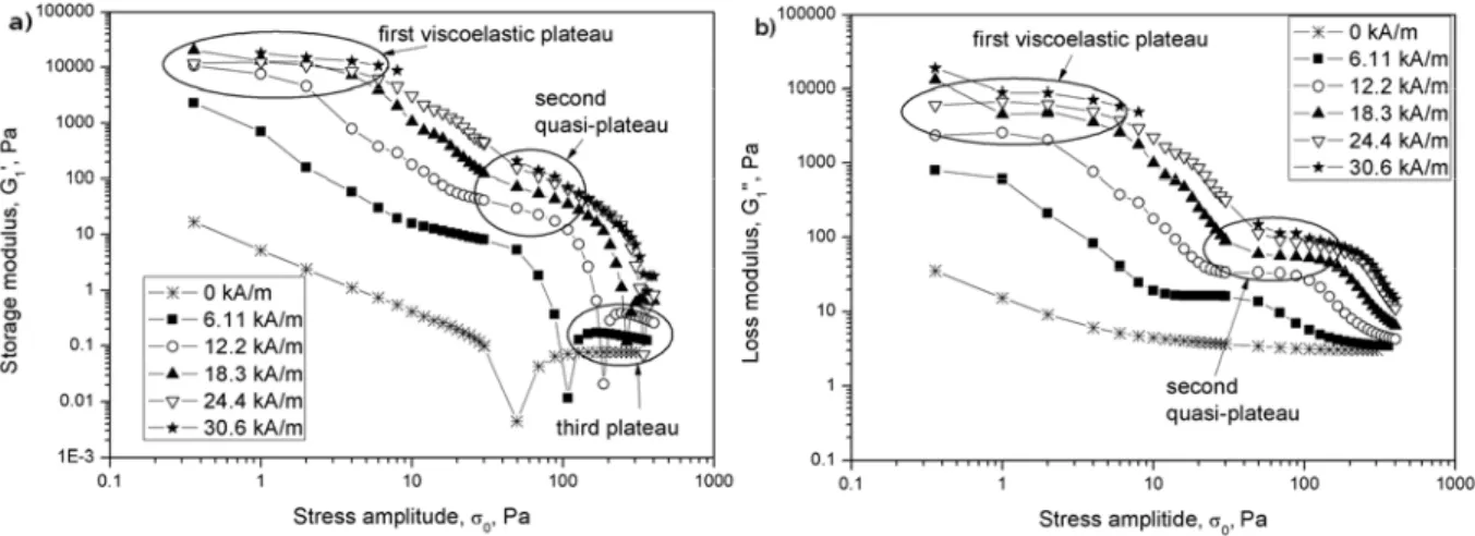
The LAOS tests have been carried out with an MR fluid composed of cobalt fibers at a volume fraction Φ=5%, using a controlled-stress rheometer under an external magnetic field applied perpendicularly to the rheometer plates. Experimental dependencies of the shear moduli, G1’ and G1” (the subscript “1” stands for the first harmonic of the strain response) on
the stress amplitude, σ0, are shown in Fig. 2.8 for the excitation frequency, f=1Hz and for six
values of the external magnetic field, H0. In all cases, both moduli increase with the growth in
the magnetic field intensity and decrease with the stress amplitude. In particular, a short linear viscoelastic plateau at σ0≲1Pa is followed by a rapid decrease of the moduli until a second
quasi-plateau, which is better distinguished for the loss modulus curves. After this second quasi-plateau, there is a second abrupt decrease of the moduli, at the end of which the storage modulus shows the third final plateau after some local minimum.
Fig. 2.8. Experimental stress dependencies of the storage (a) and loss (b) moduli of the fiber suspension at the excitation frequency of 1Hz (with a kind permission from the Journal of Non-Newtonian Fluid mechanics, Elsevier)
The first viscoelastic plateau, which appears only for the magnetic fields
H0≥12.2kA/m, corresponds to the strain amplitudes, γ0, as low as 10-4 – 10-3. At such strains,
the upper plate displacement during an oscillation cycle is as small as 20-200 nm, i.e. much smaller than the fiber’s minor dimension – diameter 2a=4.8µm. Thus, we cannot expect a homogenous deformation of the aggregates, but rather a rearrangement of fibers inside the aggregates accompanied by their microscopic displacement and/or by their elastic bending. The latter could explain high values of the storage modulus at small amplitudes (more than 10 kPa at the particle volume fraction of 5%). The large values of the loss modulus could come from the non-affinity of the fiber displacement on microscopic scale, as pointed out by Klingenberg.46 The first decrease of the storage moduli followed by a second quasi-plateau probably corresponds to a gradual transition from microscopic-to-macroscopic scale deformation of the suspension structure. At the end of this transition, the percolating aggregates are expected to be strained uniformly at small but measurable angles. Actually, at the magnetic field intensity, H0=30.6 kA/m, the second quasi-plateau starts at γ0≈0.1
corresponding to the upper plate displacement of 20µm, which is at least, five times the fiber diameter. This second quasi-plateau is attributed to the second quasi-linear viscoelastic regime governed only by macroscopic deformations of the structure. After a second viscoelastic quasi-plateau (which extends from σ0≈40 Pa to σ0≈100 Pa), a more gradual decrease in shear moduli is caused first by an abrupt increase in oscillation amplitude of the aggregates and, second, by their rupture in response to tensile hydrodynamic forces.
To confirm the above interpretations of the experimental results, we develop a theoretical model, which considers a macroscopic deformation of structures and can only be applied for the stress amplitudes higher than those corresponding to the beginning of the second quasi-plateau.47 Briefly, the theory supposes a coexistence of the aggregates spanning the rheometer gap (percolating aggregates), the aggregates attached by one of the ends to
rheometer wall and the free branches attached by one of the ends to the percolating aggregates (the two latter are called pivoting aggregates). The percolating aggregates move affinely with the rheometer walls and contribute only to the storage modulus of the suspension, while the pivoting aggregates oscillate out of phase with the rheometer walls and contribute to both the storage and loss moduli. Starting from some critical stress amplitude, the percolating aggregates are detached from one of the walls (because of the structure instabilities revealed by simulations) and join to the class of pivoting aggregates. The stress versus shear rate relation is given by the sum of the contributions from percolating and pivoting aggregates, each of them weighed by a volume percentage of the corresponding aggregates. In simulations, we impose a harmonic stress signal, σ( )t =σ0cos(2πf t), with t being the time, and calculate a non-harmonic strain response, γ(t), which is then expanded into Fourier series. The first harmonics of such an expansion gives us the shear moduli G1’, G1”, whose
theoretical stress-dependencies are compared with the experimental ones in Fig.2.9 for
H0=30.6kA/m and the stress σ0>30 Pa corresponding to the beginning of the second
Fig. 2.9. Comparison theory-experiments for the stress-dependence of the shear moduli at the magnetic field intensity, H0=30.6 kA/m and frequency f=1Hz. The fit parameter of the model – the volume percentage of the
pivoting aggregates – is chosen to be φ=0.7. Solid lines correspond to calculations and points – to experimental results (with a kind permission from the Journal of Non-Newtonian Fluid mechanics, Elsevier).
The best correspondence between theory and experiments is achieved for the values of the volume percentage of pivoting aggregates equal to φ=0.7 (accordingly, the volume percentage of the percolating aggregates is 0.3). This parameter is kept the same throughout all our simulations. Nevertheless, in the broad range of φ (0.5<φ<1), the calculated shear moduli differed not more than two times from the values reported in Fig.2.9. As is seen from Fig. 2.9, the storage modulus is subjected to a more drastic decrease than the loss modulus. The crossover of both moduli occurs at σ0≈100 Pa and is well captured by our model. In our calculations, we did not reproduce the small local minimum of the storage modulus at σ0≈350
Pa. A small increase of the storage modulus after this local minimum could occur because of the short-range hydrodynamic interactions and collisions between aggregates, which would restrict the aggregate motion to smaller amplitudes. Note that, apart from this local minimum, both experimental and theoretical curves G1’(σ0), G1”(σ0) are relatively smooth in the whole
range of the applied stresses, thus, the transitions between the different aggregation regimes are not clearly distinguishable in these curves. However, the transition between the regime of coexisting percolating and pivoting aggregates to the regime of purely pivoting aggregates
requires a special attention. At σ0>140 Pa, the solution for the strain γ(t) becomes strongly
asymmetric relative to the equilibrium position, γ=0, which does not have any physical sense. The percolating clusters are considered to be unstable and they are supposed to break in the middle, remaining attached to one of the walls. So, they are transformed into pivoting aggregates, which, according to our calculations, are stable in the broad range of applied stress. Note that this instability is similar to the one, which defines the static yield stress through its maximum versus applied strain.48
Speaking about comparison between the viscoelastic response of fiber suspensions and the suspensions of spherical particles, the experimental results of de Vicente et al.7,10 reveal higher shear moduli of the former at low-to-intermediate magnetic fields, while the difference becomes minor at high magnetic fields, at which the particle magnetization approaches saturation. Such a shape-induced enhancement of the shear moduli can be easily understood in terms of the shape-dependent demagnetization effect discussed in Sec. 2.3. At high magnetic fields, H ∼MS, the demagnetization field vanishes inside both spherical and rod-like particles, and, in the absence of solid friction, the difference in the yield stresses and shear moduli of both suspensions should also vanish, as is apparently the case of smooth nano-sized iron or magnetite particles used by de Vicente et al.7,10 Such an interpretation was originally given by these authors. A significant difference between the yield stresses in our suspensions at high magnetic fields [Sec. 2.2] was interpreted by a rather strong solid friction between our rough micron-sized fibers. In conclusion, a more detailed study is required to elucidate the effect of the particle surface state on the viscoelastic properties of MR suspensions (composed of spheres or fibers).
3. MR fluid flows in longitudinal fields
As already mentioned in Introduction, apart from playing with the particle morphology, one can change the orientation of the magnetic field relative to the flow in order to improve the performance of a given MR smart device. In particular, the use of longitudinal magnetic fields instead of perpendicular ones allows a much more compact design of MR devices, without substantial loss of the MR effect – the yield stress in longitudinal fields appears to be of the same order of magnitude that the one in perpendicular fields, except for suspensions of weakly paramagnetic particles, whose viscosity decreases in longitudinal fields.26 In this Section, we consider shear and pipe flows of a conventional MR fluid in the presence of a longitudinal external magnetic field and give a qualitative explanation of the “longitudinal” MR effect followed by quantitative estimations of the dynamic yield stress.
Obviously, high mechanical stresses in longitudinal fields may only appear if the MR structures are misaligned relative to the fluid streamlines. For instance, if aggregate rotation is
restricted to the shear plane, the aggregate shear stress scales as 2 2 2
0 re cos sin σ η γ∝ < θ θ > [cf. Batchelor49], with θ being an angle between the aggregates and the streamlines, re – the
aggregate aspect ratio, angle brackets denote averaging over all possible orientations. Thus, even a small angle deviation of aggregate orientation from the flow direction may generate a non-negligible stress, if the aggregate aspect ratio is high. Contrarily to flow-aligned aggregates, a misaligned aggregate should have a large but finite length defined by the equilibrium between the tensile hydrodynamic force and the magnetic cohesive force. Thus, the aggregate aspect ratio is expected to follow the same shear rate dependence as in the case of the perpendicular magnetic field, re2 ∝γ−1 [cf. Sec. 2.3]. This condition, verified by our theory, could explain the appearance of the dynamic yield stress in longitudinal fields. The main question now is which mechanism can be responsible for aggregate misalignment. The
main hypothesis of the present study is that the aggregates can deviate from their orientation along the streamlines because of magnetic dipole interactions with the neighboring aggregates. Since the aggregates are randomly spaced in the suspension, under shear flow, they will change their mutual positions and orientations in irregular way. Together with many-body interactions, this may cause a stochastic variation in dipolar forces and torques experienced by the aggregates and could produce some fluctuations in their orientations. This process can be regarded as a magnetically induced rotational diffusion of aggregates, by analogy with Brownian rotational diffusion50 or flow-induced rotational diffusion of elongated particles caused by their collisions or short-range hydrodynamic interactions in sheared suspensions.51,52 Stochastic torques coming from many-body magnetic interactions tend to randomize the aggregate orientation, while a shear flow and a restoring magnetic torque, exerted on aggregates by an external field, tend to align the aggregates with the flow. So, the fluctuations in aggregate orientation are not necessarily large and might not lead to collisions. In this case, we shall deal with a weak rotational diffusion caused solely by long-range dipole interactions. In support of this hypothesis, weak orientation fluctuations have recently been observed in experiments on kinetics of aggregation of diluted magnetic suspensions. These experiments are currently being carried out in our research group and have not been published yet.
Let us now estimate the dynamic yield stress of the MR fluid, whose aggregates are subjected to stochastic angular oscillations under a simple shear in the longitudinal field. The fluctuations of aggregate orientation can be seen as a random walk when the aggregates perform irregular jumps with the mean amplitude ∆θ and the mean jump duration ∆t. The intensity of such fluctuations is measured by a rotational diffusion constant, which, according to the random walk model, scales as [cf. Van de Ven50]:
2 2 ( ) r D t t θ ω ∆ ≈ ∆ ∆ ∼ , (3.1)
where ω2 is the mean square angular velocity of the aggregates. The mean jump duration can be estimated by considering the mutual displacement of two neighboring aggregates (spaced laterally by a distance d) in shear flow: ∆ ∼t 2 /(L γd), where 2L is the aggregate length. The amplitude of orientational fluctuations is measured by a torque, Tint, created by
many-body magnetic interactions with neighboring aggregates and called hereinafter interaction torque. The mean square angular velocity of the stochastic motion of aggregates can be estimated as ω2 ≈ Tint2 / fr2, with Tint2 being the mean square interaction torque and fr – a rotational friction coefficient. Estimating both quantities Tint2 and fr and taking
into account that the latter is proportional to the aggregate aspect ratio squared
( 2 1
r e
f ∝ ∝r γ− ), we show that the rotational diffusion constant is linear in shear rate:28
r
D =Cγ (3.2)
with C – a dimensionless factor proportional to the square of the particle volume fraction Φ. Note, that the same shear rate dependence was postulated by Folgar and Tucker51 for the rotational diffusion of non-Brownian rod-like particles induced by their collisions in sheared suspensions. However, the physics is quite different because, in the latter situation, the random orientional walk was only dictated by the rate of collisions proportional to the shear rate, whereas, in our case, it is the interplay between long range dipolar forces and shear rate, which produces the same scaling.
In order to evaluate the suspension stress, we must first determine the orientation distribution of aggregates, or rather the second and the fourth statistical moments, e ei k and
i k l m
e e e e , intervening into the expression for the stress tensor, where e is the unit vector
along the aggregate major axis and e is its component along the axis Oxi i, i=1,2,3. Here, the
axis Ox1 is aligned with the velocity direction, the axis Ox2 corresponds to the velocity
gradient direction and the axis Ox3 – to the vorticity direction. The quantities e ei k and
i k l m
e e e e can be determined by solving a set of equations describing temporal evolution of
the statistical moments e ei k [these equations are not given here for brevity, the reader may
consult the textbooks of Bird et al.53 and Doi and Edwards54 for more details] coupled with a certain closure relationship between the fourth and the second moments:
(
)
i k l m i k
e e e e = f e e . We choose a quadratic closure approximation, first postulated by Doi and Edwards,54 e e e ei k l m ≡ e ei k e el m , which becomes exact in the limit of perfect alignment of aggregates and whose exactness decreases with decrease in degree of alignment of aggregates. In a steady shear flow considered here, the problem reduces to a system of four algebraic equations for the four unknown quantities, e e1 2 , e12 , e22 , e32 , the first of
which can be seen as a mean sine of the angle between the aggregates and the flow, and the three last – as mean square cosines of the angle that the aggregate makes with the flow, velocity gradient and vorticity, respectively. The aggregate aspect ratio re intervening into
these equations is found from the balance of magnetic and hydrodynamic tensile forces acting on aggregates, in the same way as in the case of fiber suspensions [cf. Sec. 2.3]. In the wide range of magnetic fields and concentrations (H<15 kA/m and Φ<0.3), the problem admits, within the 10% error, an approximate analytical solution, as follows:
2 2 2 0 1 2 2 1 8 a m a H e e f µ χ α⎛Φ ⎞ ≈ ⎜ ⎟ Φ ⎝ ⎠ (3.3a)
4 2 2 2 2 0 2 3 2 1 32 a m a H e e f µ χ α⎛Φ ⎞ = ≈ ⎜ ⎟ Φ ⎝ ⎠ (3.3b) 4 2 2 2 0 1 2 1 1 16 a m a H e f µ χ α⎛Φ ⎞ ≈ − ⎜ ⎟ Φ ⎝ ⎠ (3.3c)
where α is an adjustable parameter, Φ ≈a π / 6 is the internal volume fraction of aggregates with the particles arranged into a simple cubic lattice, χa is the aggregate magnetic
susceptibility, and f is the magnetic force (per unite particle cross-section) acting between m
two particles inside the aggregate. The last two quantities are functions of the external magnetic field H and calculated by numerical simulations of Maxwell magnetostatic equations.
Similarly to the case of fiber suspensions, the shear stress is calculated with the help of the well-known relationships developed for dilute and semi-dilute suspensions of anisotropic particles.42,43 Replacing the aggregate aspect ratio by an appropriate relationship we obtain the final expression for the shear stress (12-component of the stress tensor):
(
)
2 2 2 2 0 1 2 1 0 1 2 2 hydrodynamic magnetic stress aggregate stress solvent stress 2 2 2 2 3 0 1 2 4 2 1 diffusion stress 1 2 2 2 3 2 m a a a a a m a f e e e H e e e H e e f e χ σ η γ χ µ µ χ α ⎛ Φ ⎞ Φ = ⎜ + ⎟+ Φ − ⋅ + Φ Φ + ⎝ ⎠ Φ + Φ (3.4)The first term in the right-hand side of this equation stands for the solvent contribution to the stress and the last three terms stand for the aggregate contribution. Among these three terms, the first one corresponds to the hydrodynamic part of the aggregate stress, the second one comes from the external magnetic torque (magnetic stress) and the last one arises from the random interaction torques inducing random fluctuations of aggregate orientations
[defined by Leal and Hinch55 as diffusion stress]. All the three contributions of the aggregate stress appear to be independent of the shear rate, so, their sum is considered as a dynamic yield stress. Furthermore, analysis shows that the magnetic stress gives a negligible contribution, so the final expression for the dynamic yield stress reads:
(
2 2)
2 2 3 0 1 2 2 1 2 1 4 2 1 hydrodynamic stress diffusion stress 3 2 a m Y m a H e e f e e e f e µ χ σ ≈ Φ + α Φ Φ (3.5)To validate our theory, we have performed a detailed experimental study of magnetic suspension flow in the presence of a longitudinal magnetic field. Because of experimental constraints, experimental realization of simple shear flows with the magnetic field aligned with the fluid streamlines is quite problematic. Therefore, we had to use a pressure-driven flow through a cylindrical channel instead of the simple shear flow studied theoretically. The shear rate varies across the channel in capillary flows. However, using our model, we estimated that the shear rate variation along the aggregates was negligible, except for a narrow central flow region. So, we expect that the rheological behavior observed in the pressure-driven flow should be similar to that in the drag shear flow with a linear velocity profile. The experimental flow curves (not shown here for brevity) obtained for the capillary flow in the longitudinal magnetic field appear to be linear and can be interpolated by a linear rheological law, σ σ ηγ= Y + , similar to the one predicted by our model.
Experimental and theoretical dependencies of the dynamic yield stress, σY, on the
magnetic field intensity are presented in Fig. 3.1 for the magnetic suspensions of different volume fractions. The theoretical dependencies were fitted to experimental ones by using the least square method with a single free parameter, α ≈1.5. As is seen from Fig. 3.1, the yield stress is an increasing function of the magnetic field intensity. The increasing
field-dependence of the yield stress can be easily understood by the two mechanisms, as follows. First, the magnetic interactions between aggregates increase with the increasing magnetic field. This leads to larger fluctuations of aggregate orientation and therefore to a larger viscous dissipation. This mechanism appears in Eq. (3.5) for the yield stress through the statistical moment e e1 2 , which is a growing function of the magnetic field intensity
[Eq.(3.3a)]. Second, magnetic interactions between particles, composing the aggregates, also increase with a growing magnetic field. The aggregates become more resistive against destructive shear forces, their length increases with the field, so, they generate higher stresses.
Fig.3.1. Theoretical and experimental dependencies of the dynamic yield stress of the MR fluid (composed of spherical particles) on the magnetic field strength at different particle volume fractions. Points correspond to experimental data and lines – to the theory. The magnetic field is parallel to the flow direction (with a kind permission from the Journal of Rheology)
Fig.3.2. Theoretical and experimental dependencies of the dynamic yield stress of the MR fluid (composed of spherical particles) on the particle volume fraction for the magnetic field strength H=15 kA/m. The magnetic field is parallel to the flow direction (with a kind permission from the Journal of Rheology)
The concentration dependence of the dynamic yield stress is presented in Fig.3.2 for the magnetic field strength H=15 kA/m. The theoretical values of the yield stress were calculated using the appropriate value of the free parameter, α=1.5. Again, we obtain a reasonably good correspondence with experiments. As is seen from Fig. 3.2, both theory and experiments show that the yield stress increases with the particle volume fraction stronger than linearly. Such nonlinear behavior could be easily explained by concentration-enhanced interactions between aggregates. In more details, the mean distance between aggregates and, consequently, the magnetic interaction torque increase with the particle volume fraction. Therefore, the aggregates will be subjected to stronger fluctuations of their orientation and will generate a stronger viscous dissipation. More quantitatively, the hydrodynamic stress – the most important contribution to the yield stress – is equal to Φfm e e1 2 e12 , with, according to Eqs. (3.5a) and (3.5c), 2
1 1
e ∼ and 2
1 2
e e ∝ Φ . Therefore, the hydrodynamic stress, and consequently the yield stress, varies as 3
Y
σ ∝ Φ . To the best of our knowledge, such a strong concentration behavior has not been observed in magnetic fields perpendicular to the flow. This is likely because, in perpendicular fields, the MR response of the suspension
is mostly governed by the magnetic interaction between aggregates and external field (which results in a high restoring torque), whereas, in longitudinal fields, the MR effect is produced by relatively strong dipolar interactions between aggregates.
4. Concluding remarks
In this Chapter, we reviewed recent experimental and theoretical results on the magnetorheology of fiber suspensions in magnetic fields perpendicular to the shear as well as of suspensions of spherical particles in longitudinal magnetic fields. Both these problems, weakly related to each other at the first sight, reveal essentially similar physics. Upon magnetic field application, both spherical particles and fibers form strongly elongated aggregates exhibiting a similar behavior in shear flows. The two types of aggregates tend to align with the streamlines, they are progressively destroyed by the shear forces at increasing shear rates and resist to these forces thanks to magnetic interactions between their constitutive particles. The differences lie in (1) a stronger magnetic permeability of the aggregates of fibers; (2) a presumably stronger solid friction between fibers; and (3) eventually a more sparse structure of the aggregates of fibers. Such differences between the aggregates composed of fibers and spheres lead to a non-similar MR response of both suspensions: in most of the cases, a few times enhancement of the yield stress and shear moduli was reported for fiber suspensions by different research groups, at least for the magnetic fields below the magnetization saturation limit of particles.7,8,11,17
The particle shape effect on the magnetic permeability enhancement is commonly recognized to be the major effect contributing to a stronger MR response of fiber suspensions, at least in steady shear flows at Mason numbers, Mn>1 and at low-to-moderate magnetic
fields, H<50 kA/m [cf. de Vicente et al.7 ,Gómez-Ramírez et al.15]. As the magnetic field increases, demagnetizing fields inside particles decrease and their magnetization approaches a saturation value, which is almost the same for both spheres and fibers. So, at high magnetic