HAL Id: emse-01109140
https://hal-emse.ccsd.cnrs.fr/emse-01109140
Submitted on 24 Jan 2015
HAL is a multi-disciplinary open access
archive for the deposit and dissemination of
sci-entific research documents, whether they are
pub-lished or not. The documents may come from
teaching and research institutions in France or
abroad, or from public or private research centers.
L’archive ouverte pluridisciplinaire HAL, est
destinée au dépôt et à la diffusion de documents
scientifiques de niveau recherche, publiés ou non,
émanant des établissements d’enseignement et de
recherche français ou étrangers, des laboratoires
publics ou privés.
Practical measurements of data path delays for IP
authentication & integrity verification
Ingrid Exurville, Jacques Jean-Alain Fournier, Jean-Max Dutertre, Bruno
Robisson, Assia Tria
To cite this version:
Ingrid Exurville, Jacques Jean-Alain Fournier, Jean-Max Dutertre, Bruno Robisson, Assia Tria.
Prac-tical measurements of data path delays for IP authentication & integrity verification. Reconfigurable
and Communication-Centric Systems-on-Chip (ReCoSoC), 2013 8th International Workshop on, Jul
2013, Darmstadt, Germany. �10.1109/ReCoSoC.2013.6581551�. �emse-01109140�
Practical measurements of data path delays for
IP
authentication & integrity verification
Ingrid Exurville
∗, Jacques Fournier
∗, Jean-Max Dutertre
†, Bruno Robisson
∗, Assia Tria
∗∗CEA,†EMSE
Gardanne, France
{ingrid.exurville, jacques.fournier, bruno.robisson, assia.tria}@cea.fr {dutertre}@emse.fr
Abstract—This paper describes the results of the practical measurements done to determine the path delay associated with each bit of a hardware AES FPGA implementation using a clock glitch injection tool. We illustrate how the measured path delays can constitute a characteristic fingerprint of an Intellectuel Property (IP) and can be used to detect the insertion of hardware trojans. The influence of synthesis options and inter die variations on the measurements is also studied. Compared to trojan detection schemes based on path delay characterisations already proposed in the literature, our approach does not require any additional test circuit to be inserted in theIP. Moreover our results are based on practical measurements.
I. INTRODUCTION
The authenticity and integrity of hardware modules has become a hot topic lately, in particular for security-related applications. The first phenomenon justifying this is the de-localisation of production facilities: even though a particu-lar design is specified and implemented within one’s own premises, the manufacturing of the hardware chip might be done in some (far away) different facility being less security-stringent leading to one having doubts on whether the chip sent back is the original design or whether a trojan has not been inserted into the original design. The second phenomenon is the “de-materialization” of hardware designs due to the advent of cheap and powerfulFPGAs. The design of complex systems for such programmable devices might involve the integration of several blocks (or IPs) from different design houses. End users of such systems might want to make sure that the critical blocks (like encryption machines) used in the end system is actually the one coming from a trusted/certified provider and that it is not a rogue functional copy or that it has not been modified through the insertion of a trojan.
In this paper we illustrate how measured path delays can constitute a characteristic fingerprint of a IP and be used to detect the insertion of hardware trojans. We describe the results of the practical measurements done to determine the path delay associated with each bit of a hardware AES FPGA
implemen-tation using a clock glitch insertion tool. The influence of synthesis options and inter die variations on the measurements is also studied. Our scheme is based on practical measurements and does not require the addition of any dedicated circuitry in the IP under test.
This paper is organised as follows: we first review the principles already proposed for authenticating and verifying the integrity of integrated circuits (or IPs), with a focus on
the use of path delays for detecting hardware trojans. Next
we describe our design under test, a straight forward hardware implementation of the AESencryption algorithm and some of the trojans devised for our measurements. The practical set-up used is then detailed and the practical results obtained are covered. Then we conclude with a discussion on the potential of our proposed scheme.
II. INTEGRITY FOR IP VERIFICATION
We shall use the term Intellectual Property (IP) to refer to the implementation of some mathematical functionality or state machine, designed using some hardware abstraction language (VHDL, Verilog, etc.) that is intended to be embedded into an
FPGA(The FPGA target is the main target of our study) or to be synthesized into some integrated circuit (IC) technology.
A hardware trojan is composed of two parts, the trigger and the payload [1]. The trigger is the mechanism that determines the condition under which the ‘malicious’ effect of the trojan should start. The trigger can either be generated externally (external signal or a special external physical condition) or internally (internal state of theIC, special data configurations, etc.). Moreover the trigger can either be combinational where the sought condition is the result of a logical operation among several signals or sequential where the signal is generated by a state machine. The payload is the ‘malicious’ effect of the trojan: it can either be explicit where signals or logic blocks are directly added, removed or de-activated [2] or implicit where the effect cannot be directly observed like, for example, the thinning of particular wires or hiding information into one of the side channels of the IC [3].
Most research works have indeed focused on the detection of trojans. Detecting trojans is a complex, multi-dimensional problem which depends on the type of the trojan (functional or parametric), its size, its distribution over the IC’s surface and its structure. A taxonomy for detecting trojans is proposed in [4]. Apart from classical ICanalysis techniques either based on Failure Analysis or on ATPG (Automatic Test Pattern Generation) which are limited in terms of coverage of the IC, novel techniques have been proposed. For example side chan-nels have been studied in [5], [6]. However such techniques are limited by the size of the trojan with respect to the IC
under analysis. More sophisticated region-based analyses have been proposed in [7]. In [2], the authors propose a method of detecting trojans by measuring the delay paths of a DES circuit.
Althought there is framework which does not require a
Reconfigurable and Communication-Centric Systems-on-Chip (ReCoSoC), 2013 8th International Workshop on http://dx.doi.org/10.1109/ReCoSoC.2013.6581551
golden IC [8], most of the techniques proposed in the literature rely on the availability of a “golden reference”. The “golden reference” is an implementation of the IC which is trojan-free and onto which the reference side-channel or delay path measurements are made and later used as a reference when implementing the trojan detection scheme onto other instantiations of theIC. Such a “golden” is only available once the circuit has been fabricated and totally reverse-engineered (which is an expensive and time consuming process) to make sure that it contained no trojan.
III. USE OF PATH DELAYS’MEASUREMENTS AS AN IP’S FINGERPRINT
Lately, several research papers have proposed schemes for detecting trojans based on the measurement of path delays within anIC. The use of “shadow registers” is very widespread. In [9], the “shadow registers” worked with a “shadow clock” which runs at the same frequency as the main clock. A ajustable phase offset permits to measure path delays along an arbitrary large number of paths in the design. In [10], the authors propose a mechanism where “shadow registers” are added to a given set of critical data paths. Those “shadow registers”, whose sampling times are monitored via a dedicated clock signal, are used to measure the associated delay path: if a trojan is present on this particular path, then the measured delay path is expected to be different from the data path without trojan. By extending this principle to several data paths and by considering that the monitoring of the sampling time of each “shadow register” as a Challenge, then the ICcan be authenticated through a PUF-like challengeresponse pairCRP. A similar philosophy is proposed in [11] where existing test structures are modified to introduce “embedded test structures” that detect delay anomalies introduced by a trojan.
A detection of trojans based on path delays without ad-ditional circuitry is discussed in [2]: the measurement of the path delays corresponding to each of the 64 bits of the DES ciphertext are determined by simulation.
In this paper, we pushed forward the principle lain in [2] to show that the path delays associated with the data bits of an IC running an encryption algorithm like the AES can be measured in practice and can be used to detect modifications within the circuit. Our first contribution is to perform concrete measurements of the path delays associated with individual bits of the principal data path. The main advantages and differentiators of using this technique are the following:
• We only require an access to the clock of the targeted
IP and to the inputs and outputs of its principal
data path. We do not need any additional circuit or modification of any existing scan chain.
• We do not actually determine the delay incurred by the longest path of theIPbut the delay corresponding to each bit of the longest data path.
• The trojans don’t need to be activated for being detected by our scheme.
IV. DEVISING PROOF-OF-CONCEPT TROJANS FOR A HARDWARE AES
To investigate about our proposed methodology, practical clock glitch injections were done on a hardware AES
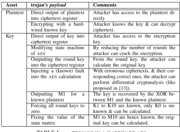
imple-Asset trojan’s payload Comments Plaintext Direct output of plaintext
into ciphertext register
Attacker has access to the plaintext di-rectly.
Encrypting with a hard-wired known key
Attacker knows the key & can decrypt ciphertext.
Key Direct output of key into ciphertext register
Attacker has access to the encryption key.
Modifying state machine ofAES
By reducing the number of rounds the attacker can crack the encryption. Outputting the round key
into the ciphertext register
From the round key, the attacker can calculate the original key.
Injecting a (known) fault into theAEScalculation
With erroneous ciphertexts, & their cor-responding correct ones, the attacker can perform differential cryptanalysis (like proposed in [13]).
Outputting M1 for a known plaintext
The key is recovered by the XOR be-tween M1 and the known plaintext. Forcing all round keys to
zero
K1 to K10 are known, only K0 is un-known & can be calculated. Fixing the value of the
state matrix
M1 to M10 are hence known, the orig-inal key can be calculated.
TABLE I. TROJANS IN A HARDWARE AES
mented inVHDLand synthesized for and tested on a SpartanIII
FPGA. TheAESis a standard established by the NIST [12] for symmetric key cryptography.
A. Trojan definitions for AES
In our use case, we view the AES block as an IP where we only have access to the inputs (plaintext, key), outputs (ciphertext) and configuration bits (start, process end). We hence do not cover trojans that use covert channels like the power consumption or electromagnetic emissions to convey sensitive information out the chip [3]. In order to exhaustively search for the trojans that could be implemented on such an
AES IP, we performed a security analysis of such a design. Two main asset were identified:
• The plaintext is an asset in the case theAES IPis used to protect the confidentiality of data. The attacker may want to insert a trojan that would output the plaintext itself instead of the ciphertext and hence have access to any sensitive data that was meant to be encrypted by the AES IP.
• The key is the secret that is used by the AES IP to encrypt/sign the plaintext. An attacker might want to output the secret key in order to then be able to decrypt the ciphertext.
Table I summarizes how the above assets could be output by a trojan. Note that the table only looks at the payload of the trojan and not its trigger as there are in our opinion too many different possibilities of the later.
B. Description of implemented trojans [14]
We implemented two kinds of trojans inserted at RTL level. Both of them have the same trigger. The activation mecanism of the trojan relies a specific plaintext sent externally.
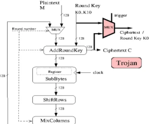
• The first one allows us to directly have the key K0 instead of the ciphertext (Figure 1). We inserted a multiplexer into the AES block. When the trigger is activated, the key is written into the ciphertext register. • The second one gives the subkey K10 instead of the ciphertext (Figure 2). To do so the state matrix
is zeroed at the tenth round in the AddRoundKey transformation. Thus, insofar as this step is composed of an XOR operation between the State matrix and the subkey K10, we get K10 in place of the ciphertext.
Fig. 1. First trojan implemented: AES HT1.
Fig. 2. Second trojan implemented: AES HT2.
Each of the above trojans’ only add less than 3% to the number of slices occupied by our originalAESimplementation. From now on AES INT shall refer to the original AES without trojan, AES HT1 to the AES with the first trojan and AES HT2 to the AES with the second trojan.
V. MEASUREMENT TOOL&SET-UP USED
Clock glitches are a well known fault injection means that endanger data integrity of secure circuits [15]. However, it can also be turned into a path delay measurement tool used to detect hardware trojans. We used a clock glitch generator similar to the one presented in [16] and [17] to allow such measurements. In this section, the basics of timing constraints and how their violation may be used to measure path delays are given. Next we show how the uncertainty of the measurement may be almost nullified. The device under test is described. Finally, the way we have conducted measurement experiments is reported.
A. Principle of path delay measurement with clock glitches Data is released from the first register bank on a clock rising edge and then processed through the logic before being latched into the next register bank on the next clock rising edge. Thus, in a first approximation the clock period (Tclk) has
to be longer than the maximum data propagation time through the logic (DpM ax) to ensure correct operation. Besides, a
precise writing of the timing constraint equation requires to take into account three other parameters: Dclk2q the delay between the clock rising edge and the actual update of a register’s output; Tskewthe skew or slight phase difference that
may exist between the clock signals at the clock’s inputs of two different registers; Tsetup the set-up time which is the amount
of time for which a D flip-flop input must be stable before the clock’s rising edge to ensure reliable operation. There also exists a hold time (Thold) which expresses the same constraint
but after the clock edge. Hence, the timing constraint equation (eq. 1) is obtained:
Tclk> Dclk2q+DpM ax+Tsetup− Tskew (1)
A set-up time violation arises if the last signal transition is too close to the clock’s rising edge. Then theDFF’s output goes into a metastable behaviour [18]: it may stabilize either on a high or low state generating an error or not. Consequently the violation of the timing constraint is a straightforward means to inject faults into a circuit. This may be achieved by reducing progressively the clock period (a so called clock glitch) until a setup time violation occurs.
B. Delay measurements model
As mentioned above, path delay measurement is not deter-ministic. However, we developed a measurement methodology intended to reduce this uncertainty. Several measurements are done with the same experimental settings. These measurements lie within the interval limited by Tsetup+Thold, arranged in
what we call a timing distribution. Moreover, provided that there is enough measurements (a few thousands as revealed by our experiments) they feature a Gaussian-like shape. Using GNU Octave tool [19], we approximated these distributions with Gaussian curves and saw that these approximations fitted well in all cases. One of these approximated Gaussian is depicted in Figure 3.
Fig. 3. Distribution for bit 32 of State matrix
This allowed us to choose to represent the distribution corresponding to each measured path delay by the mean of the best fitted Gaussian curve.
C. Description of the device under test
As explained before, we have chosen a programmable circuit (FPGA) running theAES algorithm as a test vehicle to conduct this study. The test chip’s nominal clock period is 100 MHz, and its core nominal voltage is 1.2V. As the delays in the encryption module are greater than the delays in the cipher’s
other modules we can assume that the encryption module will be faulted before any other module (FSM, UART, ...). Hence, the path delays of the encryption module will be measured first by using clock glitches. These path delays will be used in our trojan detection methodology.
The set-up and hold times of the device’sDFFs have mini-mum values of 180ps and zero respectively (for a speed grade -5 component). Hence, the minimal measurement’s uncertainty is 180ps. Note that, the width of the Gaussian’s bottom in Figure 3 is around 200ps which is close to the measurement’s uncertainty.
D. Measurement experiments
In our implementation, an AES round is executed in one clock cycle. For every bit in the cipher block, the propagation delay varies depending on the data processed. Thus the critical path may change at each clock cycle. Path delay measurements were consequently done with the same plaintext and key in order to obtain fair comparisons between the tested ICs. A measurement series is done by progressively reducing the clock period during the 10th AES round by steps of 35ps until
it becomes too short to comply with the timing constraints. Hence, the value of the ciphertext stored in the register is corrupted. As a consequence, a progressive increase of the stress applied (i.e. the stepwise reduction of the clock period) successively induces an increasing number of faults into the longest paths. At the bit level, the clock period related to the first fault occurrence is then recorded for every bit to build the aforementioned timing distributions. As enough measurements are achieved, the corresponding Gaussian curves are calculated and the mean path delay of every faulted bit is retrieved.
Note that for some bits, which we shall call the ghost bits, measurement errors occurred and no associated measured path delays were available. The reason for this is that for such bits, at some point, the generated glitch corrupted the state machine of the AES in addition to the data path resulting in the chip not responding: this of course is an artefact due to our measurement tool, artefact which, as we shall discuss later, might provide useful information in the end.
VI. PRACTICAL RESULTS
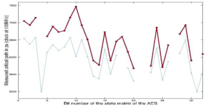
For a constant plaintext (all ones) and a known constant key, we ran 4000 tests whereby for each test the clock glitch is increased by steps of 35 ps and the resulting corrupted ciphertext recorded and analysed (We determined which bit/s of the State matrix has/ve been corrupted [16]). For each test, one or several bits of the measured ciphertext is corrupted and for each of those bits the corresponding number of steps (which gives the duration of the clock glitch, which in turn gives the associated delay path) is recorded as a measured path delay (MPD). Hence for each of the 128 bits, we have a distribution of measured delay paths as shown in Figure 3 for the AES INT.
A. Distribution of measured path delays for all 128 bits We also chose to have a graphical representation where we represent the mean (associated with the Gaussian ap-proximation as explained earlier) of the measured path delay associated with each bit of the State matrix of the AES. Such
a representation (Figure 4) gives a characteristic picture of the
MPDs associated with each bit of theAESState Matrix, along with a distribution of the ghost bits (In our representation, we tried to have a “curve” linking the values of each bit’s MPD,
but could not show values for ghost bits resulting in the curve being discontinuous) relative to our measurement tool. Such a representation shall be called measured path delays’ - MPD -distributions.
Fig. 4. Distribution for the first 32 bits for two different keys and plaintexts
B. Factors impacting the measurements of the MPDs
When performing such measurements, several factors influ-ence the measured propagation time for each bit of the State matrix:
• The value of the chosen plaintext and key: in our experiment we kept the value of the key and plaintext constant (Figure 4).
• The external physical conditions like temperature, voltage, etc.: this aspect was covered. Voltage glitchs have the same effect as clock glitches. The minor variation of the voltage and the temperature has no significant effect on the measurements done. The experiments were performed at room temperature with almost no fluctuations in the voltage supplied [20]. • The VHDL code of the IP: Our measurements showed
that recompiling a sameVHDLcode, while keeping all
synthesis options the same, generated MPD’s distribu-tions which were the same showing that this factor shall have no effect on our trojan detection scheme. • Synthesis options: We looked at the effect of
playing with synthesis options like the KEEP HIERARCHY[21]. As expected when this option was switched on, on average, theMPDassociated with each bit was longer but at the same time, the path delays’ distribution was also modified. This phenomenon is illustrated in Figure 5.
• The FPGA: due to “inter-die” process variations, we expected to have to subtle variations in propagation times for a same bitstream being run on different dies of the sameFPGA. For doing so, we had four different SpartanIII boards (labelled B1 to B4) onto which we loaded the sameAES INTbitstream and performed the measurements. The dispersion phenomenon observed is illustrated in Figure 6 for bit 32 of the State matrix (similar trends are observed on the other bits). The mean path delay associated with each bit is hence shifted when the same bitstream is transported from one board to
Fig. 5. Distribution for the first 32 bits without (thick brown line) & with (thin blue line) KEEP HIERARCHY
Fig. 6. Distribution for bit 32 of State matrix on four different boards
another. This phenomenon is better illustrated by looking at the MPDs’ distributions for all 128 bits. (We only show the first 32 bits in figure 7 for a matter of clarity, but this presented behaviour is the same for the 128 bits of the State matrix): the “orders of appearances” are the same, the ghost bits are the same, with just the ‘curves’ being shifted vertically. Furthermore, this figure emphasizes the differences between the used boards despite our Gaussian approximation. Experiments showed that the inter-die variability was always limited to a 300ps range. Futhermore, due to the change of delay caused by the synthesis, the gaussian model allows us to observe easily the differences between the curves.
Fig. 7. Path delays for first 32 bits of the State matrix on 4 different boards
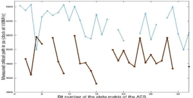
C. Impact of the hardware trojans
The same measurements were done on the IP AES HT1. Then we compared theMPDs distributions of theAES INTand that ofAES HT1 on the same board B1 (Figure 8 (For a matter
of clarity, we only show the first 32 bits but the trend is the same for all 128 bits of the State matrix.)): we not only see that the mean path delay associated with each bit has significantly changed but also that their “orders of appearances” and the distribution of the ghost bits have also been changed.
The modification in theMPDs’ distribution incurred by the
Fig. 8. Path delays distributions without (thick brown line) & with (thin orange line) trojan for the first 32 bits of the State matrix
addition of the trojan (in this case modification of the VHDL
code) is more important than that incurred by simply porting a same bitstream from one board to another. On a bit level, this is illustrated in Figure 9 where, for the bit 32 of the state matrix, on the left we have the four measurements for AES INT on four different boards and on the right we have measurements made on the same boards withAES HT1. This shows that this tool is able, at least for the four samples we had, to detect a significant change in the VHDL code beyond the variations incurred by inter-die variations (Figure 10). Of course, this needs to be confirmed on a much larger set of samples.
Fig. 9. Path delay measured for bit 128 on 4 boards without (left) and with (right) trojan.
Fig. 10. Path delay distributions for the first 32 bits on 4 boards without (thick brown line) & with (thin orange line) trojan.
With respect to synthesis options (KEEP HIERARCHY option in our case), measurements showed that in each of the cases where the option was activated or deactivated, the measured MPDs’ distributions were significantly modified by the presence of the trojan showing that the activation of such an option does not reduce the detectability capacity of our approach (Figure 11) even when the KEEP HIERARCHY option is set.
Fig. 11. Path delay distributions for the first 32 bits with KEEP HIERARCHY without (thick blue line) & with (thin green line) trojan
to AES HT1 only as similar behaviours were obtained with AES HT2.
CONCLUSION&DISCUSSION FOR FUTURE WORK
In this paper we illustrated how a tool used to inject clock glitches into a cryptographic module can be used to perform practical measurements of the mean path delay corresponding to each bit of the principal data path of an AES IP. The distribution of those propagation times is a characteristic “fingerprint” of the module, suggesting that this might be a practical means of authenticating a IP. Moreover since this distribution is influenced by the addition of trojan horses, it might also be used to qualify the integrity of a given IP, without adding any other circuit to the IP. In this paper, this “characteristic fingerprint” consists in visually comparing
MPD distribution curves. Future work shall consist of giving
a quantitative aspect of this “characteristic fingerprint”, such as looking at the classification of the different bits in order of increasing or decreasing propagation times or the distribution of the “ghost bits”or even at the correlation between the curves corresponding to the mean path delays. More experiments shall also be conducted using other types of trojans. Our approach could also be the base for devising a method/tool that would automatically introduce in a given sensitive IPsome test chain that would give end users a (secure) access to a clock PIN and the IP’sIOs to perform such characterisations and authenticate and verify the IP under test. Ultimately we shall see if the
MPDs can be constructed by simulation which could get rid of the “golden reference” problem.
ACKNOWLEDGMENT
This work is supported by the DGA (D´el´egation G´en´erale de l’Armement, Paris, France) and the HOMERE project (Hardware trOjans : Menaces et robustEsse des ciRcuits In-tEgr´es, FUI 14).
REFERENCES
[1] Y. Jin, N. Kupp, and Y. Makris, “Experiences in hardware trojan design and implementation,” in Hardware-Oriented Security and Trust, 2009. HOST ’09. IEEE International Workshop on, july 2009, pp. 50 –57. [2] Y. Jin and Y. Makris, “Hardware trojan detection using path delay
fingerprint,” in Proceedings of the 2008 IEEE International Workshop on Hardware-Oriented Security and Trust, ser. HST ’08. Washington, DC, USA: IEEE Computer Society, 2008, pp. 51–57.
[3] L. Lin, W. Burleson, and C. Paar, “Moles: malicious off-chip leakage enabled by side-channels,” in Proceedings of the 2009 International Conference on Computer-Aided Design, ser. ICCAD ’09. New York, NY, USA: ACM, 2009, pp. 117–122. [Online]. Available: http://doi.acm.org/10.1145/1687399.1687425
[4] X. Wang, M. Tehranipoor, and J. Plusquellic, “Detecting malicious inclusions in secure hardware: Challenges and solutions,” Hardware-Oriented Security and Trust, IEEE International Workshop on, vol. 0, pp. 15–19, 2008.
[5] D. Agrawal, S. Baktir, D. Karakoyunlu, P. Rohatgi, and B. Sunar, “Trojan detection using ic fingerprinting,” in Security and Privacy, 2007. SP ’07. IEEE Symposium on, may 2007, pp. 296 –310.
[6] R. Rad, J. Plusquellic, and M. Tehranipoor, “Sensitivity analysis to hardware trojans using power supply transient signals,” in Proceedings of the 2008 IEEE International Workshop on Hardware-Oriented Secu-rity and Trust, ser. HST ’08. Washington, DC, USA: IEEE Computer Society, 2008, pp. 3–7.
[7] M. Banga and M. Hsiao, “A region based approach for the identification of hardware trojans,” in Hardware-Oriented Security and Trust, 2008. HOST 2008. IEEE International Workshop on, june 2008, pp. 40 –47. [8] M. Li, A. Davoodi, and M. Tehranipoor, “A sensor-assisted self-authentication framework for hardware trojan detection.” in DATE, W. Rosenstiel and L. Thiele, Eds. IEEE, 2012, pp. 1331–1336. [Online]. Available: http://dblp.uni-trier.de/db/conf/date/date2012.html# LiDT12
[9] D. Rai and J. Lach, “Performance of delay-based trojan detection techniques under parameter variations,” in Proceedings of the 2009 IEEE International Workshop on Hardware-Oriented Security and Trust, ser. HST ’09. Washington, DC, USA: IEEE Computer Society, 2009, pp. 58–65. [Online]. Available: http://dx.doi.org/10.1109/HST. 2009.5224966
[10] J. Li and J. Lach, “At-speed delay characterization for ic authentication and trojan horse detection,” in Hardware-Oriented Security and Trust, 2008. HOST 2008. IEEE International Workshop on, june 2008, pp. 8 –14.
[11] C. Lamech and J. Plusquellic, “Trojan detection based on delay vari-ations measured using a high-precision, low-overhead embedded test structure,” in Hardware-Oriented Security and Trust (HOST), 2012 IEEE International Symposium on, june 2012, pp. 75 –82.
[12] NIST, “Specification for the Advanced Encryption Standard,” Federal Information Processing Standards, Tech. Rep. FIPS PUB 197, Novem-ber 26 2001.
[13] S. Ali, R. Chakraborty, D. Mukhopadhyay, and S. Bhunia, “Multi-level attacks: An emerging security concern for cryptographic hardware,” in Design, Automation Test in Europe Conference Exhibition (DATE), 2011, march 2011, pp. 1 –4.
[14] “Hardware trojan taxonomy,” accessed Dec, 2012. [Online]. Available: https://www.trust\-hub.org/taxonomy
[15] M. Yoshikawa and T. Tsukadaira, “A hardware trojan for cryptographic countermeasure circuits,” Lecture Notes in Engineering and Computer Science, vol. 2203, no. 1, pp. 680–684, 2013.
[16] M. Agoyan, J.-M. Dutertre, D. Naccache, B. Robisson, and A. Tria, “When clocks fail: on critical paths and clock faults,” in Proceedings of the 9thSmart-card Research and Advanced Application Conference (CARDIS’98), J.-L. L. Julien Iguchi-Cartigny, Dieter Gollmann, Ed., vol. LNCS, no. 6035. Germany: Springer-Verlag, April 14-16 2010, pp. 182–193.
[17] S. Endo, T. Sugawara, N. Homma, T. Aoki, and A. Satoh, “An on-chip glitchy-clock generator for testing fault injection attacks,” J. Cryptographic Engineering, vol. 1, no. 4, pp. 265–270, 2011. [18] J. Horstmann, “Metastability behavior of cmos asic flip-flops in theory
and test,” IEEE journal of solid-state circuits, vol. 24, no. 1, pp. 146– 157, 1989.
[19] “Gnu octave,” accessed Oct. 5, 2012. [Online]. Available: http: //www.gnu.org/software/octave/
[20] J.-M. D. L. Zussa, J. Cldierre and A. Tria, “From physical stresses to timing constraints violation,” in Forth International Workshop on Constructive Side-Channel Analysis and Secure Design, 2013. [21] “Synthesis options (xst),” accessed Oct. 5, 2012. [Online].
Available: http://www.xilinx.com/support/documentation/sw\ manuals/ xilinx11/pp\ db\ xst\ synthesis\ options.htm