HAL Id: cea-01807027
https://hal-cea.archives-ouvertes.fr/cea-01807027
Submitted on 4 Jun 2018
HAL is a multi-disciplinary open access
archive for the deposit and dissemination of
sci-entific research documents, whether they are
pub-lished or not. The documents may come from
teaching and research institutions in France or
abroad, or from public or private research centers.
L’archive ouverte pluridisciplinaire HAL, est
destinée au dépôt et à la diffusion de documents
scientifiques de niveau recherche, publiés ou non,
émanant des établissements d’enseignement et de
recherche français ou étrangers, des laboratoires
publics ou privés.
Split of Composite Components for Distributed
Applications
Ansgar Radermacher, Önder Gürcan, Arnaud Cuccuru, Sébastien Gerard,
Brahim Hamid
To cite this version:
Ansgar Radermacher, Önder Gürcan, Arnaud Cuccuru, Sébastien Gerard, Brahim Hamid. Split of
Composite Components for Distributed Applications. Languages, Design Methods, and Tools for
Electronic System Design. Lecture Notes in Electrical Engineering, 311, pp.265-280, 2014, Lecture
Notes in Electrical Engineering. �cea-01807027�
Abstract Composite structures as in UML are a way to ease the development of complex ap-plications. Composite classes contain sub-components that are instantiated, interconnected and configured along with the composite. Composites may also contain operations and further attributes. Their deployment on distributed platforms is not trivial, since their sub-components might be allo-cated to di↵erent computing nodes. In this case, the deployment implies a split of the composite. In this chapter, we will motivate why composites need to be allocated to di↵erent nodes in some cases by examining the particular case of interaction components. We will also discuss several options to achieve the separation and their advantages and disadvantages including modeling restrictions for the classes.
14.1 Introduction
The basic idea behind any component-oriented approach is that elementary application pieces (i.e. components) can be composed together in order to achieve the functionality of a more complex system. Component-oriented approaches are usually grounded on a design process including component development or reuse, assembly and deployment.
In thecomponent assembly step, the system under design is itself considered as a component. It is hierarchically defined by an assembly of existing components using an Architecture Description Language (ADL) [4], where the assembly is concretely specified by connections expressed between sub-components (parts). In the context of this chapter, we focus on Unified Modeling Language (UML) [16] as modeling language. Sub-components can themselves be defined as assemblies, resulting in hierarchical systems of arbitrary depth.
In thedeployment specification step, the target execution platform for the application is con-sidered. The model of the execution platform usually consists, at least, of an identification of the various execution nodes, as well as available communication paths between them. The deployment specification consists of allocating the components of the application model to execution nodes of the platform (often indirectly by allocating them to processes or threads which in turn are allocated Ansgar Radermacher, Önder Gürcan, Arnaud Cuccuru, and Sébastien Gérard
CEA, LIST, Laboratory of Model driven engineering for embedded systems, Point Courrier 174, Gif-sur-Yvette, F-91191 France, e-mail: {firstname.lastname}@cea.fr
Brahim Hamid
IRIT, University of Toulouse, France e-mail: [email protected]
to execution nodes, but we simplify this aspect in the context of this chapter). Allocation is usually done taking into account non-functional requirements of the system under design, such as execution time constraints, memory footprint, communication throughput, etc.
It is sometimes necessary to allocate sub-components to di↵erent execution nodes which requires a split of the associated composite. The next section illustrates this problem by means of a small example, section 14.3 provides multiple options how to split composites. Section 14.4 examines how existing component frameworks split composites. An evaluation and comparison of these options is given in section 14.5. Section 14.6 concludes this chapter.
14.2 Motivating Example
In this section, we motivate why some composites need to be split by examining interaction components.
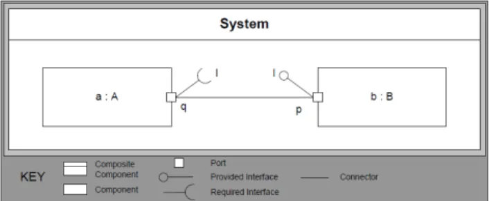
Consider a very simple application with two components, A and B as shown in Fig. 14.1. A has a port q with a required interface I, B has a port p with a provided interface I.
Fig. 14.1 A simple system with two components and uni-directional communication.
Now consider that the communication between A and B is realized by a component that im-plements the interaction on top of the operating system’s socket API. We call such a component an interaction component (also called connector in the context of the DDS-for-CCM specification [15]). On a logical level, this component is a single entity that may contain configuration data such as a port number, connection policies or a unique identifier (object reference).
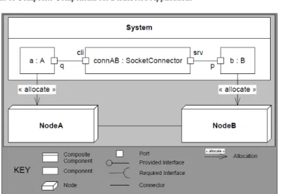
If we want to distribute the application onto two nodes, a and b are allocated to di↵erent nodes. Fig. 14.2 shows the architecture of the example system. Please note that the composite structure diagram distinguishes between a role (corresponding to a kind of instance) and its type, i.e. the socket is not a nested classifier within the system but a part of the system on an instance level. Thus, the first component that is split is the component representing the system itself (System). However, the System component is a particular case, since there exists only one instance, it has no behavior of its own and there are no connections from the system boundary to inner parts (called delegation connectors in UML [16]). Thus, it is a pure assembly component and basically used to define the instances of a system and their interconnections.
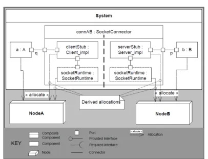
Fig. 14.3 shows the internal structure of the SocketConnector component. It consists of a client and server stub (cli and srv respectively) which both access a socket run-time. The dashed outline of the latter indicates that this component is shared: it is not instantiated along with SocketConnector but exists independently. The access to a shared resource within a composite corresponds to a
Fig. 14.2 Distribution of the system given in Fig. 14.1. The System composite component is now with sockets and allocation.
Fig. 14.3 Internal structure of the SocketConnector composite component given in Fig. 14.2.
kind of vertical connection: the communication of the stubs with the run-time is a communication between di↵erent layers, pre-assembled within the composite.
Since the communication with the interaction component is a simple local communication, the interaction component itself needs to be separated. We can further follow local connections within the connector to determine the allocation of the internal parts of the connector. The allocations within the socket connector can thus be derived from the allocations of the application components: the client fragment of the connector needs to be co-located with A and the server fragment with B. An interesting aspect is the socket run-time that is shared by client and by server fragment. Whereas it exists only once from a logical viewpoint, it must be present on each node and thus be allocated to NodeA and to NodeB. Fig. 14.4 shows the resulting split of the SocketConnector.
Fig. 14.4 Splitting the composite component SocketConnector during the distribution of the system.
Since a composite can enable distribution, its split should be authorized under the condition that this split does not modify the component’s semantics1. This is the case, if a composite does not have
a behavior of its own (only delegation to parts), nor any configuration data. Since the latter is too strict, the composite may o↵er virtual configuration attributes that are e↵ectively realized by its parts. This means that the configuration attributes of the composite are linked with configuration attributes in the parts. The same attribute might appear in multiple parts.
Now consider a slight extension of the example: B also talks to A, using the same interface, A has an additional port p, B an additional port q and both are connected, as shown in Fig. 14.5.
In this case two parts (connAB and connBA) are typed with SocketConnector. But, the allocation of the sub-part is di↵erent for the two instances (parts):
Since a is on NodeA, the clientStub part of the instance connAB must be on NodeA as well to satisfy the co-localization constraint caused by the assumption of inseparable simple connections. But with the same argument, clientStub of instance connBA must be on NodeB, co-localized with b. Thus, allocation is instance based and it might happen that two di↵erent instances of a composite have di↵erent allocation specifications for their parts. Thus, the split is not trivial and we will study multiple options how to split the composite in case of the example in section 14.3.
1Preserving semantics of components is also important in order to be able to analyze them correctly
Fig. 14.5 A simple system with two components and bi-directional communication.
14.3 Di↵erent ways to split composites
In the sequel, three di↵erent options to split composites are shown by means of the simple example from section 14.2.
Option 1 – Keep composites
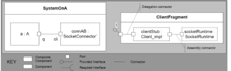
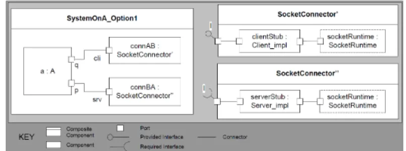
The first option is to keep a modified variant of the composite that only contains the subset of parts which are deployed on a certain node. Fig. 14.6 shows the result for the uni-directional variant of the example: SocketConnector’ is the variant of the original SocketConnector. It contains the subset of parts that are allocated on NodeA, clientStub and socketRuntime. Note that splitting is in general not trivial, since the split must also consider super-classes. In our case, the ports of the socket are inherited by an abstract interaction component (aka connector type). Depending on how the super-class is organized, the composite only inherits from a subset of super-classes or super-classes need to be split as well which complicates the design.
Fig. 14.6 Option 1: Splitting components in the uni-directional example given in Fig. 14.1 by keeping composites.
Please note that it is not the part that is allocated on a certain node, but the (sub-) instance that is associated with a part. If there is a second instance whose sub-instances are allocated in a di↵erent way, a second variant of the composite with a part subset must be created. This is shown in Fig.
14.7. The creation of multiple variants implies a certain overhead which –although small– may be non-acceptable on resource constraints systems.
Fig. 14.7 Option 1: Splitting components in the bi-directional example given in Fig. 14.5 by keeping composites.
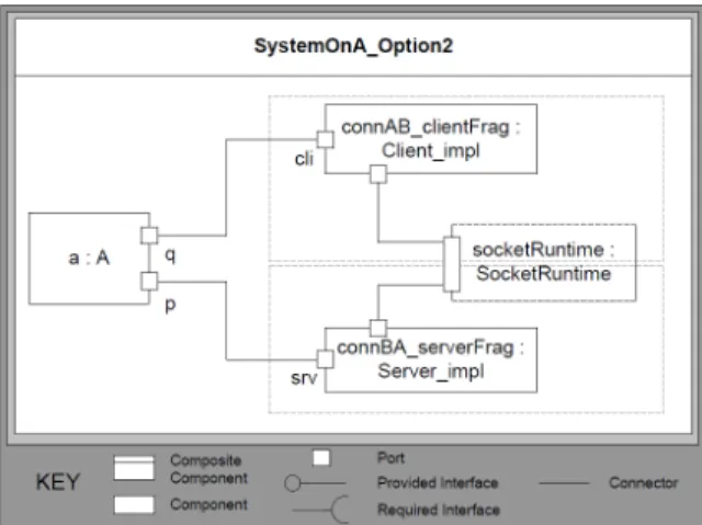
Option 2 – Flatten composite
Flattening a composite component is a well-known approach in the literature [6, 7, 11] in which a composite component may disappear in the deployment model, i.e. it is replaced by its internal structure. The internal assembly connections of a composite become assembly connections of the containing composite (the System class in case of the example). The delegation connections2refine
the final targets of existing assembly connections in the containing composite.
Fig. 14.8 shows the example system for NodeA, in which the SocketConnector composite component has been flattened. The two parts in the system typed by a socket implementation have been replaced by parts that are directly typed with elements of the socket implementation. The original composition hierarchy may still be visible via a suitable naming convention for these new parts by prefixing them with the original part name, as done in the example with the prefixes connABand connBA.
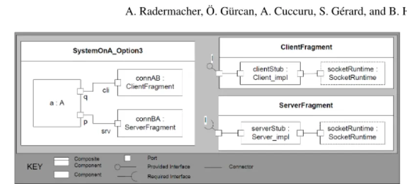
Option 3 – Flatten composite, require explicit fragment sub-components
The third option is a variation of the second solution. We also flatten the SocketConnector composite component, but require that the composite must contain exclusively specific sub-components that we call fragments. A fragment encapsulates the parts of a composite that are allocated on the same node, conversely each fragment within a composite is typically allocated on a di↵erent node. The latter implies a restriction that is verified by a validation rule: fragments may not be connected by UML assembly connectors. The modeling of SocketConnector with fragments is shown in Fig. 14.9.
The resulting system is shown in Fig. 14.10. The composite has been flattened; the fragments have become top-level elements. The result looks very similar as the solution in Fig. 14.7, e↵ectively the explicitly modeled fragments replace the derived subsets of the composite.
2Assembly connectors are connections between inner parts, delegation connectors connections
Fig. 14.8 Option 2: Splitting components in the bi-directional example given in Fig. 14.5 by flattening composites.
Fig. 14.9 Option 3: The SocketConnector composite component with explicit fragments.
14.4 Support for splitting composites in existing frameworks
In the following, we sketch the existing component frameworks that have a specific support for interaction components3and show how these frameworks may handle composite splitting, mainlyin the context of interaction components.
3Having specific support for interaction components is needed in order to be able to address the
Fig. 14.10 Option 3: Splitting components in the bi-directional example given in Fig. 14.5 by flattening the System composite with explicit fragments.
14.4.1 DDS for CCM
The connector element that we have used in the motivating example is supported in multiple compo-nent models. As already mentioned, it has been standardized within the context of the OMG (Object Management Group) standard CCM (CORBA component model) [13]. More specifically, it is part of the DDS for CCM [15] specification, enabling component interactions via OMG’s Data Distribu-tion Service. Within this specificaDistribu-tion, the term GIS (Generic InteracDistribu-tion Support) is introduced. GIS will be part of the upcoming OMG unified component model [17]. The underlying connector extension for CCM has been proposed in [19]. Deployment with CCM is based on the specification for Deployment and Configuration (D&C) of distributed component-based applications [14]. The D&C standard describes a so-called deployment plan, a specification of instances that refer to component implementations, the interconnections between these instances, their configuration and their allocation to a node.
In the DDS for CCM specification, DDS interaction components are not identified as composites, since there are separate writer and consumer components. This is useful in case of DDS in which connections are implicitly created by sharing the same topic, i.e. there is no single component that represents an interaction. But the generic interaction support enables explicit point-to-point interactions for which composites would be useful. D&C supports two kinds of implementations of software components [14]:
• Monolithic implementations, where the code of the composite component is compiled as a single block.
• Assembly (composite) implementations, including the set of implementation of all the parts that the composite component includes. There must eventually be monolithic implementations at the “leaves” of the hierarchical implementation. Assembly allows dependent packages to be deployed on distinct target nodes, enabling flexibility in composite component instantiation. While the D&C specification allows composites, the composites have no identity and cannot be reused. This has been analyzed in [10]. In this article, the authors review and compare the ability of 13 component models of handling component composition. They identify the development with D&C as a “deposit only” repository for composites: a composite component that results from the component assembly step can be deposited in a repository but cannot be retrieved from it, because it does not have an identity of its own. In the end, only monolithic components are deployed, i.e. the component hierarchy is flattened. Note that this does not only apply to interaction components but to all composite components, even if they deployed on the same node, i.e. a stronger variant of the flatten option in section 14.3.
shown in Section 14.2.
14.4.3 SOFA
In SOFA5[1, 3, 12], connectors are used to support transparent distribution of applications. A
connector might support a transport mechanism such as CORBA6or low-level socket mechanisms.
In this context, they are responsible for marshalling and unmarshalling and interfacing with the transport layer. But they can also be used for synchronization or interception. Connectors are automatically generated.
In SOFA, the connector plugging is performed after component instantiation using a split of the connector into two parts: the server and the client connector units (fragments). Whenever component interfaces query a connector reference, the corresponding server connector unit is returned (instead of returning a reference directly to an interface). Similarly, whenever an interface is being connected to another component, a client connector unit is created and bound. The connector composite specifies the parts, into which it is later split explicitly, corresponding to the fragment option (Option 3).
14.4.4 Qompass
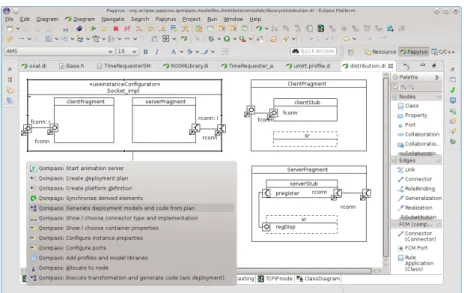
The FCM [8] (Flex-eWare component model) component model has the objective to unify the component models of Fractal and CCM. It extends the UML composite structures with dedicated interaction components – as, for instance, the socket connector presented in the motivating example (Section 14.2) – flexible ports and container services. This component model is supported by an add-on to the Papyrus7UML modeler called Qompass designer. Fig. 14.11 shows the definition
of the socket interaction component within a Qompass modeling library and the Qompass context menu. This add-on was first introduced as eC3M (embedded Component Container Connector Model/Middleware) [18]. Upon deployment, the tool chain executes a model transformation that replaces annotated UML connectors with the associated interaction components, as shown in the motivating example given in Section 14.2 (the transition from Fig. 14.1 to Fig. 14.2). This transformation includes an instantiation of the interaction component to the context in which it is used (similar to the generation of in SOFA). A further model transformation produces a model per
4 The Fractal Component Model, http://fractal.objectweb.org/specification/, last access on
07/02/2014.
5SOFA 2, http://sofa.ow2.org/, last access on 07/02/2014.
6Common Object Request Broker Architecture, http://www.corba.org/, last access on 07/02/2014. 7The Papyrus UML modeler – http://www.eclipse.org/papyrus, last access on 23.01.2014
node. During the latter, the composites within the FCM models are split. The composites that are concerned are mainly interaction components and the dedicated system component.
Fig. 14.11 Definition of a socket connector within Papyrus, using the client and server fragments
In Qompass, interaction components with explicitly identified fragments are flattened, i.e. the fragment option (Option 3). Being based on UML, Qompass must handle the specific case of a dedicated system component. Such a component is required, since connections can only be defined in the context of an enclosing composite (unlike for instance in D&C). Thus, Qompass must also split the system component, if the contained components are deployed on di↵erent nodes. The approach that has been chosen is to create a specific variant of the System component on each node, i.e. the keep option (Option 1). Note that it is not possible to flatten the system component, since the UML component model requires an enclosing composite for defining connections.
14.5 Discussion
Obviously, all splitting options increase the number of classes. When the composites are kept (Option 1), there is no need to remove additional assembly connections from the system. Flattening (Option 2) makes top-level composites bigger, since these composites have to incorporate the contents of a flattened component (sub-components and their connections) instead of the component itself. In fragmentation (Option 3), a possible split is anticipated and explicitly defined by the developer. Since the composite may not have assembly connectors, no additional connectors are added to the Systemclass (the composite that contains the split composite). Based on this observation, to make a quantitative comparison, we measured the footprints associated with the di↵erent splitting options. The code size of a complete application has been measured in case of the simple uni-directional system and its bi-directional variant for splitting options 1, 2 and 3, as shown in Table 14.5. The
Simple uni-direct
13904
12233
13936
Simple bi-direct
14668
13754
14710
However, flattening is evidently not possible for a top-level component, since the transformation towards a model having only monolithic components and assembly connections8is rather straight
forward. Thus, the resulting system is di↵erent, since the internal connections become visible in the system. This may be annoying, if the same composite is instantiated more than once in the original model, e.g., if we have more than one socket connector. Also note that the internal structure of an interaction component might be more complex than the simplified SocketConnector used for illustration purposes. This makes it a bit difficult to link it with the original model, for instance when debugging is done on the level of the deployed model, but fixes must be made in the original design model. Other tasks that are a↵ected by this di↵erence are for instance trace mechanisms (which must translate a trace specification for a composite into suitable specifications for the inner parts) and the replacement of a composite implementation with another one (e.g. in the context of di↵erent system configurations). The advantage is a slightly reduced footprint and a resolution for the splitting problem.
Another important thing to consider is debugging. Debugging is generally defined as the process of locating and fixing or bypassing bugs in the underlying software, to achieve reliable systems. To this end, various debugging tools are developed help to identify errors at the various stages of the software development process. Especially, debugging and visualizing the behavior of component-based embedded software using models such as the Unified Modeling Language (UML) [16] diagrams has become a reality. For instance, model-based tools such as Papyrus and the commercial tool Rhapsody9(“live-animation” features) enable model-based debugging of embedded software
systems using sequence diagrams and state charts. In case of Papyrus, animation is based on an injected probe that communicates with the development environment. Showing the activation of a delegation connector within a composite is evidently only possible, if the composition hierarchy has not been flattened. Hence, the closer the deployed model is to the original architecture, the easier it is to debug. In this sense, since keeping the original composition hierarchy (Option 1) has the advantage that the deployed model is closer to the original architecture, it is a bit easier to debug compared to Option 2 and 3.
Besides, in some domains (such as aerospace and electrical cars) the overall architecture of vehicles becomes very complex [20]. One possibility to tackle this complexity at run-time, is the use of dynamic reconfiguration abilities. Dynamic reconfiguration is a process of modifying the software architecture and enact the modifications during the system’s execution [9], which means making the software evolve from one configuration to another at run-time, as opposed to design-time, while introducing little or ideally no impact on the systems execution. This prevents the system to be taken
8In UML-like languages, connectors are always owned by a composite, i.e. a System composite
must be kept.
9IBM Rational Rhapsody Developer, http://www-03.ibm.com/software/products/en/ratirhap/, last
o↵-line and/or restarted to accommodate changes. Considering the split of composite components discussed in this chapter, a dynamic reconfiguration would replace the SocketConnector component with another interaction component. In order to be able to do this seamlessly, splitting Option 1 is better suited since we do not need to remove additional assembly connections from the system.
14.6 Conclusion
We have shown that the deployment of composite instances which are partly allocated on one node and partly on another can be tackled in several ways with di↵erent advantages and disadvantages. The choice of a suitable split option depends on properties of the composite that should be split. For instance, in Qompass designer we keep the composite of the System component, since this particular component (no inheritance, single instance) can be split easily and since flattening would result in multiple top-level components. On the other hand, we flatten interaction components and require the explicit use of fragments, since we want to avoid the problems that come with multiple instances (creating potentially multiple variants of a split component). The choice depends also on the deployment goals, e.g. whether an optimized application compared to a debug-enabled application should be delivered. The options are rather evident, but –to our knowledge– the task had not been examined systematically earlier.
The interest of deploying composites with complex allocation properties is not artificial: a composite definition is a suitable choice for interaction components enabling distribution. In this context, the raised issues concern principally framework and tool developers, i.e. developers of interaction components and developers of model transformations associated with the split of composites. However, the results also apply to a sub-system modeled by composite classes that need to be allocated on multiple execution nodes. In this case, system modellers or designers are concerned since they need to respect restrictions associated with the split of a composite and should know the consequences of di↵erent split options.
References
[1] Bálek D (2002) Connectors in software architectures. PhD thesis, Charles University Prague, Faculty of Mathematics and Physics; Department of Software Engineering
[2] Bruneton E, Coupaye T, Leclercq M, Quéma V, Stefani JB (2006) The fractal component model and its support in java: Experiences with auto-adaptive and reconfigurable systems. Softw Pract Exper 36(11-12):1257–1284, DOI 10.1002/spe.v36:11/12, URL http://dx.doi.org/ 10.1002/spe.v36:11/12
[3] Bureš T, Plasil F (2004) Communication style driven connector configurations. In: Lecture Notes in Computer Science, vol 3026, p 102–116
[4] Clements P (1996) A survey of architecture description languages. In: Software Specification and Design, 1996., Proceedings of the 8th International Workshop on, pp 16–25, DOI 10.1109/IWSSD.1996.501143
[5] Coupaye T, Stefani JB (2007) Fractal component-based software engineering. In: Südholt M, Consel C (eds) Object-Oriented Technology. ECOOP 2006 Workshop Reader, Lecture Notes in Computer Science, vol 4379, Springer Berlin Heidelberg, pp 117–129, DOI 10.1007/ 978-3-540-71774-4_13, URL http://dx.doi.org/10.1007/978-3-540-71774-4_13 [6] Feher P, Meszaros T, Lengyel L, Mosterman P (2013) A novel algorithm for flattening
virtual subsystems in simulink models. In: System Science and Engineering (ICSSE), 2013 International Conference on, pp 369–375, DOI 10.1109/ICSSE.2013.6614693
33(10):709–724
[11] Leveque T, Carlson J, Sentilles S, Borde E (2011) Flexible semantic-preserving flattening of hierarchical component models. In: Software Engineering and Advanced Applications (SEAA), 2011 37th EUROMICRO Conference on, pp 31–38, DOI 10.1109/SEAA.2011.15 [12] Malohlava M, Hnetynka P, Bures T (2013) {SOFA} 2 component framework and its
ecosystem. Electronic Notes in Theoretical Computer Science 295(0):101 – 106, DOI http://dx.doi.org/10.1016/j.entcs.2013.04.009, URL http://www.sciencedirect.com/science/ article/pii/S1571066113000315, proceedings the 9th International Workshop on Formal Engineering approaches to Software Components and Architectures (FESCA)
[13] OMG (2006) CORBA Component Model Specification, Version 4.0. OMG Document formal/2006-04-01
[14] OMG (2006) Deployment and Configuration of Component Based Distributed Applications, v4.0. OMG document formal/2006-04-02
[15] OMG (2011) DDS for Lightweight CCM, v1.1. OMG document ptc/2011-01-14
[16] OMG (2011) Unified Modeling Language: Superstructure, Version 2.4.1. OMG Document formal/2011-08-06
[17] OMG (2013) Unified Component Model for Distributed, Real-Time and Embedded Systems, Request For Proposal Draft. OMG document mars/13-05-03
[18] Radermacher A, Cuccuru A, Gerard S, Terrier F (2009) Generating Execution Infrastructures for Component-oriented Specifications With a Model Driven Toolchain – A case study for MARTE’s GCM and real-time annotation. In: Eighth International Conference on Generative Programming and Component Engineering (GPCE’09), ACM press, pp 127–136
[19] Robert S, Radermacher A, Seignole V, Gérard S, Watine V, Terrier F (2005) Enhancing Interaction Support in the CORBA Component Model. In: Rettberg A, Zanella MC, Rammig FJ (eds) From Specification to Embedded Systems Application, Springer, IFIP TC10 Working Conference: International Embedded Systems Symposium (IESS)
[20] Venkatesh Prasad K, Broy M, Krueger I (2010) Scanning advances in aerospace & automobile software technology. Proceedings of the IEEE 98(4):510–514, DOI 10.1109/JPROC.2010. 2041835