Publisher’s version / Version de l'éditeur:
Vous avez des questions? Nous pouvons vous aider. Pour communiquer directement avec un auteur, consultez la première page de la revue dans laquelle son article a été publié afin de trouver ses coordonnées. Si vous n’arrivez pas à les repérer, communiquez avec nous à PublicationsArchive-ArchivesPublications@nrc-cnrc.gc.ca.
Questions? Contact the NRC Publications Archive team at
PublicationsArchive-ArchivesPublications@nrc-cnrc.gc.ca. If you wish to email the authors directly, please see the first page of the publication for their contact information.
https://publications-cnrc.canada.ca/fra/droits
L’accès à ce site Web et l’utilisation de son contenu sont assujettis aux conditions présentées dans le site LISEZ CES CONDITIONS ATTENTIVEMENT AVANT D’UTILISER CE SITE WEB.
Building Research Note, 1985-04
READ THESE TERMS AND CONDITIONS CAREFULLY BEFORE USING THIS WEBSITE.
https://nrc-publications.canada.ca/eng/copyright
NRC Publications Archive Record / Notice des Archives des publications du CNRC :
https://nrc-publications.canada.ca/eng/view/object/?id=e9aafda0-ca3d-4f47-adaf-5c7e2a19abb3 https://publications-cnrc.canada.ca/fra/voir/objet/?id=e9aafda0-ca3d-4f47-adaf-5c7e2a19abb3
NRC Publications Archive
Archives des publications du CNRC
This publication could be one of several versions: author’s original, accepted manuscript or the publisher’s version. / La version de cette publication peut être l’une des suivantes : la version prépublication de l’auteur, la version acceptée du manuscrit ou la version de l’éditeur.
For the publisher’s version, please access the DOI link below./ Pour consulter la version de l’éditeur, utilisez le lien DOI ci-dessous.
https://doi.org/10.4224/40000488
Access and use of this website and the material on it are subject to the Terms and Conditions set forth at
A test method to determine air flow resistance of exterior membranes
and sheathings
I
--
s d
'I
THI. 1392no. 227
C*2
BUILDING
RESEARCH
NOTE
h TEST nBTBOD
TO
PBTEWXNEAIB FLOW
w
~ ~ B L - I U T W $ Q U ]
% Rpmbcrg
and
H.Ka 'truaaf i n1
ANAL1
--
f
P t d g i u n
of
WildirtgResearela,
h
.ionmlEeaearch
@ouncTlof
Canada'Ottawa,
Ayril
1985I
NATIONAL RESEARCH COUNCIL OF CAHADA D I V I S I O N OF BUILDING RESEARCH
A TEST METHOD M DETEKMINE AIR FLOW RESISTANCE OF EXTERIOR MEPIBWES AND SHEATHINGS
by
M. Bomberg and M.K. Kumaran
O t t a w a ,
T h i s n o t e describes a test method for determination of air flow resistance of exterior mmhranes and sheathinge, The t e s t specimen is
p l a c e d between t w o chambers with d i f f e r e n t a i r pressures and the volumetric
a i r flow rate through it at a steady s t a t e is determined. The relevant experimental q u a n t i t i e s can presently be measured with precision better than
0 . 5 % and with an accuracy of 2 t o 3%, using commercial instruments. However, the instrumental precision does not mean much, due to the
uncertainty introduced by material variability normally occurring in
cornntercial products. This aspect of the test method is studied and a practical rest procedure is suggested.
The objective of t h i s study was to develop t e s t methods a p p l i c a b l e to
breather type membranes and exterior sheathing, for consideration by
Canadian General Standards Board (CGSB). Moisture control committee af
CGSB, responsible for t h i s standard [CAN2-51-32-H77), d e c i d e d that f o r
adequate material characterization, in addition t o the water vapour
transmission t e s t , a i r permeability and water penetration resistance tests
should a l s o be performed.
S i n c e there are no ASTM t e s t methods a v a i l a b l e f o r t h i s purpose,
Material Evaluation Department of Canada Mortgage and Housing Corporation requested that t h e Dfvision of Building Research develop a new test method
for determination of a i r flow resistance of exterior membranes. The CGSB Committee will review the proposed test method and recommend the c r i t e r i a
for material acceptance.
The relevant experimental quantities t o be determined in the t e s t
method are a volumetric rate of air f l o w and a corresponding pressure
difference. These two quantities can p r e s e n t l y be measured w i t h a p r e c i s t o n better than 0.5% and with an accuracy of 2 t o 3X, using commercial
instruments. However t h i s precision and accuracy w i l l n o t mean much, due to the uncertainty introduced by material variability in camercial products. This aspect af the t e s t method is studied and a p r a c t i c a l t e s t procedure is
suggested.
A unidirectional steady laminar flow of a i r through a porous membrane
of thickness e, from a region of pressure p l , to one of pressure p p is represented in Figure I. From Darcg's l a w 1
Q = vaiumetr5c f l o w rate of air,
A = n o d cross-sectional area of the membrane, tt = f n t r i n s l e a i r permeability ~f t h e membrane, q = dynamfc v i s c o s i t y of air,
AP = difference in "piezomtric pressurew of a i r across t h e membt ane
.
If the air pressure p l is not significantly larger than atmospheric pressure p2 (and hence the difference p i
-
p2 is not large) far all practical purposesand equation (1) hecomes
where: Ap = p l - p 2 .
Equation ( 3 ) is applicable to homogeneous materfals and membranes.
However, e x t e r i o r membranes and sheathings are non-hamageneous
.
For practical application, therefore, it is useful t o define the a i r f l o w resistance2 (R) of the specimen asFrom equations (3) and € 4 )
Thus from an experimental setup compatible w i t h that s h m in Figure 1, measurements of Q , Ap and A may be used t o evaluate R. The air flow
resistance determined w i l l be an average property of the membrane f o r the metering area and so the membrane need not be homogeneous or of uniform
thickness. The analogy b e t w e e n air flow resistance, as defined here, and
apparent thermal resistance of a thermal insulation is obvious.
INSTRUMENTS
The experimental s e t u p f o r the determination of a i r flow resistance is shown in Figure 2. The chambers A and
B
are made of plexiglas cylinders.The test specimen I s placed between these chambers to separate them and h e l d air tlgh't with the help of an ' 0 ' ring (Figure 3) ; f urrher, the assembly is held together by a pressure jack. Compressed dry a i r from a regulating
v a l v e is admitted to the upper container. This air flows through the porous
specimen i n t o the lower compartment, which is open to the atmosphere. Consequently an a p p r o p r i a t e steady s t a t e is maintained in the assembly.
Different ~ t e a d y states can be achieved by changing the air pressure i n the
The steady state f l o w rate (Q) in equation ( 5 ) is measured by flow meters connected between the regulating valve and the upper chamber
(Figure 2).
Three
different f l o w meters were used during the course of this study :1) model 8141 manufactured by Hatheson, with a measuring range of 0 to
5 cm omin- 1
,
2) model 600 manufactured by Matheson, with a masurfng range of 0 to
150 c m 3 - d n l ,
3 ) model EM4333 manufactured by Union Carbide, with a measuring range of 20
to 900 ~rn~.min-~.
These f l o w meters w e r e calibrated according to the soap bubble w t h o d
commonly used in chromatography. A Hastings m i n i - f l o w calibrator (model
HBM-1A) was used f o r this purpose. The accuracy of this equipment is
estimated t a be 0.25%.
Mr pressure difference across t h e specimen was measured by using either
a) Wlidyne d i f f e r e n t i a l pressure transducer with model CDC 23 demodulator
and a measuring range of 0 t o 100 Pa, or
b) micromanometer MPGKDF manufactured by Air Instruments Resources Ltd.
(Chalgrove, Oxford,
UK),
with measuring ranges of 0 t o 0 . 5 , O to 2, 0 to5 and 0 to 6 kPa.
These instruments were checked by comparing w i t h a " h e r Water
Manometer" calibrated at the Division of Physics, NRC. The accuracy depended on t h e absolute value of the pressure, For example, from 20 to
500 Pa, the estimated inaccuracy fell from 6 t o 2.4%. For the pressure
range used i n t h i s test method, the accuracy of the Instruments is w i t h i n 2
to 4 % .
!Hw metering area A in equation ( 5 ) is defined by t h e ' 0 ' ring. Under
the clamping pressure of abolre 10 kPa, compression of the. Wring reduces the
metering area t o 143.6 cm2. Thus A = 143.6
*
0.3 cm2 has been used.According t o equation ( 3 ) one measurement under steady s t a t e condition 3s s u f f i c i e n t to determine the ratio (dp/Q). However this ratio could be
more precisely determined by measuring Ap as a function of Q and by a
subsequent least-squares analysis. PRECISION OF THE TEST MEmOD
The precision of the test method was estimated by studying the a i r flow resistance of grade 1 and grade
4
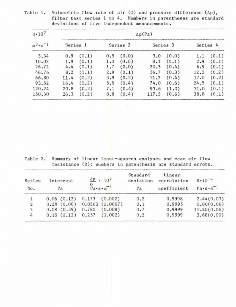
quantitative f i l t e r papers, as follow^.One specimen of grade 1 filter paper w a s used first t o check the precision
wZth wMch Q and A p are measurable. Efght flow rates from 3.34 t o
150.3 m 3 , 8 - l were chosen arbitrarily, These flows were reproducible w i t h a precision better than 0.25%. In a series of measurements these flows were
reproduced five times and each t i m e t h e corresponding pressure differences
were measured. The average deviation of these pressure measureents w a s
0.05 Pa and the pressure differences measured were between 0.9 and 26.3 Pa.
Four other serles of measurements were done under the assumption that
these f i l t e r papers are i d e a l l y homogeneous materials.
In
the second series, five different gradeI
papers w e r e used and in' the t h i r d series, five different grade4
papers.In
the fourth series, f i v e gradeI
papers were stacked together In f i v e d i f f e r e n t orders and each resultant stack wass t u d i e d as a separate membrane. The f i f t h series was a r e p e t i t i o n of series three with five grade 4 p a p e r s put together. The results are summarized in Table 1
and
the l i n e a r dependence of Ap on9
is shownIn
Figures4
and 5.Results of the linear least-squares analyses are given in T a b l e . 2 . The values of the intercept and the slope were found for each series of
measurements. In p r i n c i p l e , the intercept should always be equal t o zero. In practice, the residual values for the intercept, shown in Table 2, are a measure of experimental imprecision. The influence of this imprecision on
t h e calculated R-value for flow rates higher than 20 cm3-min-I is
negligible. The slope (ApiQ) in equation ( 5 ) is determfned
In
each case with a standard error <l.lX and t h i s is a measure of the overall. p r e c i s i o n attainable from t h i s t e s t method.PILOT STUDY ON SELECTED COMMERCIAL PRODUCTS
The precision quoted above I s valid for.ideaX materials with uniform
pore s t z e and distrfbution, l i k e the filter papers used in the serles. For
real
materials t h i s ideal s i t u a t i o n is seldom realized. Bence, the following p i l o t study was undertaken t o formulate a test procedure for commercial products. Tea rolls of breather membranes or papers were selected from products delivered by various Canadian manufacturers.Specimens were taken from random l q c a t i a n s on each roll and each specimen w a s d e s i g n a t e d with
a
roll number and a specimen number. The differentsamples chosen included membranes guch as asphalt-saturated felt (both plain and perforated), saturated buPlrl5ng paper and breather type sheathing and
p l a s t i c mmbranee.
Frqm each roll four specimens
were
studied. The results are summarized in Table 3, along w i t h an appraprtate atatisticdl analysis. The t e s t method when a p p l i e d t o nearly ideal membranes like f i l t e r papers a l l o w s adetermination of air flaw resistance with a variation of 2 to 4 4 . At the
same time, as seen from Table 3 , similar t e s t s on comnercfal membranes can
result in a variation of 50 to 100%. This large v a r i a t i o n
i s
attributableto material inhomogeneity. Rowever it may be important to look at t h i s variabflity in term of the size of the rsetering area and the umber
of
specimens tested.
The s i z e of the metering area indeed influences the air flow
resistance, as 1s demonstrated from the following measurements with a Gurley densometer on membranes 7 and 10. The densometer measures the time taken by 100 em3 of air at a pressure of 1.2 kPa t o flow through a 5 em2 area of the membrane. Various measurement# on membrane 10 recorded times between 26 and
75 s and oa membrane
7,
between 8aad 3Q6
a. Thus 5 cm2 is far too smalla
metering area far materials with l a ~ g e spatial variability, The area choaen f o r the t e s t method described here is approximately 30 times larger than the metering area
In
the densometer; it will reduce the variability of theresults considerably. This metering area is also five times larger than the minimum requ5red in the similar t e s t for water vapour transmission,
Since material non-unfformity introduces large variability in the t e s t r e s u l t s , one way to overcome t h i s is Lo increase t h e number of specimens
studged. However, f o x practical and economic reasons this number w i l l have to be kept r e l a t i v e l y small. Results obtained by studying five specimens f r o m each sample may reduce t h e v a r i a b i l i t y to an acceptable level.
APPLICATION
OF
THE TEST METHODThe t e s t method described above w a s used to d e t e r d n e air flaw
resistances of f i f t e e n different membranes; t h e s e i n c l u d e d the t e n samples used for the pilot study and five a d d l ~ i o n a l samples.
The following test procedure w a s s p e c i f i e d :
1) f i v e s p e c h e n s . t o b e tested and the average
of
f i v e r e s u l t s reported as air flow r e s i s t a n c e of the material;2) at l e a s t four data p a i r s to be used to calculate the air flow
res is t ance ;
3 ) as appropriate for any specimen, pressure d i f f e r e n c e s ranging between 1
and 1200 Pa and a i r flow rates ranging between 20 and 900 cm3-inin-' to be used.
The results of these s t u d i e s are summarized i n Table 4. By increasing
the number of specimens from four in the p i l o t studies to f i v e , the width of
a confidence interval calculated on a 9% p r o b a b i l i t y level is significantly reduced ( e . g . from 97% to 57%). The uncertainties are S t i l l relatively high, but the average values o f the airflow resistances l i s t e d in Table 4
arc acceptable for material characterization and practical calculations-
The t e s t method for determination of a i r flow resistance may be applied
to membrane3 or t o sheathing materials. In the latter case two additional requirements should be s p e c i f i e d : (I) maximum thickness of the specimen,
and (2) sealing of the edges. Specimen thickness w i l l be l i m i t e d to 32 nun, similar t o the requirements of the ASTM E96-80 ~ t a n d a r d . ~ The seal of paraffin wax on the specimen edges may also be used ( s e e Figure 6 ) . A
simpler procedure, a p p l i c a b l e f o r homogeneous materials with low air f l o w resistance, consists of testing larger specimens so that the metering area is enclosed by a collar 3 t o 5 cm wide, which provides s u f f i c i e n t resistance
t o the lateral flow of air.
I n summary, the proposed test method was suitable for t e s t i n g both
membranes and boards. The objectives formulated f o r t h i s project have been achieved by the development of the t e s t method. C o l l e c t i n g data on
different materials is beyond the scope of the t e s t method development.
However, in engineering applications a new test method may only be accepted
when its applicability is proven with respect to materials of known
performance. To generate some comparative data, a f e w a i r barriers and exterior sheathing materials were tested. The results are summarized in
1. D u l l i e n , P.A.L. Poraus Media
-
F l u i d Transport and Pore Structure, Academfc Press, Hew York, p. 79, 1979,2. Standard T e s t Method f o r Air£ low Resistance of &oustical MaterZals, Annual Book of ASTM Standards Part 18,
ASTM
C522, p. 262-267,1981.
3 . Standard T e s t Method for Water V a p ~ r Transmission of Materials, Annual
T a b l e 1. Volumetric flow rate of a i r
(0)
and pressure differenceCAP),
f i l t e r t e s t series 1 to 4 . Numbers in parentheses are standarddeviations of f i v e independent measurements.
*3.,-1 Series I Series 2 Seri.es 3 Series 4
Table 2, Summary of l i n e a r least-squares analyses and mean a i r f l o w
resistance (R); numbers in parenthesis are standard errors. St aadard Lf near
Series Intercept
4 . ~ .
+ 107 deviation correlationR - ~ O - ~
Table 3. A i r E l m resistance (R) of commercial membranes, as determined during pilot study. Confidence interval refers to 95% probability l e v e l .
- - -
R- 1
oW4
Confidence interval-1
Pa-s-m
R ~ l l *dR
No. Spec. 1 S p e c . 2 Spec. 3 Spec.
4
Average pa 0s om-1 percent-
T a b l e 4. Air f l o w resistance (R) of membranes. Confidence i n t e r v a l refers t o a 95% probability l e v e l . R- pa s 011-1 Confidence Membrane Me an interval
Table 5. A l r flaw resistan~e nf selected air barriers and exterior sheathing materials, Average R ~ams-m-1 Range pa* s -m-1 0.15 mm ( 6 m i l ) polyethylene no measurable
air
flow-
0.05 ram ( 2 m i l ) polyethylene 0.15 m ( 6 m i l ) polyethylene
with one pfnhole (0.8 mm) 25 mm thick pblystyrene
12 mm thick insulatf ng
fibreboard sheathing
P O R O P L U G F I G U R E I
I
U N I D I R E C T I O N A L L A M I N A R FLOWO F
AIR
T H R O U G H A P O R O U S MEMBRANEL
COMPRESSED A I R2
REGULATOR 3 FLOW METER 4 MANOMETER5 TEST CHAMBERS A AND 3
6 MEMBRAME UNDER TEST
F I G U R E 2
E X P E R I M E N T A L SET-U.P FOR D E T E R M l N A T l U N
OF
A I R FLOW R E S I S T A N C ED E T A I L A F I G U R E 3 T € S T C H A M B E R W I T H A MEMBRANE UNDER T E S T . C L A M P S W I T H P R E S S U R E
10
k P a C O M P R E S S O - R I N G 0 . 3 rnm, C H A N G I N G THE DIAMETER O F THE S P E C I M E N F R O M1 3 6 . 6
TO 1 3 5 . 2 m m . METERING A R E AOF
1 4 3 . 6 k 0 . 3crn2
I S U S E D F O R C A L C U L A T I O N SL I N E A R DEPENDENCE OF P R E S S U R E D I F F E R E N C E dp ON R A T E Q O F A I R F L O W FOR P R E C I S I O N T E S T S O N F I L T E R P A P E R
I
1
I
-
-
- - --
- - S E R I E S 2 - m --I
F I G U R E 5 L I N E A R DEPENDENCE OF P R E S S U R E D I F F E R E N C E A p O N R A T E Q O F A I R FLOW F O RP R E C I S I O N
T E S T S O N F I L T E R P A P E RA I R SPECIMEN WAX-SEALED INFRAME