Publisher’s version / Version de l'éditeur:
Vous avez des questions? Nous pouvons vous aider. Pour communiquer directement avec un auteur, consultez la première page de la revue dans laquelle son article a été publié afin de trouver ses coordonnées. Si vous n’arrivez pas à les repérer, communiquez avec nous à [email protected].
Questions? Contact the NRC Publications Archive team at
[email protected]. If you wish to email the authors directly, please see the first page of the publication for their contact information.
https://publications-cnrc.canada.ca/fra/droits
L’accès à ce site Web et l’utilisation de son contenu sont assujettis aux conditions présentées dans le site
LISEZ CES CONDITIONS ATTENTIVEMENT AVANT D’UTILISER CE SITE WEB.
ASHRAE 1981 Fundamentals Handbook, p. 32, 1981
READ THESE TERMS AND CONDITIONS CAREFULLY BEFORE USING THIS WEBSITE.
https://nrc-publications.canada.ca/eng/copyright
NRC Publications Archive Record / Notice des Archives des publications du CNRC :
https://nrc-publications.canada.ca/eng/view/object/?id=ac7b149a-8dc8-40f6-896c-3c1e39bb6076
https://publications-cnrc.canada.ca/fra/voir/objet/?id=ac7b149a-8dc8-40f6-896c-3c1e39bb6076
NRC Publications Archive
Archives des publications du CNRC
Access and use of this website and the material on it are subject to the Terms and Conditions set forth at
Ser
TH1
N21d
a.
1235
C .
2
National Research
Conseil national
3LDG
I
Council Canada
de recherches Canada
DESIGN HEAT TRANSMISSION COEFFICIENTS
Chapter 23, ASHRAE 1981 Fundamentals Handbook
AN
ALYZEP
Reprinted with permission
DBR Paper No. 1235
Division of Building Research
Price
$3.00
OTTAWA
NRCC 23748
CHAPTER
23
DESIGN HEAT TRANSMISSION COEFFICIENTS
Heat Transfer Definitions andSymbols; Surface Conductance; Calculatin~ Overcrll CoeU1cients;Alternate Method of~ a l c u l ~ i o n ; overall ~ o d f i f i e n t s and Their ~ r a c t i c a l Ure; Insulating
~onsrmcrions~~djuslmenlfor
~raming; Curtain Walls; Ventilated Anics; Foundarion Coefficients; Class andDoor Coefficients; EsrimatedHeatLoss Due to Injltration; Calculating Surface &peratures: Conductiviry ofidustrial insu/at~ons; Bare Surface Heat Losses; Heat Flow Calnrlationr; Buried Pipe Lines; Thermal
Chamcteristics andResponse Factors for F i o o r
all^,
andRoof3T
HE
design of a heating, refrigerating, or air-conditioning system, including selection of building insulation, sizing of piping and ducts, or evaluation of thermal performance of system parts is based on the principles of heat transfer given in Chapter2.
The equations most widely used to estimate heat transfer loads chargeable to the various parts will usually determlne the heat transfer rate under steady state conditions. Forr
piven part under standard conditions, this rate is a speclflc value,U,
the overall codficient of heat transmission or thermal trmsmlttmnce,This ahapter
11
concerned with the concepts and procedures for dstermlnlng luch co~fficisnts, and includes a brief discussionof
frctora that may affect the values of these coefflclenta and performanceof
thermal insulations. Coefflcientsmay
be
determlncd by testing, or computed from known values of thermal conductance of the various com- ponents. Procedures for calculrtlnp coefficients are illustrated by examples and, because It Is impracticable to test all combinations of materials, tables of comouted design values-
for themore common constructions are given.Units in this chaoter are in the customary
(i.e..
U.S.. English, and cgs) systems. In the following defiiitibnsof heat transfer. the customary unit, followed by the S1 unit, is given. Note that although theSI
unit of temperature is ihe kelvin (K), the degree Celsius (formerly centigrade) is properly used withSI
units. The temperature interval one degree Celsius equals one kelvin exactly. Factors for converting to SI are given in Table 18 and in Chapter37.
HEAT TRANSFER DEFINITIONS AND
SYMBOLS
q
=
thermal lransmission or rate of heat fiow; the quantity of heat flowing due to all mechanisms in unit time under the conditions prevailing at that time; in Btu/h or W.Note: Mechanisms relate to modes of heat transfer by solid con- duction, mass transfer, gas conduction, ,co"vection, and radiation. These may occur separately or in combtnatton, partially or totally depending upon spectfic circumstances.
k
orA
= thermal conductivity; the thermal transmission, by conduction only, in unit time through unit area of an infinite slab in a direction perpendicular to the surface, when unit difference in temperature is established between the surfaces; in Btu.
in./h.
ft2.
F o r W/m.
K.Note I: A body is considered homogeneous when the above property is found by measurement to be independent of sample dimensions.
Note 2: The property must be identified with a specific mean temperature. Thermal conductivity varies with temperature; and direction and orientation of thermal transmission, since some bodies arenot isotropic with respect to the property.
Note
3:
For many thermal insulation materials, thermal trans-mission occurs by a combination of modes of heat transfer. The Tho preparation of this chapter is assigncd to TC 4.4. Thermal Insulation and Moisture Retarders (Total Thermal Performance Design Criteria).
2
measured property should be referred to as an effective or apparent thermal conductivity for the specific test conditions (sample thickness and orientation, environment, environmental pressure, and tem- oerature difference).
r
or w = thermal resistivity; the reciprocal of thermal conductivity; ft2.
F
.
h/Btu.
in. or m.
K/W.C
-
thermalconductance; the thermal transmission in unit time through unit area ofa
particular body or assembly having defined surfaces, when unit average temperature dif- ference is established between the surfaces; Btu/h ft2.
F o r W/m2.
K.
Note I : The average temperature of a surface is one that adequately approximates that obtained by integrating the temperature over the body.
Note 2: When the two defined surtaces of a mass-type thermal insulation are not of equal areas, as m the case of thermal trans- mission in a radial direction (see Chapter 2, Table
Z),
or are not of uniform se aration (thickness), an appropriate average area and average thiciness must be given.Note 3: When heat transfer is by conduction alone, the average thermal conductivity is the product of the thermal conductance per unit area and the thickness. The average thermal resistivity is the reciprocal of the average thermal conductivity. When conduction is supplemented by any or ail of the other modes of heat transfer, the apparent or effective thermal conductivlly is obtained by multi lying the thermal conductance by the thickness. The apparent or efLtive resistivity is the reciprocal of the apparent or effective thermal conductivity.
Note 4: Where there is air passage through the body, the effective thermai conductance (resistance) must include details of the pressure difference across the body. For a body which is transparent to light, the effective thermal conductance (resistance) may include fenestration, but the optical propetties or shading coefficient of the body must be given.
Note 5: The thermal conductance of some bodies is related to their
Note 6: "Total" and "arerrlfi thermal conductance are often used
as
synonyms for thermal conductance.Note 7: Values of thermai conductance (referred to as con- ductances) and their inverses (resistances) of the more common buildina materials are tabulated later in this chaoter.
-
R
-
thermal reslstance; the reciprocal of thermal con- ductance; ft2.
F.
h/Btu or m2.
K/W.U e
thermal transmittance: the thermal transmission in unit time through unit area of a particular body or assembly, includia its boundary films, divided by the difference be- tween the environmental temperatures on either side of the body or assembly; Btu/h.
ft2.
F o r W/m2.
K.
Note 1: This is often referred to as the overall coe&ient of h a t
rmnrf..,
.."
.--.
.
Note 2: In practice, thc fluid is air. the boundary film is thin, and the average temperature ofthc fluid is that obtained by avcraging ovcr afinilereaion of the fluid near this film. -
h
-
film or surface conductance; the thermal transmission in unit time to or from unit area of a surface in contact with its surroundings for unit difference between the temperatureI
23.2
CHAPTER 23
1981 Fundamentals Handbook
of the surface and the environmental fluid temperature;
ISBtu/h
.
ft2
.
F o f W/m2
.
K. l l l l l l l l l l l l l l INote
1:The surroundings must involve air or other fluids for radia-
tion and convection to take place.
Nole
2:Subscripts
iand
oare often used to denote inside and out-
side surface conductances, respectively.
r =
emittmce; the ratio of the radiant flux emitted by a
specimen to that emitted by a blackbody at the same
temperature.
Note: The combined effect of the surface emittances of boundarv
surfaces of an air soace where the boundaries are assumed
tobk
parallel and of large d~nension*,
arcompared
tothe distance bctu.ccn
them,
is of!enreferrcd to
aseffecrivee~n~~ronce
(0.
Values
fora range
ofair spaces and condit~ons
are tabulated later
in thischapter.
Q
-
surface rq7ectance; the ratio of the radiant flux re-
flected by an opaque surface to that falling upon it; dimen-
sionless.
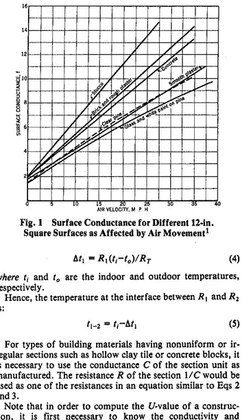
SURFACE CONDUCTANCE
The convection part of surface conductance is affected by
air movement. Fig. 1 shows results of testsi made on 12-in.
square samples of different materials at a mean temperature
of 20 F for wind velocities up to 40 mph. These conductances
include the radiation portion of the coefficient which, for the
test conditions, was about 0.7 Btu/h
.
ft2
.
F. More recent
t e s t s b n smooth surfaces show surface length also signifi-
cantly affects the convection part of conductance; the average
value decreases as surface length increases. Moreover, obser-
vations3 of the magnitude of low temperature radiant energy
received from outdoor surroundings show that only under
certain conditions may the outdoors he treated as a blackbody
radiating at air temperature.
CALCULATING OVERALL COEFFICIENTS
Using the principles of heat transfer in Chapter 2, it is
possible to calculate overall coefficients with the resistance
method. The total resistance to heat flow through a flat ceil-
ing, floor, or wall (or a curved surface if the curvature is
small) is equal numerically to the sum of the resistances in
series.
where R I , R z , etc., are the individual resistances of the wall
components, and RT is total resistance.
For a wall of a single homogeneous material of conductivity
kand thickness L with surface coefficients h, and
h,:Then, by definition:
For a wall with air space construction, consisting of two
homogeneous materials of conductivities k, and k2 and
thicknesses L l and L2, respectively, separated by an air space
of conductance C:
and
u =
l / R T
The temperature at any interface can be calculated, since
the temperature drop through any component of the wall is
proportional to its resistance. Thus, the temperature drop Atl
through R, in Eq 1 is:
Fig. 1 Surface Conductance for Different D i n .
Square Surfaces as Affected
byAir Movement1
where ti and to are the indoor and outdoor temperatures,
respectively.
Hence, the temperature at the interface between Rl and R2
is:
For types of building materials having nonuniform or ir-
regular sections such as hollow clay tile or concrete blocks, it
is necessary to use the conductance
Cof the section unit as
manufactured. The resistance R of the section 1 / C would be
used as one of the resistances in an equation similar to Eqs 2
and 3.
Note that in order to compute the U-value of a construc-
tion, it is first necessary to know the conductivity and
thickness of homogeneous materials, conductance of non-
homogeneous materials (such as concrete blocks), surface
conductances of both sides of the construction, and con-
ductances of any air spaces or the thermal resistances of in-
dividual elements.
If the conductivities of materials in a wall are highly depen-
dent on temperature, the mean temperature must be known to
assign the correct value. In such cases, it is perhaps most con-
venient to use a trial and error procedure for the calculation
of the total resistance. RT. First, the mean operating
temperature for each layer is estimated and conductivities k or
conductances C are selected. The total resistance R T is then
calculated as in Eq 3 and then the temperature at each inter-
face is calculated from Eqs 4 and
5 .The mean temverature of each comoonent (arithmetic mean
a,of its surface temperatures) can the" he used to obtain con-
ductivities k or conductances
C.For nonlinear relationshius.
see Chapter 20, Fig. 2. This procedure can then be repeaied
until the conductivities or conductances have been correctly
aselected for the resulting mean temperatures. Generally, thk
can be done in two or three trial calculations.
Series and Parallel Heat Flow Paths
In many installations, components are arranged so that
parallel heat flow paths of different conductances result. If
there is no lateral heat flow between paths, each path may be
considered to extend from inside to outside, and trans-
I
Design Heat Transmission Coefficients
I
mittance of each path may he calculated usingEq
1 or 3. The1
average transmittance is then:where
a,
b , . .
.,
n are respective fractionsof a
typical basic area composed of several different paths wjlose trans- mittances are U , Ub, , * *U..
If heat can flow laterally in any continuous layer
so
that transverse isothermal planes result, total averageresistance
R,,
will be thesum
of the resistances of the layers between such planea, each layer being calculated by the appropriateBq
1
ora
modification of
Eq
6,
udng the resiatance values. This isa series combination of layers, of which one (or more) pro-
vides parallel paths.The calculated transmittance, assuming parallel heat flow only, is usually considerably lower than that calculated with the assumption of combined series-parallel heat flow. The ac- tual transmittance will be some value between the two calculated values. In the absence of test values for the com- bination, an intermediate value should be used; examination of the construction will usually reveal whether a value closer to the higher or lower calculated value should be used. Oenerally, if the construction contains any highly conducting layer in which lateral conduction is very high compared to . .
transmittance through the wall, a value closer to the series parallel calculation should be used. If, however, there is no layer of high lateral conductance, a value closer to the parallel
heat
flow calculation should be used, as illustrated in ExompleI.
fiample 1: Consider a construction consisting of: 1. Inside surface having fllm coefficient hi = 2. 2. A continuous layer of material of resistanceR, = 1.
3. A parallel combination containing .two heat flow paths of pro- portionate areas, a = 0.1, and b = 0.9, with resistances RO2
-
1 and R.. = 8.- "L
4. A continuouslayer of material of resistanceR, = 0.5. 5. Outside surface having film coefficient h. = 4.
Solurion: Lf parailcl heat flow paths are aasumcd from air to air, the total resistance through area a will be:
Rar
-
I/h,+
R,+
RS2+
R3 + l/h, = 0.5+ l
+
1+
0.5+
0.25 = 3.25 andU, = 1/ROT = 1/3.25
The resistance and transmittance through area bwill be: RbT = I/hl
+
R,+
Rbl+
Rl+
l/ho-
0.5 + 1+
8+
0.5+
0.25 = 10.25 andM
Uh
= l / R l r T = 1/10.25Thcn the average calculated transmittances will be: 0.1 0.9
v
u,,,
=a(%) +Nub) =+-
= 0.119If, however, isothermal planes are assumed to occur at both surfaces of R I andol R,, the told cdcula~ed resistance will be:
RT = l/hl
+
R,+
R a 2 R b 2+
R3+
l/h, aRb2+
bRn (Rd)(Rb2) = combinedresistanceof Rd andRb2-
4.71 &bz+*Ra Then, RT = 0.5 + 1+
4.71+
0.5 t 0.25 = 6.96 and U(,,-
1/6.96 = 0.144If RI and R3 are values for homogeneous materials, a value of about 0.125 m~ght be selected; whereas, if they contain a highly con- ducting layer, a value of 0.135 might be selected.
When the construction contains one or more paths of small area having a high conductance compared to the conductance of the remaining area, the following method is suggested. Heat
Flow Through
Panels Containing MetalThe transmittance of a panel which includes metal or other highly conductive material extending wholly or partly through insulation should, if possible, he determined by test in the guarded hot box. When a calculation is reauired, a eood ao- proximation can be made by a Zone ~ e r h o d . ~his-invol&s two Separate computations-one for a chosen limited oortion. Zone
A,
containing the highly conductive element; the other for the remaining portion of simpler construction, called ZoneB.
The two computations are then combined, and the average transmittance per unit of overall area is calculated. The basic laws of heat transfer are applied, by adding area conductancesC , A
of elements in parallel, and adding area resistancesR ,
A of elements in series.The surface shape of ZoneA is determined by the metal ele- ment. For a metal beam (Figs.
2
and3).
the ZoneA
surface is a strip of width W, centered on the beam. Fora
rod perpen- dicular to panel surfaces, it is a circle of diameter W. The value of Wis calculated fromEq
7, which is empirical.where
m = width or diameter of themetal heat path terminal, inches. d = distance from panel surface to metal. inches. The value of d
should not be taken as less than0.5 in. (for still air).
In general, the value of Wshould be calculated by
Eq
7 forELEVATION
For enlarged section of Zone A, srr Pig. 3
FIg.
2
Gypsum Roof Deck on Bulb TeesSECT STEEL
3 NO AREA
ROOFING
-ZONE A d PART OF AIR FlLM
23.4
CHAPTER 23
1981
Fundamentals Handbook
each end of the metal heat path, and the larger value, within Cautionthe limits of the baskarea, should be used a s illustrated in
EX-
A panel
withinternal metallic structure,
on one or
ample
2.
both sides to a metal skin or covering, presents special prob-h m p l e 2 : Calculate transmittance ofthe roof deck shown in Figs, lems of lateral heat flow not covered in the foregoing Zone 2 and 3. ~ee-bars on 24-in. centers support glass fiber form boards, Method. Other methods in greater detail are available, such
as
gypsum concrete, and built-up roofing. Conductivities of components the Unified Code of Practice (Rules Th-K77)-rules for are: steel 312: rrmsum concrete alass fiber 0.25. Conductance of-
calculating oractical thermal ~ r o ~ e r t i e s. .
of structural w m - built-up roofingis 3.0. ponents b jC.
S.T. B.
Solution: The basic area is 2 it' (24 in.xl2 in.), with a tee-bar (I2 in.
long) across the middle. This area is divided into Zones A and B.
Series Heat Flow
through UnequalAreas
Zone A is determined from Bq 7 as follows: A construction may be made UD of two or more layers (flat Topside W
-
m+
2 d = 0.625+
2 x 1.5-
3.625 in. or of small curvaturk) of unequal area, separated byan
ail Bottom Side W = m+
2d = 2.0+
2 x 0.5 = 3.0 in.Using the larger value of W, the area of ZoneA is (12 x 3.625) / 144 -0.302 ft'. The area of ZoneBis 2.0 -0.302 = 1.698 ft'.
To determine area transmittance for Zone A, the structure within the zone is divided into five sections parallel to the top and bottom surfaces as shown in Fig. 3. The area wnductance C . A of each section is calculated by adding the area conductances of its metal and nonmetal paths. Area conductances of the sections are converted to area resistances I/R .A and added, to obtain totai resistance of Zone A.
1/C. A Sectlon Aren x Conductance C
.
A = R/A Air (outside, 15 0.302 x 6.0 1.812 0.552mph)
No. 1. Roofin* 0.302 x 3.0 0.906 1.104 No. 2; Gypsui 0.302 x i.66/1.125 0.446 2.242
concrete No. 3, Steel 0.052 x 312.0/0.625 26.0 No. 3, Gypsum 0.250 x 1.66/0.625 0 , j'J.038 wncrete No. 4, Steel 0.0104 x 312/1.00 No. 4. Glass 3'24 j0.302 fiber 0.292 x 0.25/I.W 0.073 No. 5, Steel 0.167 x 312/0.125 416.83 0.002 Air (inside) 0.302 x 1.63 0.492 2.031 Total R/A = 6.271 Area transmittanceof ZoneA = I(R/A) = U6.271
-
0.159. For Zone B, the unit resistances are added and then converted to area transmittance, as shownin the following table.mace and arranged so that heat flows through the layers in series. The mostcommon such wnstruction 7s a ceiling and roof wmbination where the attic soace is unheated and un- ventilated.
A
combined coefficient'based on the mostwn-
venient area from air inside to air outside can be calculated from Eq
8.
The combined coefficient U is the reciprocal of
R,,
or U Pl / R T
where
U = combined coefficient to be used with A
,.
R,-
totai resistance to ail elements in series.u,,
U2,...,
Up = coefficient of transmission ofAl, A,,. .
. . A , respectively.nl, n3;...nD = arearatiosA2/AI, A3/A1;..,AD/A~, respectively.
Note that the overall coefficient should be multiplied by the
area
A , to determine the heat loss. Values ofUl,
U2, U3,. .
.,
Up should be calculated using Eq1 ,
2,
or3;
if any layer contains parallel heat flow paths (i.e., windows or dormers on roofs), Eq6
may be used.In the calculation, the resistance of the air spaces between layers should be accounted for by assigning one-half of a n appropriate air space resistance to each of the layers, rather than the conductance of the surface.
Section Resistance, R
Air (outside, 15 mph) V6.0 = 0.167 A L T E R N A T E
METHOD OF
C A L C U L A T I O N Roofing 1/3.0 = 0.333 Another method for empirical calculations based on known Gypsum wncrete 1.7Y1.66 = 1.054 thermal resistance of component material is given below. Glass fiber 1.00/0.25 = 4 . WAir (inside) M.63 = 0.613
U. Concept
Total resistance = 6.167 In section
4.0
ofASHRAE
Standard90-80,
Energy Unit transmittance = 1/R = 0.162 Conservation in New Building Design, requirements are Area transmittance U.A stated in terms of U,, where U, is the wmbined thermal for ZoneB = 1.698 x 0.162 = 0.275 transmittance of the respective areas of gross exterior wall, for ZoneA0.159
roof/ceilinz, and floor assemblies. The U, eauation for-
-a
waU Total area transmittanceof basicarea = 0.434 is a s follo&:Transmittance per ft2 = 0.434/2.0
-
0.217In tests on similar construction, made by the guarded hot-
uo
-
UW8iiAwo~t+
UwndovAw~ndow+
UdoarAdoorbox method, one laboratory reported
a
U-value of0.219
A,Btu/h
.
ft2.
F,
and another laboratory reporteda
U-valuewhere
of0.206
Btu/h.
ft2.
F.
When the steel is
a
large proportion of the heat path, as in U,-
the average thermal transmittance of the gross wall area, Btu/h. ft'.
F. Example2, detailed calculations of resistance in sections3.4,
A, = thegross areaofexterior walls, ft2.and
5
of Zone A are not justified. If only the steel wereU
,
,
= the thermal transmittance of all elements of the opaqueconsidered, the final result of Example
2
would be un- wall area, Btu/h.
ft2.
F. changed. A w.N-
opaque wall area, ftz.If the steel path is small, as for
a
tie rod, detailed U,do, =the thermal transmittance of the window area, calculations for sections3,
4,
and5
are necessary (see Table Btu/h.
it'.
F.Design Heat
Transmission
C o e f f i c i e n t sEquilibrium or steady state heat transfer, disregarding effects of Udw, =the thermal transmittance of the door area,
Btu/h
.
ft" F. Udwr = door area, ft2.NOTE: Where more than one type of
wall,
window and/or door is used, the U x A term for that exposure shall be ex- jmnded into its sub-elements,as:
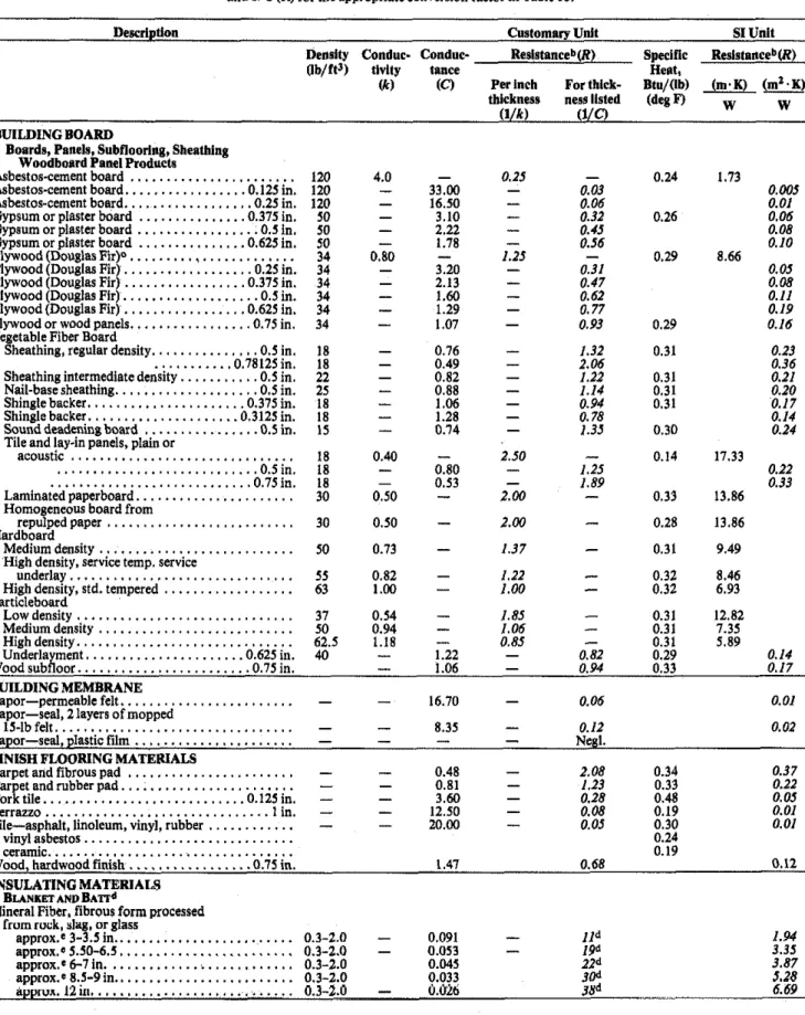
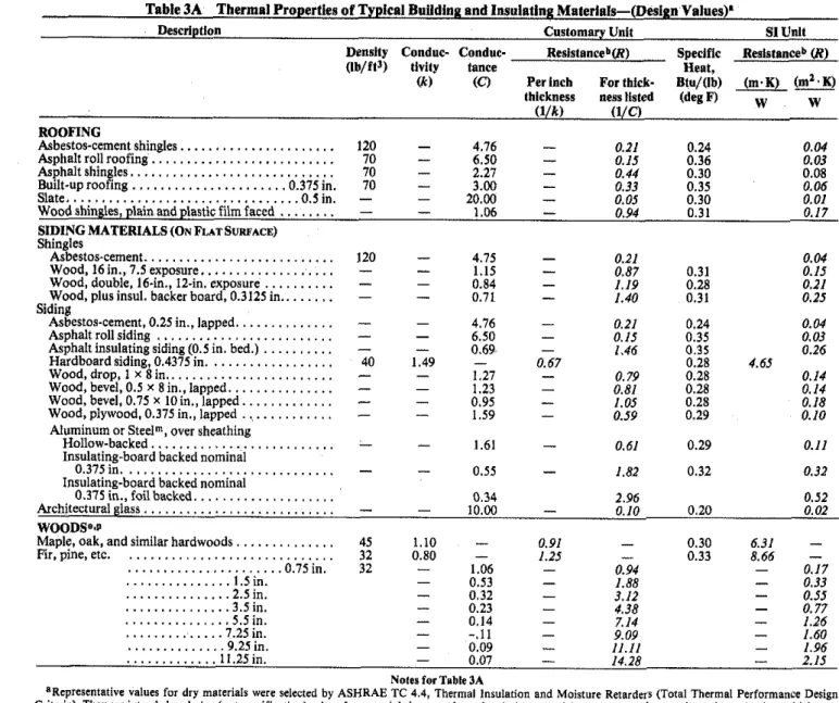
OVERALL COEFFICIENTS A N D T H E I R PRACTICAL USE
The values in Tables 1, 2, 2C, 3A, and 3B for component elements and materials were selected by ASHRAE Technical Committee 4.4, as representative. They are based on available published data obtained by the guarded hot plate method (ASTM C177). heat flow meter method ASTM C518), or by the guarded hot box method (ASTM C236). Because of variations in commercially available materials of the same type, not all of these selected representative values will be in exact agreement with data for individual products. The value for a particular manufacturer's material can be secured from unbiased tests or from guaranteed manufacturer's data.
The most exact method of determining the heat trans- mission coefficient for a given combination of building materials assembled as a building section is to test a represen- tative section in a guarded hot box. However, it is not prac- ticable to test all the combinations of interest. Experience has indicated that U-values for many constructions, when calculated by the methods given in this chapter, using accurate values for component materials, and with corrections for framing member heat loss, are in good agreement with the values determined by guarded hot box measurements, when thereare no freeair cavities within theconstruction.
Remember, the values shown for materials used in calcu- lating overall heat transmission are representative of laboratory specimens tested under idealized conditions. In ac- tual practice, if insulation is improperly installed (for exam- ple), shrinkage, settling, insulation compression, and similar factors may have a significant effect on the overall U-value numbers. Materials that are field fabricated, and consequent- ly especially sensitive to the skills of the mechanic, are especially prone to variations resulting in performance less than the idealized numbers.
Simplified Procedure f o r Determining
U-
Values Tables 4A through 4K illustrate the procedure which enables the engineer to determine and compare values for many types of construction. To determine the U-value for uninsulated construction, use Tables 4A through 4K; for pre- engineered metal buildings use Table 4L. The benefit derived from addition of insulation materials is shown in Tables 5A and 5B. The average U-value is then determined by Eq9.
Ad- ditional summer values for ventilated and nonventilated attics are given in Table6.
This simplified wocedure provides
a
means of evaluating economic ionsideiations involved in selection of insulating material, as adapted to various building constructions.Special attention must be given to vapor retarders, outlined
in
Chapters 20 and 21. Moisture from condensation or other sources reduces the heat flow resistance of insulation.Values Used in Calculation of U-value Tables
Tables 4A through 4K are based on values given in Tables 1, 2, and 3A. The following conditions have been used to calculate the U-value by including framing members o r other areas of through conduction.
heat storage.
Surrounding surfaces at ambient air temperatures.
Exterior wind velocity of I5 mph for winter (surface R
-
0.17) and 1.5 mph for summer (surfaceR = 0.25).Surface emittance of ordinary building materials r
-
0.90. Eq9
is used to correct for the effect of framing members.where
U... = average U-value for buildinn section.
6
= ~ - v & e for area betwccn framing members. U, = U-value for aea backed by framing members.S = percentage of area backed by framing members.
For those systems with complicated geometry, U., should be measured by laboratory tests on a large, representative area of the building section including the framing system.
Example3: Parallel heat flow through framing (studs, joists, plates, furring, etc.) and insulated areas is calculated by Eq 9. Consider a frame wall with R-11 insulation, a U,-value across the insulated space of 0.069 ( R
-
14.43), and a Us-value across the framing of 0.128 (R = 1.81). Assuming a 20% framing (typical for 16-in. in O.C. fram-ing including multiple studs, plates, headers, sills, band joists, etc.), the average U-value of this wall can becalculated.
For a frame wall with %in. O.C. stud space, the framing factor is estimated at 15%. In this case. the average U-value becomes 0.018. Depending on the care and installation of the insulation, U-values ob- tained in practice may be higher than those calculated here.
In construction involving air spaces, the U-values shown are calculated for areas between framing. See examples in Table 4 if an allowance is to be made for this effect.
To condense the tables. an average resistance value (avg R) has been used in some tables for iypes of materials having approximately the pamc thermal resistance values. The difference bnwm the average value and the exact value for any given material usually causes no significant change in the resulting U-value.
Actual thicknesses of lumber wumedto bem/ollows:
Nominal Actual Nominal Actual
...
...
1 in. (S-2-S) .0.75 in. 8 in.. .1.25 in.
...
...
2 in. (S-2-S) 1.5 in. 10 in.. .9.25 in.
...
...
3 in. (S-2-S) .2.5 in. 12in 11.25in.
...
4 in. (S-2-S) .3.5 in Finish flooring
...
6in.. ..5.5in. (maple or oak)
....
.0.75 in. Note that the effects of poor workmanship in construction and installation have an increasingly greater percentage effect on heat transmission as the U-value becomes numerically smaller. Failure to meet design estimates may be caused by lack of attention to exact compliance with specifications. A factor of safetf may beemployedas aprecaution when desirable.Caution
Although the validity of calculating U-values for all the types of constructions in Tables 4A through
4K,
5A, 5B,6,
and 7 has not been fully demonstrated, calculated values are given because measured values are not a ~ a i l a b l e . ~ It is
em-
phasized where calculated values are shown in this chapter they are for the convenience of the reader.
In calculating U-values, exemplary conditions of com- ponents and installations are assumed (i.e., that insulating materials are uniformly of the nominal thickness and con- ductivity, air spaces are of uniform thickness and surface temperatures, effects due to moisture are not involved, and
CHAPTER
23
1981
Fundamentals Handbook
installation details are in accordance with design). Some evi-
sulation and a U,
=0.206 with adjustment for framing. Refer to
dence of departures of measured from calculated values for
Table
5.4,left-hand column. Enter table
atU
-
0.20. For improve
certain insulated censtructions is given in Building Materials
m a t of thermal performance of the designed section to V
-
0.07,
and
R~~~~~ BMS 151, ~
~
~
B~~~~~
i
~
of
stan-
~
a
l
move horizontally to (U-
0.08) or (U
=0.06). Read vertically to top
of columns, finding that R
= 8andR
=IZrespectively. Interpolating
dards. To provide a factor of safety to account for departures
to the desiredu =
0,07,
it is seen that material havingan
R.valueof constructions from requirements and practices, some may
loor
satisfy therequirement,wish to moderately increase the calculated U-values of the in-
Table
5B is
constructed and used
to Table 5A.
"Iated
walls*
andceiling
Obtainedfrom
However, after having selected the desired &value for a roof
Tables 4A through 4K before making adjustments for fram-
deck
insulation, the values
are shown in conductance
of
ing (as indicated in Eq 9).
roof deck insulation. This facilitates specification of
Where reflective air spaces are involved in building con-
materials, since
roof
deck insulations
are
available by
con-
struction, caution should be exercised in use of values found
ductance values
(".in Table 2. The resistance values shown are achievable under
ideal conditions but are not normally achieved in standard
building construction because of surface irregularities, air
ADJUSTMENT FOR FRAMING
leakage, etc. Air spaces created by lapped metal siding should
Adjustment for parallel heat flow through framing and in-
be treated as nonreflective space. Even where an air space is
~ulated
areas may be made by using Eq 9. (See Example 3.)
gpurposely created as with furring strips or bdck veneer, tests
show that the resulting air space resistance is less than values
CURTAIN WALLS
found in Table 2. Where reflective air spaces constitute a ma-
Cufiain
wallconstructions present
a
of
jor share of the installed resistance of the insulation, increases
metals, insulating materials, and thermal bridges. Few panels
of U-values
UPto 25% for applications where heat flow is
,,
of true sandwich
construction
for
which the
thermal
Or
upward' and up
to
'OVowhere heat
flow,is
characteristics can be computed by combining the thermal
downward' appear reasonable'
Onthe
basis
Ofpresent
In-resistances of the several layers. Many panels have ribs and
formation. However, to accurately determine thermal
stiffeners which may
complicated heat flow paths
for
resistance values of multiple air spaces, tests on the actual
which
itis very difficult
to calculate the heat
transfer
coeffi-
construction should be conducted.'
cients with reliability. Coefficients for the assembled sections
INSULATED CONSTRUCTIONS-HOW
TO USE TABLES 5A AND
5B
In Tables 4A through 4K, U-values are given for many
common types of building wall, floor, and ceiling construc-
tions. For any of these constructions that contain an air space,
the tabulated U-value is based on the assumption that the air
space is empty, and its surfaces are of ordinary building
materials of high thermal emittance, such as wood, masonry,
plaster, or paper. The exception is the example shown in
Table 4K where the construction utilizes a reflective air space
under winter and summer heat flow conditions. Considerable
benefit in reducing the heat transmission coefficient of acon-
struction can be effected by application of thermal insulating
materials in the air space.
Table 5A provides a means of determining, without calcula-
tion, the U-value of the between-framing area of various types
of construction with added insulation installed in the air
space. The left column of Table 5A refers to the U- or
R-values of designed building sections. The right-hand
or-
tion of the table consists of aiabulation of U-values resuiting
from the combination of U- or R-values shown in the left col-
umn with the addition of the R-values heading each column.
In order to use Table SA, the designer enters the left column
with a known U- or R-value of a designed building section.
Proceeding horizontally across the right-band portion of the
table, he will find U-values showing improved performance
resulting from addition of thermal resistances as shown at the
head of each column.
Any and all U-values are based on a series of assumptions
as to nominal characteristics. Common variations in condi-
tions, materials, workmanship, etc., cat1 illlruduce much
greater variations in U-values than the vnriations rcsulting
f m
the assumed mean temperatures and temperature dif-
ferences described. From this, it is also clear that the use of
more than two significant figures in stating a U-value may
assume more precision than can possibly exist.
Example of the Use of Table 5A
Example 4:
Table
4Ashows a wood frame construction without in-
should be determined on a representative sample by the
guarded hot box method (ASTM C236) for sections which
have no free air cavities within the construction. In lieu of an
ASTM 236 test for these complex sections, a heat transfer
coefficient may be estimated by techniques shown in Ref 16.
VENTILATED ATTICS: SUMMER CONDITIONS
(HOW TO USE TABLE 6)
Table 6 is intended to be used with Table 4K (heat flow
down), Table 5A, and
Eq9, or when ceiling resistance is
known. Its purpose is to determine heat flow resistance of the
attic space under varying conditions of ventilating air temper-
atures and rates, ceiling resistance, roof or sol-air tempera-
tures, and surface emittances.' Ventilating air temperature is
the outdoor design temperature.
The total resistance, R
=1/U, obtained by adding the ceil-
ing and attic resistances, can be converted to a U-value so that
the heat gain may be calculated. The applicable temperature
difference is that difference between room air and sol-air
temperature or between room air and roof temperatures. (See
footnoted, Table 6.)
Table 6 may be used for both pitched and flat residential
roofs over attic spaces. When there is an attic floor, the ceiling
resistance should be that which applies to the complete
ceiling-floor construction.
BASEMENT FLOOR, BASEMENT WALL, AND
CONCRETE SLAB FLOOR COEFFICIENTS
.
The heat transfer through basement walls and floors to the
ground depends on: ( I ) temperature difference between the air
wilhin thr room and thatof the ground: (2) material con-
stituting thc wall or floor; and (3) conductivily
of
Urwaur-
rounding earth. Conductivity of the earth will vary with local
conditions, and is usually unknown. Laboratory tests6 in-
dicate a heat flow of approximately 2.0 Btu/h
.
ft2 through
an uninsulated concrete basement floor, with a temperature
difference of 20 deg F between basement floor and the air
temperature 6 in. above the floors. The U-value 0.10 is
sometimes used for concrete basement floors on the ground.
Design Heat Transmission Coefficients
For more detailed procedures, see Chapter 25 (text and Tables
2 and 3), and Refs 7, 17, and 18.
For basement walls below grade only, the temperature dif-
ference for winter design conditions will be greater than for
the floor. Test results indicate a unit area heat loss, at
midheight of the basement wall portion below grade, of ap-
proximately twice that of the same floor area.
For concrete slab floors laid in contact with the ground at
grade level, tests7 indicate that, for smallfloorar&(equal to
that of a house 25 ft square). the heat loss may be calculated
as proportional to the length of exposed edge rather than total
area. This amounts to 0.81 Btu/lh)llinear ft of exposed edge)
(deg F difference between the indoor air temperakre and the
average outdoor air temperature). Note that this may be ap-
preciably reduced by insulating under the ground slab and
alona the edges between the floor and abutting walls. In most
-
calc2ations;if the perimeter loss is calculated accurately, no
other floor loss need be considered. Chapter 25 contains data
for load calculations and gradient valuebf below grade walls
and floors.
filtration. Additional information is available in Chapters 22
and25.
CALCULATING SURFACE TEMPERATURES
In many heating and cooling load calculations, it is
necessary to determine the inside surface temperature or the
temperature of the surfaces within the structure. The resis-
tances through any two paths of heat flow are proportional to
the temperature drops through these paths, and can be
ex-pressed as:
R
1,-
(tl-
18)
(10)
R,
(11
-
to) whereR, =the resistance from the indoor air to any point in the
structure at which the temperature is to be determined,
R2
-
the overall resistance of
thewall from indoor air to outdoor
air.
f, =
indoor air temperature.
r-
=temaeratureto be determined.
1:
=outdoor air temperature.
GLASS AND DOOR COEFFICIENTS
Example J:
Determine the inside surface temperature for
a w dThe U-values given in Table 8 for flat glass, glass block,
having an overall coefficient of heat transmission
U= 0.25,indoor
airand plastic panels were obtained from ASHRAE Research
temperature
= 70 F.outdoor air temperature
=-
20 F,and
hi-
1.46Reportss in cases where the panels have been tested. In other
(seeTable
I).insiances, values were comp;ted using procedures outlined in
Chapter 27. Values in Table 9 for doors were calculated or
Solution:taken from availabie published papers. For winter conditions,
R,
= l/h,-
V1.46 = 0.68an outdoor surface conductance of 6.0 Btu/h. ftz
.
F was
used; for summer conditions, 4.0 Btu/h
.
ft'
.
F. The indoor
R,
= 1 / U = I/O.25 = 4.00surface conductance was taken as 1.46 Btu/h
.
ft'
.
F for
vertical surfaces, 1.63 for horizontal surfaces with heat flow
Then, byEq 10:
up, and 1.08 for horizontal surfaces with heat flow down. The
outdoor surfaces conductances are for wind velocities of 15
- = 0.685&
and 7.5 mph, respectively. Adjustments for other wind
4.000 70-
(-20)velocities may bemade using factors in Table 10.
All values are approximate, since some parameters which
I* = 54.6 Fmay
have
effects
were not -considered' For
Example 6:Determine the temperature
ofthe bottom
of a4-in, in.
acamples in
an
actual installation, Ihe
indoor
surface
a
sulated concrete roof slab to which has been glued 0.5-in. acoustical
glazing panel may be exposed to nearby radiating surfaces,
tile (C- 0.80) asthe interior finish. The roof-ceiling overall coeffi-
such as radiant-heating panels or exposed windows in ad-
cient of heat transmission,
U,is
0.14for heat flow up. The indoor air
jacent or opposite walls having much higher or lower tem-
temperature is assumed to be
70 F,and the outdoor air temperature,
perature than the indoor air. Use of the listed U-value
-
ZOF.assumes that the surface temperature of surrounding bodies is
equal to the ambient air temperature. Air movement across
Solu'ion:the indoor surface of a panel, such as caused by outlet grilles
in the sill, will increase the U-value.
Shading devices such as venetian blinds, draperies, and
roller shades will reduce the U-value substantially if they fit
tightly to the window jambs, head, and sill, and are made of a
nonporous material. As a rough approximation, tight-fitting
shading devices may be considered to reduce the U-value of
vertical exterior single glazing by 25% and of vertical exterior
double glazing and glass block by 15%. These adjustments
rn
should
not
be
considered in choosing heating equipment,
hutmay be used for calculating design cooling loads.
For panels not vertical or horizontal, such as sloped glass in
some types of skylights, calculation procedures outlined in
.
Chapter 27 should be followed. Since data are presented for
only vertical, horizontal, and 45-degree sloped surfaces and
air spaces, an orientation which most closely approximates
the application condition could be used (see Chapter 27).
ESTIMATED HEAT LOSS DUE TO INIlLTRATION
Table 7 lists factors which, when multiplied by the room or
building volume, will give the estimated heat loss due to in-
Then, by Eq 10:
The concrete surface temperature is of interest since
reference to a osychrometric chart or table will show that
moisture cond&&tion
can
occur on this surface under the
above conditions (46.5
0
if the relative humidity in the
room
exceeds about 44%. Additional roof insulation should
be con-
sidered above the slab to avoid condensation at this point if
lugher relative humidities in the room are anticipated.
The same procedure can be used for determining the temp-
erature at any point within the structure.
-A chart for determining inside wall surface temperature is
given in Figs. 7 and
8,
Chapter 8,1980 SYSTBM~VOLIJM~.
23.8
CHAPTER 23
1981 Fundamentals Handbook
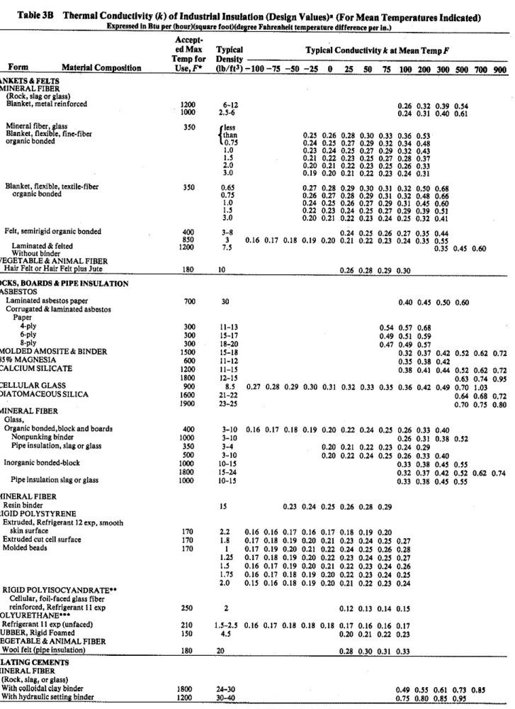
CONDUCTIVITY OF INDUSTRIAL INSULATIONS
T h e conductivities of various materials used as industrial insulations are given in Table
3B.
They are given as functions of the mean temperatures o f the arithmetic mean of the inner and outer surface temperature of the insulations.BARE SURFACE HEAT LOSSES-FLAT
SURFACES AND PIPE
Heat losses from horizontal bare steel pipes, based o n tests at Mellon Institute and calculated from the fundamental radiation and convection equations (Chapter 2), are given in Table 11. This table also gives the heat losses
or
surface con- ductances for flat, vertical, and horizontal surfaces f o r sur- face temperatures up t o 1080F
with the surrounding air at80
F.
The surface per linear f t of pipe is given in the second col- Fig. 5 Heat Flow through Cylindrical Surfacesumn o f Table 11.
.
Heat losses from tarnished copper pipe
and
tube9are
givenin Table 12. The surface per linear ft of
tube
is given in Table k = thermal conductivity of insulation at mean temperature,13. Table
1, SectionA,
also gives surfaceconductances
for L = Btu thickness of insulation, in..
in./h.
ft" F. flat surfaces of different emittancesand
orientations in con- I, = temperature of ambient air,F.
tact with still air. Table 14 gives area, in ft2, of flanges and to = temperature of inner surface of insulation,
F.
fittings for various standard pipe sizes. These tables can be I, = temperature of outer surface of insulation, F. used in estimating the amount o f insulation reauired.-
r. = inner radius of insulation. in.Example
7
shows how the annual heat lossfrom
uncovered rl.r2..:
= outer radius of intermedi~telayers of insulation, in. pipemay b ecomputed
fromthe
datain
TableI I.
R,
= surfaceresistance-
1/h = ftz.
F.
h/Btu.h
-
surfaceconductancecoefficient, Btu/h.
ft'.
F. Example 7: Compute total annual heat loss from 165 ft of 2.in. log, = natural or Napierian logarithm.bare pipe in service 4000 h / y . The pipe is carrying steam at 10 psi pressure and is exposed to an average air temperature of 80 F.
Solution: The pipe temperature is taken as the steam temperature,
heat
flow per ft2of pipe
surface,
use:
which is 239.4 F, obtained by interpolation from Steam Tables. Thetemperature difference between the pipe and air
-
239.4-
80 = 159.4 40'
4~ (rs/ro) (13) F. BY interpolation in Table 11 between temperature differences of150 and 7.03 F, heat loss from a 2-in. pipe at a temperature difference where
of 159.4 F is found to be 2.615 Btu/h
.
ft2.
F. Total annual heat loss = rate of heat transfer per square foot of pipe surface, from the entire line = 2.615 x 159.4 x 0.622 (linear ft factor) x 165 ~ ~.
ftz,
~ / h(linear ft)x4000(h) = 171 millionBtu. For steady state conditions, heat flow throuah each successive
HEAT FLOW CALCULATIONS
material is the same. However, the temperature drop through each material is proportional to its thermal resistance. The terms which appear in the denominators of Eqs 11 and I2 represent the resistances In calculating heat flow, Eqs 11 and 12 a r e generally used. to heat flow,Eq l1
is
for flatsurfaces
(Fig. 4),and Eq
l2is
for The heat transferred is inversely proportional to the sum of the cylindrical surfaces (Fig.5).
resistances (R,+
R2+ .
..+
R.)
of the system. The various tem-perature dropiin thesystem are proportional to the resistances.
t o
-
to Theassumptions used for calculations of heat loss areusually:''
'
( L ~ / k l )+
( L ~ / k z )+
R8
(I1) perature of fluid in the pipeor container. I, -temperature at inner surface of insulation equal to the tem-to
-
t.
9 s
-
1.-
still air ambient temperature = 80F.lrslog.(r~/ro)l/kl
+
[r,log,(r,/r,)l/k2+
R,
(I2) ro-
inner radius of insulation = outside radius of iron pipe.r, = outer radius of insulation
-
r,+ L.where Example 8: Compute heat loss from a boiler wall if the interior in-
q, = rate of heat transfer per square foot of outer surface of sulation surface temperature is 1100 F and ambient still air insulation, Btu/h
.
ft2. temperature is 80 F. The wall is insulated with 4.5 in. of mineral fiberblock aqd0.5 in. of mineral fiber insulating and finishingcement. Solullon: Assume that mean temperature of the mineral fiber block Is 700
F,
mcan tcmporature of rllt irr~ulalirlg cement is 200 F, andR, = 0.60.
.
From Table 3B, k l = 0.62 and k2 = 0.80. Then: 1100
-
80 = - IOU)"
= (4.5/0.62)+
(0.5/0.80)+
0.60 8.48R , . I l h
= 120.2 Btu/h
.
ft2As a check, from Fig. 6, at 120.2 Btu/h
.
ft2,R,
= 0.56. The mean temperature of the mineral fiber block is:(4.W0.62 = 7.26/2
-
3.63)1
Design Heat Transmission Coefficients
i*
FIE.
6
Heat Transmisslonvs.
Surface Reslslancefor
Flat and Cyllndrlc~l Surlaces
(Surface Enltlmmce 0.85 lo 0.90 In Sllll AlrJ
The mean temperatureof the mineral fiber block is: 1100
-
(3.75/8.69) (1020) = 1100-
440-
660 F Themean temperature of theinsulating cement is:From Table 3B, at 661 F, kI
-
0.60, and at 183 F, k2 = 0.79. Since R k t , and k2 do not change at these values, q, = 117.4 Btu/h.
fti).Example 9: Compute heat loss per ft2 of outer surface of insulation if pipe temperature is I200 Fand ambient still air temperature is 80 F. The pipe is nominal 6-in. iron pipe, insulated with a nominal 3 in, of diatomaceous silica as the inner layer and a nominal 2 in. of calcium silicate as theouter layer.
Solution: From Tabie 15. r, = 3.31 in. A nominal 3-in. thick diatomaceous silica insulation to fit a nominal 6-in. iron pipe is 3.02 in. thick. A nominal 2-in. thick calcium silicate insulation to fit over the 3.02-in. diatomaceous silica is 2.08 in. thick. Therefore, r, = 6.33 in.;
r,
= 8.41 in.Assume that the mean temperature of the diatomaceous silica is MXI F, the mean temperature of the calcium silicate is 250 F, and R, =
n
... 5nFrom Table 3B. k,
-
0.66 and k2 = 0.42:From Fig. 6, at 76.0 Btdh
.
ft2, R, = 0.60. The mean temperature of the diatomaceous silica is:The mean temperature of the calcium silicate is:
FromTable 3B, kl = 0.72and k2
-
0.46. Recalculating:From Fig. 6, at 83.8 Btu/h
.
ft', R. = 0.59. Mean temperature of the diatomaceous silica is:I200
-
(3.78/13.36) (1120) = 1200-
317 = 883 F Mean temperature of the calcium silicate is:I200
-
(10.17/13.36) (1120) = 1200-
853 = 347 F From Table 3B, k, = 0.72 and k2-
0.46. Recalculating:Since R,, k,, and k2 will not change at 83.8 Btu/h
.
ft2, th~s is the final 9,.The heat flow per square foot of the inner surface of the insulation will be:
HEAT FLOW CALCULATIONS INVOLVING
BURIED PIPE LINES
Incalculatinn heat flow from or to buried nine lines. it is necessary to mLke an assumption as to the thermal properties of the earth. Because most soil or earth contains moisture. it is technically incorrect to report thermal conductivity.
able
17 gives theamarent
thermal conductivity values of various ;oils. ~ h e s c i a l u e s may be used as a guide when making heat flow calculations involving buried lines. See Ref 10 for discus- sion of thermal properties of soil. Ref 11 gives methods for calculating the heat flow that takes place between one or more buried cylinders and the surroundi&s.THERMAL CHARACTERISTICS AND RESPONSE
FACTORS FOR FLOORS, WALLS, AND ROOFS
Current methods for estimating the heat transferred through floors, walls, and roofs of buildings are largely based on a steady state or steady periodic heat flow concept (Equivalent Temperature Difference Concept). The engineer- ing application of these concepts is not complicated and has served well for many years in the process of design and selec- tion of heating and cooling equipment for buildings. However, competitive practices of the building industry sometimes require more than the selection or design of a single heating or cooling system. Consultants are requested to presenta
detailed comparison of alternative heating and cool- ing systems for a given building, including initial wstsas
wellas
short- and long-term operating and maintenance costs. The degree of sophistication required for costs may make it necessary to calculate the heating and cooling load for estimating energy requirements in hourly increments for a year's time for given buildings at known geographic locations. Because of the number of calculations involved, computer processing becomes necessary. The hour-by-hour heating and cooling load calculations, when based upon a steady heat flow or steady periodic heat flow concept, do not account for the heat storage effects of the building structure, especially with regard to net heat gain to the air-conditioned spaces.A heat transfer calculation to better account for randomly