XIII. CIRCUIT THEORY
Prof. S. J. Mason Prof. J. Granlund A. Ospina Prof. H. J. Zimmermann A. B. Lehman R. D. Thornton
A. A PREDETECTION DIVERSITY COMBINER
Bandpass multipliers and narrow-band crystal filters that are needed in the com-biner were constructed and investigated. Figure XIII-1 is a simplified version of a multiplier and filter as they might be arranged in the combiner.
The first grid of the 6AS6 multiplier may be biased to produce plate and screen cur-rents compatible with the ratings of the tube; the third grid should be biased almost to the
value that maximizes the transconduct-ance from grid No. 3 to plate.
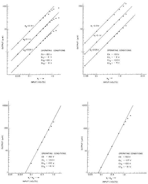
If we plot the multiplier output
6AS6 C,1 L L2 Kele3 against one of the inputs on
log-log paper, we expect straight lines with
e3 os.3t e, os t a
unit
slope. If el = e3, we expect straight8+ EC R
lines
with slope two.Figure XIII-2 shows
IEc
. the experimental curves (dotted lines)compared with the desired curves Fig. XIII-1. Multiplier and filter.
(solid lines).
The difference-frequency component is selected from the output of the multiplier by means of a narrow-band crystal filter. This extremely selective filter is needed in the combiner to obtain a short-time aver-age measure of the gain of the path from the transmitter to one of the receiving antennas. The filter represented in Fig. XIII-1 has a bandwidth of approximately 100 cps and a cen-ter frequency of 3.6 mc which may be varied ±120 cps by adjusting C9.
J. Granlund, A. Ospina
B. SYNTHESIS OF TWO TERMINAL-PAIR RESISTOR NETWORKS
Given a two terminal-pair resistor network, consider the effect of short-circuiting one pair as measured at the other pair. If the effect is large, then the two pairs are closely coupled and have driving-point resistances of the same order of magnitude. Conversely, if the driving-point resistances of the pairs are of different orders, then the pairs are loosely coupled, and short-circuiting one pair will not greatly affect the other. More precisely, let
zll z22
k = z llY11 and = max 1 z
e3=0.3 OPERATING CONDITIONS Eb = 150 V Ec= - 2 V Ec2= 100 V Ec3= - 4 V L j i l ll I I I I I I 1 1 0.03 01 10 INPUT (VOLTS) INPUT (VOLTS) OPERATING CONDITIONS Eb = 150V Ecl = - 2 V Ec = 100 V Ec3 = - 4V INPUT(VOLTS) INPUT (VOLTS) 1000 100 OPERATING CONDITIONS Eb = 150 V Ec = -2.0V Ec2 1=00 V Ec3 -4.1 V 0.03 0.1 e = e3 INPUT (VOLTS) OPERATING CONDITIONS Eb 150V Ec = -27V Ec2 = 100 V Ec3 = - 3 IV 0.03 0.1 0,3 1.0 e, = e INPUT (VOLTS)
Fig. XIII-2.
Curves of multiplier output versus signal input.
101
1000
(XIII. CIRCUIT THEORY)
Then it can be shown that kk < k + k!. Thus, if k or I equals 2, the other cannot exceed 2.
THEOREM: A necessary and sufficient condition that four positive real numbers
-1 -1
Y1 1l zll' Y2 2, z2 2 be the four driving-point conductances of a two terminal-pair
resistor network is that yllll = Y2222 and22 11 11 <Yl +1Y22" PROOF:
-1
Necessity: The necessary conditions y11z11 = Y2 2z2 2 and Zll 11 are well known
(1). Consider the same two terminal-pair network with each resistor replaced by a switch. Let Z 1 be the switching function of the network viewed from
terminal-pair 1, Z2 the function as viewed from pair 2, Y1 the function as viewed from pair
1 with pair 2 short-circuited, and Y2 the corresponding function viewed from pair 2 with pair 1 short-circuited (where
n
corresponds to a series connection and U cor-responds to a parallel connection). As each "path" in Y1 is either a "path" in Z1
or a "path" in Y22' it follows that Y1C 1UY 2 . Symmetrically, Y2 Z2 Y 1 If we make use of a theorem relating switching functions and resistance functions (2),
-1 these lattice (switching function) inequalities imply that yll <
Z11 2 2 and
-1 1 -1
22 z22 y1 1. The latter inequality is equivalent to z22 z1 under
the assumption that yl 1
z
11 = Y2 z 2222Sufficiency: The following network with conductances
-1 12
a = ll- ( 11 2 2 - ll Y2 2) c
b
2 2 -z
-1 1/2b = 22 11Y22 - Zll Y22 (I) a b (2)
-1
/2
c = YllY22 - Zll 2 2
---is sufficient.
The necessity proof, with proper symbolism, is applicable to some one-parameter network theories whose properties are quite different from those of resistor networks. For example, one such network theory admits neither Y-A transformations nor bridge-balancing. This type of proof can also be extended to n terminal-pair networks.
A. B. Lehman
References
1. For example, E. A. Guillemin, Introductory Circuit Theory (John Wiley and Sons, Inc., New York, 1953), pp. 153-161.
-1 -1
(Zll is the driving-point conductance measured across pair 1; z 1, the conductance measured across
terminal-pair 2; yll the conductance measured across terminal-pair 1 with terminal-pair 2 short-circuited; and y2 2' the corresponding conductance
measured across pair 2 with pair 1 short-circuited.)
2. A. B. Lehman, Lattice order of two-terminal resistor networks, June 1956, page 5, Theorem 2 (unpublished).