HAL Id: hal-03033027
https://hal.archives-ouvertes.fr/hal-03033027
Submitted on 1 Dec 2020
HAL is a multi-disciplinary open access
archive for the deposit and dissemination of
sci-entific research documents, whether they are
pub-lished or not. The documents may come from
teaching and research institutions in France or
abroad, or from public or private research centers.
L’archive ouverte pluridisciplinaire HAL, est
destinée au dépôt et à la diffusion de documents
scientifiques de niveau recherche, publiés ou non,
émanant des établissements d’enseignement et de
recherche français ou étrangers, des laboratoires
publics ou privés.
Rotating Spokes, Ionization Instability, and Electron
Vortices in Partially Magnetized E x B Plasmas
Jean-Pierre Boeuf, Masayuki Takahashi
To cite this version:
Jean-Pierre Boeuf, Masayuki Takahashi. Rotating Spokes, Ionization Instability, and Electron Vortices
in Partially Magnetized E x B Plasmas. Physical Review Letters, American Physical Society, 2020,
124 (18), �10.1103/PhysRevLett.124.185005�. �hal-03033027�
Rotating spokes, ionization instability, and electron vortices in
partially magnetized
𝑬 × 𝑩
plasmas
Jean-Pierre Boeuf1 and Masayuki Takahashi2
1Laplace, Université de Toulouse, CNRS, INPT, UPS, 118 Route de Narbonne, 31062, Toulouse, France 2Department of Aerospace Engineering, Tohoku University, Sendai, 980-8579, Japan
Regions of enhanced light emission rotating in the azimuthal direction are present in various 𝑬 × 𝑩 plasma devices. A kinetic model reveals that these “rotating spokes” are due to electron heating and enhanced ionization localized along a double layer at the interface between a region of large electric field and a quasi-equipotential region close to the anode potential. Electrons drifting along this interface are heated due to 𝛁𝐵 drift in the large electric field region. The formation of electron vortices due to the velocity shear in the double layer also contributes to electron heating. The possibility for spoke motion in the retrograde 𝑬 × 𝑩 direction as well as in the 𝑬 × 𝑩 direction, observed experimentally, can be reproduced and explained.
In plasma devices such as magnetrons1 and Hall
thrusters2 an external magnetic field 𝑩 is placed
perpendicular to the applied electric field 𝑬 to confine the electrons and allow ionization and plasma formation at low gas pressure. These devices are cylindrically symmetric, with 𝑬 × 𝑩 in the azimuthal direction to allow efficient electron confinement. In these “partially magnetized plasmas” electrons are strongly magnetized (electron Larmor radius 𝜌𝑒 small with respect to the plasma size 𝐿 ,
𝜌𝑒≪ 𝐿 ) while ions are not (𝜌𝑖≳ 𝐿). Turbulence and
instabilities resulting in anomalous transport and in the formation of coherent structures are present in partially magnetized 𝑬 × 𝑩 plasmas as in fusion or space plasmas but the physics of these instabilities is specific due the difference in the magnetization of electrons and ions3 and
to the existence of localized ionization regions. An example of instability that has been thoroughly studied in the recent years is the Electron Cyclotron Drift Instability (ECDI). Particle-In-Cell (PIC) simulations predict that the ECDI is present and controls electron transport in the exhaust region of Hall thrusters where a large axial electric field in the quasineutral plasma extracts and accelerates positive ions4-7. This azimuthal kinetic instability results
from electron Bernstein waves Doppler-shifted towards lower frequencies by the large electron drift velocity and was first identified in the context of collisionless shocks in space plasmas8, 9.
A longer wavelength instability, much easier to observe experimentally, is characterized by the rotation of a region of enhanced light emission (“rotating spoke”) at relatively low velocities (less than 10 km/s). Such moving macroscopic plasma non-uniformities have been reported in most 𝑬 × 𝑩 plasma devices. The first studies date back to the 1960’s when rotating-plasma machines were investigated as possible devices for fusion applications10.
The goal was to generate a large radial electric field E in the quasi-neutral plasma, for example in a coaxial electrode system with a strong axial magnetic field B. The plasma was expected to rotate at the velocity E/B. It was found experimentally that there was a maximum “burning voltage” of the discharge, i.e. a maximum plasma rotation velocity11. This limitation of the rotation velocity was
attributed to an abnormal ionization mechanism12 that was
related to the concept of critical ionization velocity (CIV)
introduced by Alfven13. In a model proposed Piel, Möbius
and Himmel14, the anomalous ionization was associated
with the formation and rotation of an azimuthal double layer where electrons were heated by a two-stream instability. More recently, a PIC simulation15, 16 of a
cylindrical magnetron discharge showed similarities with this model but the reason for the presence of the double layer was not elucidated and the question of the nature of electron heating in the double layer was not clarified.
Rotating spokes have also been observed in Hall thrusters17-20 and in pulsed planar magnetrons used in
plasma processing (HiPIMS, for High Power Impulse Magnetron Sputtering)1, 21. In some papers on Hall
thrusters17 or magnetrons22 the CIV concept has been
invoked to explain the presence of rotating spokes but there is no consensus on the physics of the rotating spokes in spite of important recent progress in the diagnostic and qualitative interpretation of these phenomena23, 24. An
intriguing feature of experiments on 𝑬 × 𝑩 devices is that spokes do not always rotate in the 𝑬 × 𝑩 direction. Retrograde motion (in the −𝑬 × 𝑩 direction) has also been observed in the low current regime of HiPIMS or in direct current (DC) magnetrons23, 24.
In this paper we present simulations of a recently published experiment by Ito, Young, and Cappelli25 on a
simple DC magnetron discharge, where self-organized structures rotating in the −𝑬 × 𝑩 direction were observed and analyzed with a high framing rate camera. On the basis of simulation results in conditions around this experiment and of published experimental results in other conditions, we propose a new insight into the physics of rotating spokes associated with an ionization instability in 𝑬 × 𝑩 plasmas. This new model of the physics of rotating spokes shares some qualitative aspects with but is clearly distinct from the CIV model of Ref. 14.
The experiment of Ito, Young and Cappelli consists of a small planar DC magnetron discharge in argon (gap 2 mm, diameter 5 mm, pressure 20 Pa) where the light emission is observed with a fast camera through a transparent planar anode. The magnetic field is generated by a ring magnet25.
Its component parallel to the electrodes varies from around 1 T at the cathode surface to about 0.1 T at the anode surface.
Figure 1: Contours of constant (a) electron density, (b) plasma potential, (c) electron mean energy, and (d) ionization rate at a given time in the conditions described in the text, corresponding to the experiment of Ref.25. The maximum values are respectively
4×10¹⁷ m-3, 260 V, 15 eV, 2×1025 m-3s-1. The spoke (ionization
region), plasma non-uniformity and potential structure move together up in the −𝑬 × 𝑩 direction at about 10 km/s while the electron vortices (local maxima in the electron temperature and ionization rate, and associated “holes” in the electron density) move down in the 𝑬 × 𝑩 direction at a velocity about ten times larger. Movies available in Supplemental Material at (URL).
The relatively large magnetic field and pressure are related to the small dimensions of the device and according to classical discharge scaling laws similar features should be observed for dimensions 10 times larger and magnetic field and pressure 10 times smaller.
The two-dimensional (2D) PIC-MCC model described in previous papers 15, 16, 26 has been used to simulate this
experiment. The simulation domain is defined by the axial and azimuthal directions 𝑥̂ and 𝑦̂. The axial length of the domain (cathode-anode distance) is 𝑑 = 2 mm , and the azimuthal length is 𝑤 = 4 mm. Periodic boundary conditions are assumed in the azimuthal direction. The magnetic field (in the −𝑧̂ = −𝑥̂×𝑦̂) direction is perpendicular to the simulation domain, and its magnitude 𝐵 varies axially according to 𝐵(𝑥) = 𝑎exp(− 𝑥2⁄2𝜎2) +
𝑏
, with
𝜎 = 0.35𝑑. 𝑎 and 𝑏 are chosen so that 𝐵(0) = 1 Tand
𝐵(𝑑) = 0.1 T. The discharge is sustained by ionization (calculated self-consistently in the Monte Carlo module) and secondary electron emission at the cathode due to ion impact. The argon electron-neutral and ion-neutral scattering cross-sections are the same as in Refs. 15, 16. Aneffective secondary emission coefficient 𝛾 is used in the simulation. The net flux Γ𝑒 of electrons leaving the cathode
is related to the ion flux Γ𝑖 by Γ𝑒= −𝛾Γ𝑖, i.e. an electron
coming back to the cathode is re-emitted. 𝛾 = 0.005 is used in the simulations. Electrons are emitted according to a semi-Maxwellian distribution at a temperature 𝑇𝑒=2 eV.
The applied voltage in the results presented here was 𝑈𝑑=
260 𝑉. The simulations were started with a uniform plasma density 𝑛𝑒= 𝑛𝑖= 2 × 10¹⁶𝑚−3. Most simulations were
performed on a 128x256 grid with about 300 particles per cell at steady-state (reached typically in less than 20 s).
In these conditions the simulation predicts the formation of an ionization instability (region of enhanced ionization, or spoke) moving in the −𝑬 × 𝑩 direction. When the simulation is performed with an azimuthal dimension of 8 mm instead of 4 mm, two similar spokes are present in the simulation domain and move in the −𝑬 × 𝑩 direction. The spoke velocity is around 10 km/s. These features (retrograde motion, spoke velocity, and periodicity) are in good agreement with the experiments of Ref. 25.
Figure 1 shows the space distribution of the main plasma properties at a given time in the simulation at steady-state. The plasma presents a strong azimuthal non-uniformity that creates a distortion of the equipotential lines. This distortion separates the plasma in two regions: one region of low electric field (lighter color region in Figure 1b) whose potential is close to the anode potential and a region of large axial electric field between the cathode and the quasi-equipotential region. A double layer is formed at the boundary between the two regions. We call this boundary (the ABCDE line in Figure 1b) “the interface” in the following. Note that the electric field is perpendicular to the equipotential lines so that the 𝑬 × 𝑩 electron drift follows the equipotential contours. Since the interface intercepts the anode, electrons are lost along this line (segments AB and DE of the interface on Figure 1b).
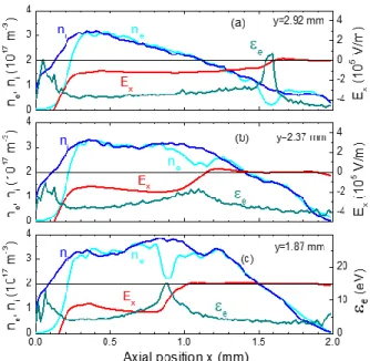
Figure 2: Axial profiles of the electron density, ion density, axial electric field and electron mean energy at different azimuthal positions indicated by the dashed lines in Figure 1.
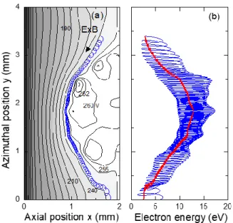
Figure 3: (a) Equipotential contours, and example of electron trajectory at a given time (same conditions as Figure 1), close to the double layer, on the left side of the BCD line of Figure 1. (b) Variations of the electron energy along the same trajectory. The initial electron velocity, at x=1.6 mm, y=3.4 mm, is 𝑣𝑥=
106m/s, 𝑣
𝑦= 0. The red line is the averaged energy calculated
assuming electron heating due 𝛁𝐵 drift.
The formation of the double layer at the interface is the consequence of the electron deficit due to losses at the anode not being entirely balanced by ionization along this line. We see on Figure 1d that ionization is enhanced along the interface and on the cathode side of the equipotential region (left side of the BC segment). It is interesting to note that in these conditions, most of the overall ionization takes place in this region, i.e. the plasma is sustained by the ionization instability. Ionization in the cathode region (generally important in glow discharges) is small in these conditions because of the large magnetic field and small collisional electron velocity parallel to the electric field in the cathode region leading to insignificant electron heating. The breaking of quasi-neutrality in the double layer can be clearly seen in Figure 2, which displays the axial profiles of the electron density, ion density, axial electric field, and electron temperature at the three azimuthal locations indicated by the white horizontal dashed lines in Figure 1a. One reason for the enhanced electron heating and ionization in the BC region is cross-field electron transport associated with the axial variations of the magnetic field (𝛁𝐵 drift27) in the large electric field region on the left of
the BC line. This is illustrated in Figure 3. This figure shows an example of electron trajectory (Figure 3a) in the vicinity of the interface, on the left side of the BCD segment, and the variations of the electron energy over the same trajectory (Figure 3b). The mean value of the electron energy increases by about 5 eV when the electron moves parallel to BC in the spoke front and decreases when the electron moves parallel to CD. The consequence of this electron heating is the intense ionization that takes place on the left side of the BC region in Figure 1d. The 𝛁𝐵 electron drift velocity, given by27 𝒗
𝛁𝐵= 1 2⁄ 𝜌𝑒𝑣⊥𝑩 × 𝛁𝐵/𝐵2
(𝑣⊥ is the electron velocity in the axial-azimuthal plane) is
directed in the azimuthal direction, downward along the BC segment and upward along CD. The electron heating along BC is given by 𝜕𝑡𝜀⊥= −𝒗𝛁𝐵. 𝑬 = 𝜀⊥𝐸𝑦⁄(𝐵𝐿) where 𝜀⊥
is the electron kinetic energy perpendicular to the magnetic field and 𝐿 = |𝐵 𝜕⁄ 𝑥𝐵|. The electron heating frequency
𝛼 = 𝐸𝑦⁄(𝐵𝐿) can be as large as 109 s-1 in the vicinity and
on the left side of the BC line (𝐸𝑦⁄𝐵 ≈ 5 × 10⁵m/s and
𝐿 ≈ 0.5 mm) leading to significant heating (the electron transit time along BC is in the ns range). This simple estimation is confirmed numerically on Figure 3b, where the red line corresponds to the electron mean energy calculated by integrating the expression above along the electron trajectory: 𝜀⊥= 𝜀⊥0− ∫ 𝒗𝛁𝐵. 𝑬𝑑𝑡. This clearly
shows that the 𝛁𝐵 drift plays an important role in electron heating in the conditions of Figure 1.
We note on Figure 3a that the electric potential presents local maxima of several volts above the anode potential in the quasi-equipotential region. These maxima are associated with the formation of electron vortices due to the electron velocity shear in the double layer. These vortices (apparent as electron density “holes” and local maxima of the electron mean energy and ionization rate in Figure 1) move along the double layer at the 𝐸 𝐵⁄ velocity where 𝐸 is an average value of the electric field in the double layer. The physics is similar to that of the diocotron instability observed in pure electron plasmas28 except that the electron
vortices form here in a local potential maximum rather than minimum of the potential, due to the positive space charge of the double layer. This is the reason why the vortices form “holes” instead of “clumps”28 in the electron density, as can
be seen in Figure 1a. Electron hole vortices were already observed in simulations of cylindrical magnetrons15, 16 (see
Fig. 11 of Ref.16). The distortion of the potential in the
electron vortex can also contribute to electron heating as can be seen in Figure 3. Note however that the electron trajectory of Figure 3 is calculated for an electric potential distribution assumed to be constant in time. The local potential maxima move along the double layer and the electron energy balance is actually more complex and is the result of an electron-wave interaction (see Supplemental Material at URL). Nevertheless we can see on Figure 1c and Figure 1d that the formation and motion of the electron vortices contribute to electron heating since local maxima of both electron mean energy and ionization rate appear at the vortex locations. Electron heating due to 𝛁𝐵 drift is important in the conditions considered and seems to be responsible for the stability of the spoke. In the absence of magnetic field gradient, electron heating associated with electron vortices and electron-wave interaction in the double layer may be sufficient to generate spokes as can be inferred from the simulation results of Refs.[15, 16].
The reason for the spoke motion in the −𝑬 × 𝑩 direction in the conditions of Figure 1 can be understood simply by the fact that the ionization region is located on the side of the plasma and potential maxima that is opposite to the
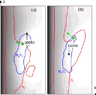
𝑬 × 𝑩 direction. The plasma and ionization region (spoke) apparently “move” in the −𝑬 × 𝑩 direction, i.e. in the region where new electrons and ions are generated by ionization. This is illustrated in Figure 4a. The question now is, why spoke rotation is also observed in the 𝑬 × 𝑩
direction in other experiments (HiPIMS23, 24). We
performed simulations in the same conditions as Figure 1 but with 𝐵(0) = 0.5 T instead of 1T (the electron current density emitted by the cathode was imposed and equal to 5 A/m2 in this simulation). In these conditions the simulations
predict spoke rotation in the +𝑬 × 𝑩 direction as illustrated in Figure 4b. The main differences between the two cases are 1) the position of the ionization region with respect to the plasma density, and 2) the direction of the ion flow in the spoke front. In Figure 4a new electrons and ions are generated in and above the location of maximum plasma density and ions are not expelled from the front by the electric field. In Figure 4b ions are expelled azimuthally from the front faster than they are generated by ionization. This can be simply formulated by writing the ion continuity equation 𝜕𝑡𝑛𝑖= 𝑆 − 𝛁.𝑛𝑖𝒗𝒊 at the starting point of the
arrows representing the ion flux in the spoke front in Figure 4 (𝑆 is the ionization rate, 𝒗𝒊 the ion mean velocity). In
Figure 4a, 𝑆 > 𝛁.𝑛𝑖𝒗𝒊 so 𝜕𝑡𝑛𝑖> 0 and the front moves in
the upward (−𝑬 × 𝑩) direction. The opposite is true for Figure 4b.
The conditions of Figure 4b are likely to be met when the azimuthal component of the electric field in the spoke front is larger than the axial component and/or for larger plasma densities. In any case the simulation results indicate that the same physics (electron heating along a double layer) is responsible of spoke rotation in the retrograde
𝑬 × 𝑩 direction as well as in the 𝑬 × 𝑩 direction.
Figure 4: Equipotential contours (grey), and lines of constant plasma density and ionization rate corresponding to 70% of their maximum values. The green arrows indicate the ion flux direction in the spoke front. (a) spoke rotation in the −𝑬 × 𝑩 direction, case of Figure 1, (b) rotation in the +𝑬 × 𝑩 direction, same conditions as Figure 1 with 𝐵(0) = 0.5 T instead of 1T. Movies available in Supplemental Material at (URL).
The main results can be summarized as follows. The small cross-field electron mobility is responsible for an instability (presumably of the Simon-Hoh type3, 26 in its
initial phase) that leads to an azimuthal distortion of the plasma potential and density. This distortion allows some electrons to flow to the anode along an equipotential line
connecting the cathode and anode regions. A double layer forms along this line, which lies at the interface between an equipotential region close to the anode potential and a lower potential region. Electron flow along this interface due to 𝑬 × 𝑩 drift. The double layer is generated by the drop in electron density due to electron losses to the anode along this line. Electron gain energy due to 𝛁𝐵 induced cross-field transport while drifting along the double layer toward regions of increasing electric field. The formation of electron vortices due to the velocity shear in the double layer also contributes to electron heating. Ionization is therefore enhanced in that region. The spoke can rotate in the −𝑬 × 𝑩 as well as in the +𝑬 × 𝑩 depending on the position of the plasma non-uniformity with respect to the ionization region and on the relative values of the axial and azimuthal components of the electric field in the spoke.
The main similarities of the mechanism described above with the CIV model of Ref.14 is the presence of a double
layer at the spoke front and the enhanced electron heating and ionization in that region but the reason for the formation of a double layer, the mechanism of electron heating, and the spoke velocity are distinct from those of the CIV model. Finally, we note that the conclusions of recent experiments23, 24 and of the present model are
converging on a number of points: existence of a double layer at the spoke front, energization of electrons around the double layer, possible rotation in the ±𝑬 × 𝑩 direction.
1 A. Anders, Journal of Applied Physics 121, 171101 (2017).
2 J.-P. Boeuf, Journal of Applied Physics 121, 011101 (2017). 3 A. I. Smolyakov, O. Chapurin, W. Frias, I. Koshkarov, I. Romadanov, T. Tang, M. V. Umansky, Y. Raitses, I. Kaganovich, and V. P. Lakhin, Plasma Physics and Controlled Fusion 59, 0140141 (2017).
4 J. C. Adam, A. Héron, and G. Laval, Phys. Plasmas 11, 295 (2004).
5 J. Cavalier, N. Lemoine, G. Bonhomme, S. Tsikata, C. Honore, and D. Gresillon, Phys. Plasmas 20, 082107 (2013). 6 T. Lafleur, S. D. Baalrud, and P. Chabert, Physics of Plasmas
23, 053503 (2016).
7 J. P. Boeuf and L. Garrigues, Physics of Plasmas 25 061204 (2018).
8 D. Forslund, R. Morse, and C. Nielson, Phys. Rev. Lett. 25, 1266 (1970).
9 M. Lampe, W. M. Manheimer, J. B. McBride, J. H. Orens, R. Shanny, and R. N. Sudan, Phys. Rev. Lett. 26, 1221 (1971). 10 J. M. Wilcox, Reviews of Modern Physics 31, 1045 (1959). 11 U. V. Fahleson, Phys. Fluids 4, 123 (1961).
12 G. Himmel and A. Piel, J. Phys. D: Appl. Phys. 6 (1973). 13 H. Alfven, On the Origin of the Solar System (Oxford
University Press, 1954).
14 A. Piel, E. Möbius, and G. Himmel, Astrophysics and Space Science 72, 211 (1980).
15 J. P. Boeuf and B. Chaudhury, Phys. Rev. Lett. 111, 155005 (2013).
16 J. P. Boeuf, Frontiers in Plasma Physics 2, 74 74 (2014). 17 C. S. Janes and R. S. Lowder, Phys. Fluids 9, 1115 (1966). 18 M. McDonald and A. D. Gallimore, IEEE Trans. Plasma Sci.
39, 2952 (2011).
19 C. L. Ellison, Y. Raitses, and N. J. Fisch, Phys. Plasmas 19, 013503 (2012).
20 M. J. Sekerak, B. W. Longmier, A. D. Gallimore, D. Brown, R. R. Hofer, and J. E. Polk, IEEE Trans. Plasma Sci. 43 (2015).
21 N. Brenning, D. Lundin, T. Minea, C. Costin, and C. Vitelaru, J. Phys. D: Applied Physics 46, 084005 (2013).
22 N. Brenning and D. Lundin, Phys. Plasmas 19, 093505 (2012).
23 M. Panjan and A. Anders, J. Appl. Phys. 121 (2017). 24 A. Hecimovic and A. von Keudell, Journal of Physics D:
Applied Physics 51, 453001 (2018).
25 T. Ito, C. V. Young, and M. A. Cappelli, Applied Physics Letters 106, 254104 (2015).
26 J. P. Boeuf, Phys. Plasmas 26, 072113 (2019).
27 F. F. Chen, Introduction to Plasma Physics and Controlled Fusion (Plenum Press, New-York, 1984).
28 A. Kabantsev, C. F. Driscoll, D. H. E. Dubin, and D. A. Schecter, J. Plasma Fusion Res. SERIES 4 (2001).