HAL Id: hal-02910227
https://hal.archives-ouvertes.fr/hal-02910227
Submitted on 1 Aug 2020HAL is a multi-disciplinary open access
archive for the deposit and dissemination of sci-entific research documents, whether they are pub-lished or not. The documents may come from teaching and research institutions in France or abroad, or from public or private research centers.
L’archive ouverte pluridisciplinaire HAL, est destinée au dépôt et à la diffusion de documents scientifiques de niveau recherche, publiés ou non, émanant des établissements d’enseignement et de recherche français ou étrangers, des laboratoires publics ou privés.
New measurement technique of liquid film thickness
distribution with high spatial and temporal resolution:
application to convective condensation in microgravity
Pascal Lavieille, Marco Azzolin, Arianna Berto, Patrick Queeckers, Andrey
Gluschuk, Benoît Schlegel, Stefano Bortolin, Marc Miscevic, Carlo Iorio,
Davide del Col
To cite this version:
Pascal Lavieille, Marco Azzolin, Arianna Berto, Patrick Queeckers, Andrey Gluschuk, et al.. New measurement technique of liquid film thickness distribution with high spatial and temporal resolution: application to convective condensation in microgravity. 14th International Conference on ”Two-Phase Systems for Space and Ground Applications”„ Sep 2019, Granada, Spain. �hal-02910227�
New measurement technique of liquid film thickness distribution with high spatial and temporal
resolution: application to convective condensation in microgravity
Pascal Lavieille1, Marco Azzolin2, Arianna Berto2, Patrick Queeckers3 Andrey Gluschuk3, Benoit Schlegel1, Stefano Bortolin2, Marc Miscevic1, Carlo Saverio Iorio3, Davide Del Col2
1Université Paul Sabatier - Laboratoire Plasma et Conversion d’Energie
118 route de Narbonne, Bat3R1, 31062 Toulouse Cedex 09, France
2Università degli Studi di Padova - Dipartimento di Ingegneria Industriale
Via Venezia, 1 – 35131, Padova, Italy
3Université libre de Bruxelles - Microgravity Research Centre
Av. F. Roosevelt 50, CP 165/62 - 1050 Brussels - Belgium
Pascal.lavieille@laplace.univ-tlse.fr, davide.delcol@unipd.it, ciorio@ulb.ac.be
Introduction
Prediction of condensing two phase flow (flow pattern, heat transfer and pressure drop) needs an accurate knowledge of liquid film thickness distribution. Indeed liquid film thickness is a key parameter to understand the main mechanisms inducing the instability and governing pressure drop and heat transfer. Unfortunately this liquid film is often very thin and unsteady. This thinness coupled with a highly dynamic change of slope of the interface make challenging the measurements of the liquid thickness. This lack of experimental data limits the validation and improvements of numerical or analytical model and so development of the laws that manage two-phase flow.
The present work proposes a technique to determine accurately with a high spatial and temporal resolution the liquid film thickness distribution inside a tube. This technique combines a high resolution punctual measurement system and high speed image acquisition of the flow inside a tube owning an external specific shape designed in order to magnify small liquid film thickness.
Limitations of standard visualizations
In the 62nd ESA parabolic flight campaign realized in June
2015 a shadowgraph method with a parallel light source has been used in order to determine temporal evolution of liquid film distribution of condensation flows in microgravity. The advantage of this measurement technique is to observe with a high temporal resolution (1500 Hz) the axial film thickness distribution at the top and at the bottom of the tube. In order to obtain quantitative measurements, distorsions induced by the cylindrical shape of the tube have been corrected using a ray-tracing model. This allows to convert the seeming thickness of the image into the real liquid film thickness present inside the tube. Two main limitations reduce the performances of this technique: the resolution of the measurement is limited by the spatial resolution of the camera and the liquid film can not be detected below a threshold value due to light deviation (figure 1). Another limitation induced by the cylindricity of the external shape of the tube is to produce a defocus of light which make ineffective or less effective point measurement techniques such as confocal chromatic or interferometric.
In order to overcome these limitations in the 70th ESA
parabolic flight campaign realized in Nov. 2018 a glass tube with a specifc external shape has been designed and realized.
Figure 1: Ray tracing of parallel light inside a tube where a thin
liquid film is distributed around the internal wall. The light deviation angle is too high to be collected by the CCD sensor of the camera.
Theoretical optical performances of the specific external tube shape
From the optical properties of the materials and the fluid, the shape of the external surface of the glass tube has been calculated in order to make detectable liquid film down to one micrometer, to produce a magnification of small liquid film thickness and to allow the use of punctual measuring sensors. The theroretical performances deduced from the ray tracing model are presented in figure 2.
Figure 2: Theoretical calibration curve of the tube with the
calculated specific external shape.
Magnification of small liquid film is obtained. Indeed from this calibration curve it can be deducted that when the liquid film thickness inside the tube is 50 µm, the camera will see the liquid film as if its thickness is equal to 267 µm. In that case even if the spatial resolution of the camera is 10 µm/pixel the liquid film thickness will be determined with an accuracy of 6% (knowing that when the seeming thickness is 277 µm the real thickness is 53 µm) instead of 20% when there is no magnifying effect. Figure 3 shows this relative accuracy according to the liquid film thickness inside the tube. With
such a camera resolution the relative accuracy fall down below 10% when liquid film thickness is higher than 20 µm and below 5% for liquid film thickness greater than 100 µm.
Figure 3: Relative accuracy in measuring film thickness as a
function of film thickness inside the tube, using a camera with a resolution of 10 µm/pixel.
Such magnification (figure 4) allows to combine high accuracy and large field of view with a high temporal resolution. For the 70th ESA parabolic flight campaign this
optical configuration has been used in order to measure liquid film structures at the top and at the bottom of the tube on a length of 13 mm with a camera frame rate of 1000 Hz.
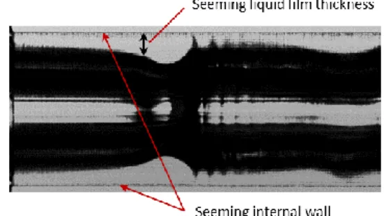
Figure 4: Example of image showing the magnification of liquid film thickness during microgravity inside a tube of 3.4 mm internal diameter.
Punctual measurement techniques
One of the main difficulties of this optical technique is the realization of the calculated external tube shape. Indeed it requires a high accuracy of the shape of the inner and outer surfaces but also of their relative position and roughness. Error in one of these parameters creates a modification of the calibration curve and reduces the capability to determine precisely the liquid film thickness. In order to overcome these difficulties and also to keep the possibility to determine more accurately liquid film thickness, punctual measurement sensors have been added.
The external surface of the tube has two flat surfaces that allow to use techniques analysing the reflected light properties to determine liquid film thickness. A white light interferometer and a confocal chromatic sensor have been placed respectively at the top and at the bottom of the tube. The white light interferometer used, allows to determine liquid film thickness between 0.5 µm to 100 µm with an accuracy of 10 nm. It is particularly well suited for small liquid film thickness. The main limitation is that the angle between the liquid-vapor interface and the tube surface must be small (roughly below 15°). The confocal sensor used can accept slope of the interface up to 28° and can measure liquid film thickness between 20 µm and 300 µm.
Thanks to these sensors and this optical configuration, the liquid film thickness can be measured simultaneously with the camera and one of these sensors at 1000 Hz. This accurate measurement allows to check and eventually correct the theoretical calibration curve of the machinning tube and then create a way to determine accurately the liquid film thickness distribution taking into account the distorsion induced by machining precision.
Such optical measurement set-up was used to study the gravity effect on the condensation of HFE-7000 inside a 3.4 mm internal tube diameter for mass flow rate between 30 and 55 kg m-2 s-1.
Experimental set-up
The experimental facility is similar to the one used for the 62nd
ESA Parabolic flight campaign (Azzolin et al. 2018) with two main loops: the refrigerant (HFE-7000) loop and the coolant water loop. The optical measurement section is placed between two heat exchangers (figure 5). The first heat exchanger is divided in three sub-sectors, the second one in two sub-sectors. These sub-sectors allow to determine quasi-local heat flux and heat transfer coefficient. The heat flux is obtained thanks to the determination of the water mass flow rate and the temperature difference measured with a copper-constantan three-junction thermopile. For each sub-sector, six T-type thermocouples embedded on the wall allow to deduce the heat transfer coefficient.
Figure 5: Layout of the experimental test section.
Effect of gravity, mass flow rate and quality on liquid film thickness distribution will be presented in the workshop.
Conclusions
A new technique to accurately measure the liquid film thickness distribution has been proposed and applied during the 70th ESA parabolic flight campaign. A specific designed
external tube shape has been realized to magnify the liquid film thickness and to easily detect, with a standard camera resolution, liquid film thickness down to few micrometer. This technique was coupled with confocal and white light interferometric sensors to reach submicrometric precision at a frequency rate of 1000 Hz.
Acknowledgements
The authors acknowledge the financial support of the European Space Agency through the MAP Condensation program ENCOM-3 (AO-2004-096).
References
M. Azzolin, S. Bortolin, L. P. Le Nguyen, P. Lavieille, A. Glushchuk, P. Queeckers, M. Miscevic, C. Saverio Iorio, D. Del Col, Experimental investigation of in-tube condensation in microgravity, International Communications in Heat