Publisher’s version / Version de l'éditeur:
Vous avez des questions? Nous pouvons vous aider. Pour communiquer directement avec un auteur, consultez la première page de la revue dans laquelle son article a été publié afin de trouver ses coordonnées. Si vous n’arrivez pas à les repérer, communiquez avec nous à PublicationsArchive-ArchivesPublications@nrc-cnrc.gc.ca.
Questions? Contact the NRC Publications Archive team at
PublicationsArchive-ArchivesPublications@nrc-cnrc.gc.ca. If you wish to email the authors directly, please see the first page of the publication for their contact information.
https://publications-cnrc.canada.ca/fra/droits
L’accès à ce site Web et l’utilisation de son contenu sont assujettis aux conditions présentées dans le site LISEZ CES CONDITIONS ATTENTIVEMENT AVANT D’UTILISER CE SITE WEB.
Internal Report (National Research Council of Canada. Institute for Research in Construction), 1998-03-01
READ THESE TERMS AND CONDITIONS CAREFULLY BEFORE USING THIS WEBSITE. https://nrc-publications.canada.ca/eng/copyright
NRC Publications Archive Record / Notice des Archives des publications du CNRC : https://nrc-publications.canada.ca/eng/view/object/?id=9cd7c646-e73d-44d7-8467-0a99b52d2bfb https://publications-cnrc.canada.ca/fra/voir/objet/?id=9cd7c646-e73d-44d7-8467-0a99b52d2bfb
NRC Publications Archive
Archives des publications du CNRC
For the publisher’s version, please access the DOI link below./ Pour consulter la version de l’éditeur, utilisez le lien DOI ci-dessous.
https://doi.org/10.4224/20386602
Access and use of this website and the material on it are subject to the Terms and Conditions set forth at Hygrothermal damage of building materials and components: state-of-the-art report on studies of hygrothermal damage and pApproach for damage assessments
http://irc.nrc-cnrc.gc.ca
H ygrot he r m a l Da m a ge of Building
M at e ria ls a nd Com pone nt s: St at e oft he
-Ar t Re por t on St udie s of H ygrot he r m a l
Da m a ge a nd Propose d Approa ch for
Da m a ge Asse ssm e nt s
N o f a l ,
M .
I R C - I R - 7 5 7
National Research Conseif natirrnal
1+
1
Council Canada de recherches CanadaHygrothermal
Damage
of Building
Materials
and
Components:
State-of-the-Alt Report
on
Studies
of Hygrothermal
Damage
and Proposed
Approach for Damage
Assessments.
(::I ST 1 / Ji3 TST NRC/i: t\!%lC: JRI: R e f S e r
H e c : ~ ? j v e d fin : 0 - : i - I?? ' 3 3
I-& t I- n.2 1. i-e L I ~ I- t, .
Mostafa Nofal
internal Report No. 757
Date of issue:
March
1998I n E ~ ~ C A I t - : = ! p f i r k I I - ~ < - t I t ~ t t ; - : f A N A L Y S E
J
This internal report, while not intended for general distribution, may be cited or referenced
This report is prepared for the Institute for Re-h in Construction (IRC) at the National Research Council
(NRC)
of Canada. The report d s e s existing theoreticaland
experimental methods for evaluating damage of construction materials and building envelopes.The
report a h identifies areas where research is needed, especiallyin
determining buiIdings' durability and
in
evaluating damage of the different construction materials. The review of the current l i t e m suggests that thereis
inadequateinformation a h a dmbiIity of materids and structures.
The
causes of buildingenvelopes damage are identified as both technical and functional,
The report is split to three parts and divided into ten chapters discussing and
presenting different mdeIling and measurement aspects
of
damage of variousconstruction materials. The first part
of
the report, included in Chapters 1 to 3,m m m i s e s the current philosophy
in
modellingand
measuring hygrothemd behaviourof construction materials. Chapter 1 introduces the problem of durability and - hygrothed damage of building materials. It states the objective of the c m n t study
and outlines the steps followed
in
completing this report. Chapter 2 m u m n a r k s thetheoretical basis
of
the mechanicsof
moistureand
heat tmmfZ:rin
inconstruction material h a w e modeIling hygmthemal damage requires physical, chemicaland
mechanical properties. Chapter 3 presents the existing experimental work on the materialcharacterisation and addresses experiments aimed at predicting the bekviour of construction materials in the laboratory under changing conditions,
The second part, documented
in
Chapters 4 to 8, discusses the-state-of-the-art en modelling and testing damage of construction materids and building envelopes. Chapter4 discusses the test methodology and procedures
used in
measuring damage ofbudding
materials. Chapter 5 describes c m t literature for estimating h y ~ tdamage ~ 1forwood materials. It identifies the different darnage mechanisms sf wood due to exposure
to hvgrothermal effects. Chapter
6
discusses the drunrtgein
brick
masonry.It
shows thatof materials mechanicaI and storage properties. Chapter 7 shows that concrete materSs
are vulnerable to cracking and corrosions of both comete
and
reinfbrcement materials.It also presents the problems in modelling concrete mic~ostructure and the chemical process lading to corrosions. Finally, Chapter 8 briefly sbws the damage of finish materials specially paint and bitumen-based materials.
The last part of the report presents detailed procedures of a novel approach for
assessing the strength of darnaged or undamaged construction materials. The proposed
approach, included
in
Chapter 9, would determine the complete mechanicat khaviour ofstructures made
h m
wood, brickand
concrete, including the impact of damageon
theresponse of structures. The p p o d method is using rigorous theories of mechanics,
inGIuding h c t m
and
damage mechanics, the theories of elasticity and pIasticity to characterise tk complete response of construction materials at any load level. Theapproach is based on measuring stifhess degradation caused by damage accumulation as
a r e d of hygrothemd and m e c ~ c a l loads. Chapter 10 also provides conclusions and
T
wodd like to take this opportunity to thankmy
colleagues, Wiliam Brown, Mike Swinton, MichaleI Lacasse, Achilles Karagiozis,and
Kumar Kumaran, at the Institute forResearch
in
Construction(Re),
National Research Council. Canada (NRC), who aresaving on the advisory committee of
the
project "Hjypthermal Dumage of Building materials and Componenfr". Their inputs md advice ate greatly appreciated.In
particular, I would like to thankDm
J. Beaudoin,K
Kumzlran, P, Mambercher,A. Kmgiozis, and
D.
Onysko, for their very constructiveand
thorough technical reviews of the various chapters of the report.This report is not regarded
in
anyway as an exhaustive review of the subject. The objectiveof this
study was to take a strategic position in regard to a new research project.In
this context, the fruit11 discussionsaad
useful assistance of DrsK
Kumaran, J.TABLE OF CON'lENTS
2 MECHAMCSOF THE PROBLEM
...
,.,...
9...
3.1 GENERAL...-
*...
...
,=...
HH..H
- *,.....
...
...
--
...
.
14 3.2 M ~ T E R L ~ L PROPERTIES...
-",*.
...
,-.
14 3.3 EXPERFMENTAL.
.
M ~ O D S.
...
.
.
.
.
,
.
..
18...
3.3.1 Lkfermimiorr of Storage Chmcferimmcs 18
3.3.2 Derermirmfion of Vapow Dimion C 4 c i e n t x
...
213.3.3 Determination ofCwiflmy transport Co@cients
... .
.
.
.
.
.
.
.
.. .
...
24...
3.4 SOLAR RADIATION EFFECTS
...
273.5 DIKU$$IONS
.,
...,--...-..
.
.
.
.
.
.
.
.
.
.
.
.
.
.
.
.
.
.
.
.
.
.
.
.
.
.
.
.
.
.
.
.
.
.
.
.
.
.
.
.
.
.
.
.
.
.
.
.
.
.
.
.
.
.
.
.
.
.
.
.
.
.N.N...NN N........
303.6 H Y C R ~ R M A L DAMAGE
...
31 3.7 Co~nusro~s...1...~...
.
325.1 GENERAL
...
.
.
... ., ...--...
425.2 DAMAGE TYPES
...-...
.*I...
...
425.2.1 SfntcfuraI Damage Model for h b e r
.
...
,
.
.
..
..
.
..
.
. 45...
5.2.2 Fungal Dunrage Mechisins and Mo&lling 52 5.3 RECENT STUDIES ON MOULD AND WOOWDDECAY FUNGI DAMAGE...
.
....,-.
60...
5.4 FrrYrvrsa WORK ON FUNGAL DAMAGE.
...
...
"...--....
... -.,.
61...
5.4. I M d Furrgi Damage 62...
5.4.2 Wood-&cay Fungi Damuge 69 5.1 C O N C L ~ I O N..."...
.r....
. . .
...*...*
,...
74 6.1 GENE-....,...
.,...
.,,... ... ...
. .
....
. .
76 6.2 FROST DAMAGL...,,...,,
...
..
I...n...n,...w,
*.*....
...*
..,...,..
..*... .-.,
.... .
78 6.2.1 V01uneh.i~ &pamion %y...
.
.
.
.
...
.
.
...
79 6.2.2 Ctystdlisdion.
Tlaeoly.
...
,
.
...-.
79...
6.23 m Z i c P m s m Kkwy 80 6.3 SALT CRYSTALLISATION..
..,,...,,...LILILI...LILILI...
...,,, . . .
. . .
...
...
83...
6.3.1 Salt CrystaIKfsation Mechanism 83 6.3.2 Brick Hychiun Stares...
84...
...*...~..
6.3.3 Acid Deposition...
857.1 GENERAL
...
...-...
,"...*M...M....*.*..w,...
, "...,... *... ..- ..-".
...
867.2 C R A ~ C
...
...
...
917.3 CORRQSION AND RUSF
...,-,
... .... ...,,...
....,,...,,,
...
,,...,,...
.... ...
,,.,
,,...-...
947.3.1 Cornion of Coxmte.
...~...
94TABLE
...
...
-
... ...,...,.
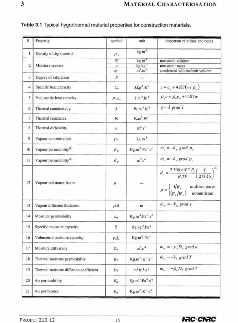
PAGETABLE 3.1 TYPICAL H Y G R ~ H E R M A L MATERIAL PROPERTTES FOR C O N S T R U ~ O N MATERIALS
...
15TABLE 3.2 ESSEK~AZ HYGROTHERMAL MATERIAL PROPERTIES (AFTER HENS 1996)
...
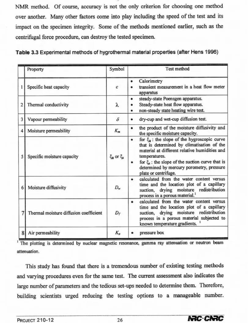
17TABLE 3.3 E X F E R F ~ A L METHODS OF HYGROTHERMAL MATERIAL PROPERTIES (AFER HENS 1996)
..
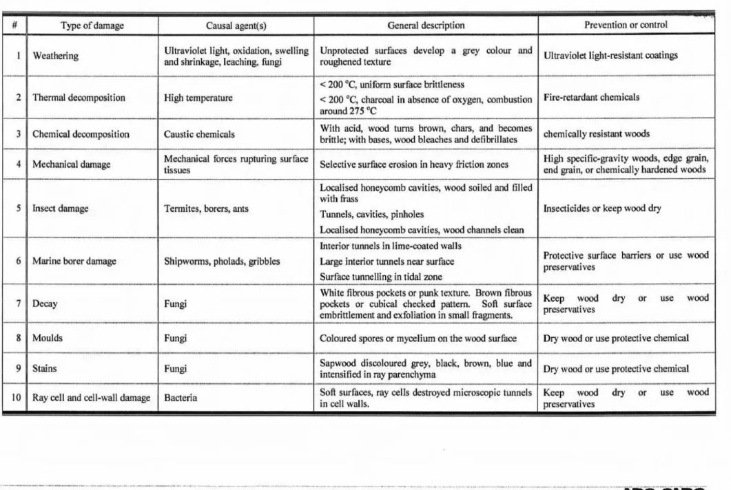
26TABLE 4.1 : OR DAMAGE TYPES M CONSTRUCTION MATERIALS WTH THEIR DESCRIPI~ON
...
36TABLE 4.2 DAMAGE CMTERIAOF ENVELOPE SERWCEABILZTY, FUNCTIONJ~LITY AND APPEARANCE
...
37TABLE 5.1 MNOR DAMAGE TYPES WCLIRF3NG IN WOOD (AFTER -EL AND MOMELL 1992)
...
44T m ~ e 5.2 MINIMUM MOISTURE LEVELS FOR DECAY DEVELOPMENT
...
...
...
53TABLE 5.3 O P ~ ~ M A L TEMPERATURE FOR COMMON WWWDECAY FUNGI
...
58TABLE 5 -4 TYPICAL EUROPEAN COLONISIWG MOULD AND STAIN FUNGI
... .
.
.
.
.
...
63TABLE 5.5 C O E F F I C I ~ TO BE USED M EQUATION [5.173
...
...
...
64TABLE 5.6 OPTIMAL TEMPERATURE FOR COMMON HARMFUL WOODDECAY FUNGI IN EWRPE
...
69TABLE 5.7 TYPICAL VALUES OF VARIOUS STRENGTH LOSSES I%)
...
@ROW-ROT FUNGI)...
71TABLE 5.8 TYPICAL VALUES OF VARIOUS STRENGTH LOSSES (D/b)
...
(WHITE-ROT FLWGI)...
72TABLE 5.9 COEFFICIENTS TO BE WED M EQUATION [5
.
191...
73TABLE 5.1 0 OPTIMAL TEMPERATURE FOR COMMON WOOPDECAY FUNGI
...
.
.
.
.
...
58TABLE 7.1 CAPILLARY P D R O S ~ ~ Y AS A FUNCTION OF THE ORIGINAL W A ~ C E M E N T RATIO
...
81TABLE 7.2 DAMAGE SOURCES AND TRIGGERING LOADS IN CONCRETE MAERFALS
...
89TABLE 7.3 SCALES DEFINITION A ~ R TO DTHE ~SEE REPRESENTATIVE VOLUME ELEMENT (RVE)
....
92....
~ G U R E
...
..- ... ... ..-.. ....
.-I.
...
wMw... ...
--
I...
PACEFIGURE 3.1 TYPICAL SORFTION ISOTHERM OF COMMON POROUS BUILDING MATERIALS
...
I 6FIGURE 3.2 SCHEMATIC AND PHOTOGRAPHIC VIEWS OF LAYOUT PRESSURE VESEL
...
..,..
.
20FIGURE 3.3 TEST SET-UP FOR DRYCUP AND W < W P MEASUREMENTS
...
... 2 1 FIGURE 3.4 E X P E ~ D EXPERIMENTAL RESULTS FOR (A) PION-WGROSCQPIC AND (3)...
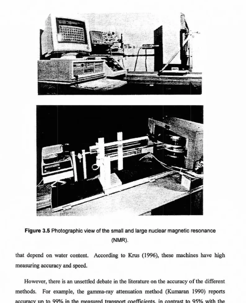
,.22FIGURE 3.5 ~IOTOGRAPHIC VIEW OF THE SMALL ANI3 LARGE NUCLEAR MAGNETIC RESONANCE (NhfR)
.
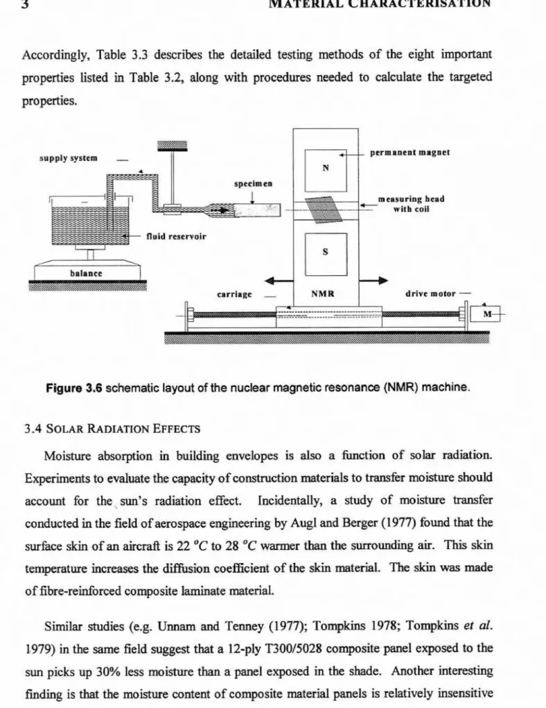
25 FFGURE 3.6 SCHEMATIC LAYOUT OF THE NUCLEAR MAGNEnC RESONANCEm)
MACHRE...
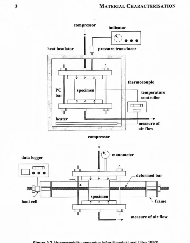
27FIGURE 3.7 AIR PERMEABILITY APPARATUS ( A F E R NAGATAKI AND UJIKE 1
m)
...
29FIGURE 5.1 MOISTURE CONTENT FACTOR FOR DAMAGE MODEL
... ,.
..
...
50FIGURE 5.2 ~ P I C A L MOISTURE CONTENTS FOR OBTIMAL FLINGPIS GROWTH
...
53...
FIGURE 5.3 TYPICAL GROWFA RESWNSE OF TWES VERSICIOLORGAITER
SCHEFFER 1986) 54 Figure 5.4 Combined effects of oxygen and c m b dioxide on product decay rate...
55...
FIGURE 5.5 COMBWED EFFECTS OF OXYGEN AND CARBON DIOXIDE OM GROWTH OF..
56FIGURE 5.6 TYPICAL GROWTH CURVE OF MESOPHILIC W00D-INWWlTING FUNGUS
...
57...
FIGURE 5.7 ~ R Q X I M A T E G R ORANGES ~ OF THREE W O O P ~ N I - W B ~ G FUNGI 58...
FIGURE 5.8 CHANGES WNlTROGEN CONTENT DURTNG VARIOUS GROWTH STAGES OF FUNGUS 59...
....
FEURE 5.9 TEMPERATURE EFFECT ON WOOD DAMAGE DUE TO MOULPRECAY GROWH.
.
64...
FIGURE 5.10 EFFECTS OF THE (A] WOOD SURFACE QUALITY AND (3) WOOD SPECIES ON...
65FIGURE 5
.
I 1 DAMAGE AT DIFFERENT STAGES OF G R O...
~ 66F~GURE 5.12 FUNGAL GROWTH UNDER F L W A T I N G RELATIVE HUMIDlTY
...
68...
FIG~~RE~.~~APPA&TTUSFOR Y A C ~ ~ R E G N A ~ . O N F O R A S T M T E ~ T ~ D Dl413-76 TO FIGURE 5.14 DAMAGE EX VARIATION (AFTER N A V A N D ~ A.ND ELMARSSON 199 1)...
75...
FIGURE 7.1 POSSIBLE VARIATION IN HYGROTHERMAL PROPEKT~ES. 90 a FIGURE 7.2 C O N ~ E MATERIAL CORRODON PROCESS... .
.
.
.
.
...
95FIGURE 7.3 REWFORCEMENT MA- CORROSION PROCESS
...
98FIGURE 7.4 TYPICAL CORROSION PROCESS OF STEm RHMFORCEhENT W CONCRETE
...
99...
FIGURE 7.5 MODELS OF THE c CORROSION PROCESS IN REGION OF LOCALLY REDUCED AZKALINTY I QO-...
F~GURE 9.1 PROPOSED APPROACH FOR DAMAGE FUNCTIONS OF MATERIALS 3
FIGURE 9.2 TYPICAL STRESS DISTRlBUTJOEI OF A CRACKED BAR
...
105...
FIGURE 9.3 TYPICAL DEFORMATrON DUE TO CRACK 107
Moisture, temperature aud mechanical loading are the leading causes of the
continuous deterioration of
building
materials and envelopes. Concrete, wood., masonryand
steel are the traditional materials, used to construct budding envelopes. Theconstruction industry is now using new composite materials (Balaguru snd
Shah,
t 992)such as fibre or fabric-reinforced resins, to meet speci6c demands of increased load and
structure durability. However, the traditional mate&ls are stdl used
in
constructionkcause they are thought to
be
economical and available world-wide. For example,concrete structures represent more than 65% of
all
existing structures not including one- and two-storey residential buildings. Woodand
masonry materials, on the other hand,are primarily
used
in
most housing md low-rise residential m d office buildings.Most existing building stocks
in
the developed world were built over the last 40 years. A misconception that construction materials are indestructible results in an undueemphasis on construction costs rather than the lifqcle cust of buiIdings
and
theirenvelopes. Consequently, these m c t m ofla experience deterioration and distress
after onIy 10 years of service. The envelope may continue to
be
serviceable for a Ionger periad, but its durability remainsan
issue of economics. Damage prevention of buildingenveIopcs is the most cost-effective measure, compared to repair or replacement of the whok structure. However, in some instances, regulatory agencies are concerned with
taxes or historical signifcanee. Therefore, govermnent s and stakeholders sometimes require costly rehabilitation
and
upgrading measures for these building stocks. Thesemeasures usually ficus on upgrading the safety of these structures and improving their
indoor environments and exterior aesthetics,
A recent study by the Natiod Materials Advisory Board (BMAB) of the National Research Council
i
n
the United States (ACIE
988) has found a problem with inadequatedurability of structures. The study estimates that the current value of concrete infrastructure ahne in the United States
is
at least $6 triUion, and that repairand
replacement costs could well reach between $1 and
$3
trillion dollars over the nextf
5years.
The
c a m s of inadequate durability areidentified
as both technical andinstitutiod.
On the technical side, the study found "inadequate knowledge of the mechanisms of development,
and
subsequent degrdation, of concrete propertiesn, as well as difficultyin
"assessing the present condition and remaining service life of concrete strtcchrres".Among the recommendations made by the bard to ameliorate the situation is to "develop in-depth understanding of the manner in which the compsitiorr and micrusmcfure of materials @ect
their
pejbmance".Among institutional issues, the report called for "the development of a proper
howledge-based expert system for providing the rules for producing durable concrete".
This conclusion is valid not ody
h r
conmete, but also for d other comtmctiwn and newmaterials. The board im this regard concIuded that "at present, only limited iqftormation is avuilable on predictirrg the long-term bekiwiour of a building material or s t m i w e in a spec$c environment, and even less is normal# made use of". The b o d recommended
the development of such a system to predict the service life of construction materials. It
wouId contain a mathematical model to document the observed degradation, to compare the data with past experience and test da@ and to pamit cdculatbn of the acceleration
The observations, concIusions and recommendations o f this distinguished board do
not apply only to the United States; but also wrldwide, including Canada. It m y
be
argued that the hdhtructure in Canada is in better shape than that
in
the United States.If this is so, then it is due more to the hstitutioml policies
and
the
younger age of thestructures iu Canada than to superior techGcaI know-how.
Clearly, the problem of durability is mt just due to over-stresing of stnrctuaes; a
whole range
of
physio-chemicaland
mechanical processes, as well as improper designand practices,
are
responsible for building envelope deterioration. The ability ~fconstruction materials to transfer loads without experiencing distress depends on the
nature and magnitude of the applied stresses, moistwe contents, and structure
temperatures.
Moisture,
temperatw, and stress, as we11 as damage distribution of the materials, are also functions af the microstGucture of wmtmetion materials. The amountof moisture retained by the structure envelopes is also a function of the surrounding
environmental conditions. In general, environmental conditions include
all
possible chemical, physical and mechanical influences.With all these complex issues, present design
and
rehabilitation practices still rely heavilyon
essentiaIly a single macroscopic property. For example, in the case ofconcrete and masomy, the campressive cylinder or cubic strength is often used 10 design
the whole
structure.
For wood mtwials, designersand
architectsuse
available empirical equations (Kenneth et 01. 1992; Gerhards 1988; Gerhards and Link 1987)ns
well asexperience to design and rehabilitate the residential dwellings.
The cummt practices uncouple the mechanical
and
hygrothermal fields to solve the governing tramport and deformation equations. Traditionally, the hygrothed analysisis conducted
firsz
to estimate the moistureand
temperature distributionin
the stmcttrraI enveIope. The advancesin
the area of computatioml fluid dynamics in buiIdEng science made it possible to estimate moistureand
temperature distribution for most buildingdamage. Therefore, the resulting moisture and thermal loading are applied as loads to
obtain stresses and deformation of the structure. These defbrmations are predicted using elasticity or plasticity
thwries (Sih
et a!. 1986;ShYaike
and
Karagiozis 1997).The drawback of this solution strategy is that the elasticity
and
plasticity theoriesassume materials are homogenous
and
continuous. Therefore, until recently, models based on these theories have %led to identify adequately the behaviour sf damagedbrittle materials. Since brittIe materials b c t u r e under loading, it was d s e d t b t the
relationship between the fracture energy wd the energy produced by the applied stresses
is the key to u n d m t m d i i the micro-mechanics of concrete (Kunin 1983; Mindless 1983;
Zaitsev 1983).
The propagation of cracks in construction materials is governed by the activation energy for kc-.
This
h c t w energy is the specific energy required to he& bondsand to create surfaces
and
spacesin
the material volume. This failure lnechaaisrnrepresents the characteristics of a brittle material versus a ductile materid. With the exception of metals, all construction materials are heterogeneous brittle solids, interspersed with
m
y
voidsand
defects. The moistureand
temperaturein
and m u dthese defect volumes also affect their evoIution and propagation. Thus, the key to understanding the micro-mechanics
and
hygrothmnd khaviom of constructionmaterials is the manner in which h&we energy
is
related to the energy produced by theapplied mechanical, moisture, and thermal loads.
Classicd hcture mechanics was originally developed to describe the behaviour of discrete macroscopic cracks,
but
its adaptation to an emmble of randomly distributed microcracks is a relatively new development (NoEd 1997). This new area of mwanics is referred to as continuum damage nnechanics(CIDh4).
The development
of
CDM aims to explain thelink
between the microscopic processesprocess involves initiation, evolution, and propagation of cracks in the damaged material
undw
the influence of dserent stress fields.Physical observations indicate that deterioration and undesirable deformations are in
many instances, not due only to mechanical overloading, but are also the results of excessive moistwe and temperature fluctuafion, Observed deterioration
in
hot climates seems to be different from the effects in cold climates. For example, structure envelopes in hot countries often lose their externaI cladding tiles and coating after short periods.In
cold climates, building envelopes experience the freeze-thaw cycIe effects. Erosion of facades, pauels and veneer wdh due to wind-driven rain is dso a common problem f i r
buildings in both climate conditions. However, special coatings rrray provide protection
against the latter effect, as welt as against ultraviolet radiation. Therefore, varying Ioads, absorbed moisture, and temperature changes causes d e t e r i ~ r a t i ~ ~ Hygrothemd and mechanical loading continue to degrade the physical, f h e d and mechanical properties of the material. Accordingfy, structure melopes subjected to any combination of these
loads d l not live their full design life. Thus, improvements in the analysis, design
and
damrage predictions of materials
and
structures can have great economic andlor safetyimplications.
Moisture and t h m l damage of building envelopes
is
often intensifiedif the
moisture carries cornding substances such as sodium cHoride or calchm chloride. The
cornding agent suspended in the moisture attacks the reinforcing, studs, and fastening metal m a t d s . The chemical reaction between the chloride ions and the metal material
causes the corrosion of these mterials and oxygen and tempmdture often accelerates the comsion processes.
The
chemical reaction decreases the metal material volume; hence,cornsion causes mere damage a n d may even muIt
in
failure of the strudmd elements.The severity of the comsion depends on the number
of
poses and defects that facilitateCustomary building materials, with the exception of steel, are naturally prow. The
distribution of the pres
and
defects causes flumtion in the moisture md temperature fields within the rnaterial structure. Thus, s w a g e , creep, rot, and thermal-induced stxesses are developedwithout the
presence of any mechanical Ioadimg.In
some instances, these strains are large enough,and
occur in such mitical places, that themteriab becomes damaged and cracked, Adequate understanding of the durability o f
the construction materials is necessary to avoid expensive rehabilitation, or demolishing the entire
building.
Construction materials are non-homogeneous composites composed of different materials. For example, concrete materials comprise cement, water, fine and coarse
aggregates, air (voids), sometimes and other chemical admkhms. Similarly, mod, rock,
and clay-brick materials contain mtwd organic chemical, flaws, faults, and some
discontinuities. The incompatible mechanica1, hygroscopic and t h d properties of the different m a t a d s within the mimstructure are the underlying c a w s of the micro-
cracks h t exist at the microstructure level of construction materials. The presence and propagation
of
the cracks under applied stresses is lone of the principal mechanisms that determine the behaviour and strength of these materiaIs (e.g. Mmdess 1983; Zaitsev1983; Horii and Nemat-Nasser 1985; 1986).
Moistwe in these cracks and temperature fluctuation can often increase the rate of damage
of
these materials, reduce the life span of the structureand
diminish its durability. However, exposure to certain environmental conditions can a h provide h u m b l e temperatures and moisture that enhance durability.It
k
also usefir1
to identifythese conditions,
in
order to design smart structure envelopes.1.6 OBJECTR~ES AND SCOPE
The
principaI objedive of this report is to d e w the literature concerned with durability and hygrothermal performance and damage of materials. Italso
presents anovel approach for measuring and modelling damage in the different construction
materials
and
buiIding envelopes.This report spechifically summarises the experimental and analytical work conducted
aver the
last
20 years. 'Fhe merit study outlines the lessons learnedh m
the reviewedinvestigations. This report also identifies areas
in
the field of structural and materialdurability experiments that need kther studies
and
require more physical testing.Existing durability testing
a d
damage assessment procedures are critically discussed, and modifications are pmposedin
order to use their result efficiently. SpecificdIy, thecurrent work focuses on:
(11 experimental studies of durabiIity conducted over the
lasZ
20 years;[2] the types of damage associated with various construction materials;
131 the different testing philoosophies
used
to identify damage associated withhygrothmI loading;
[4] the damage models developed h m experiments;
151 the proposal of research areas to be conducted by the National Research Council of Canada to develop leadership
in
this important area; and161 the proposal of a novel approach for modelling and measuring hygrotheml damage
of
building materialsand
envelopes.1.7
REPORT
STRUCTUREChapter 2 d s e s the theoretical h i s of the mechanics of moisture and heat lmnsfkr in construction materiaI. All theoretical models of durability
and
hygrothmd assessment require physical, chemical, and mechanical properties. Therefire, Chapter 3discusses the experimental work on the material characterisation. Chapter 3 also addrases experiments aimed at predicting the behaviow of comtmctioln materials in the
humidity and extreme temperatures are used. Thus, moisture contents far exceed actual
conditions,
and
damage estimates based on the results of these tests wouldlead
to over- designed componentsof
building envelopes. The researcher has tobe
aware of theconsequences
of
this approach.It is important ta rely on data collected over 20 years because of the continuous developments of new materials. Damage estimation has to
bz
predicted h m acceleratedtests. Howwer, the actual
field
data are invaIuable and provide the exad scenario of thedamage process for given environmental conditions. Thus, Chapter 4 discusses the tests
on the performance and durability of actual buildings.
Chapters 5,6,7, and 8 describe current literature for estimating h y p t h t m l damage for wood, brick, concrete, md other materials
such
as paint and bitumen, respectively.Chapter 9 presents the novel approach of darnage that will be used to quantify damage
both
d y t i c d l yand
experimentally. The approach is basedon
measuring stfiess degradation caused by damage acmulatienas
r e d of hygmtknnal andmechanical loads. It also indicates the position of the Institute far Research in Construction (IRC), National Research Council of Canada, (NK) and identifies
areas
where more research is needed. Chapter 10 also d s e s the conclusions and some recommendations based on the Iinding of the cmmt study.
Finally, the report ends by providing the list of references cited in the different chapters.
M E C H A N I C S
O F
T H E
H Y G R O T H E R M A L
P R O B L E M
2.1 GENERAL
To
conduct useful hygrothermal testing, it is important to understand the unda1yingprocesses. The aim of envimnmental testing is to evaluate the physical behaviour of
construction materials under changing conditions. Experimental results also provide means of enhancing
and
calibrating the prediction capaliilities of the theoretical models. Therefore, summarising the theoretica1 basis for heat, air and moisture transport d l provide a unified criterion to assess the different experiments procedures.The
axioms of conservation of energy, mass and momentum govern the behaviour ofany fluid lor solid continuum,:
I. the mass balance or continuity condition
2. the thermal energy balance
a
- I p e d v + ~ ( V - V , ) - ~ ] & -
I(g:
gmd v + h ) d v = 0 ; and2
MECHANICS
OFTHE
HYGROTAERMAL
PROBLEM
3. the momentum balance or Cauchy's fust law of mat ion
These equations are valid for any arbitrary part of the continuum of volume V
bounded by the
surface
S with surface wdordS
pointing outwards.In
these equations,p is the density, v is the continuum veIocity vector, v, is the srrrface vebcity, e
is
thespecific internal energy, q is the heat flux, and h
is
the internal energy heat source.On
the other h d , a is the stress tensor,
and
f
is the resultant body hrce. t represents time ofthe
incideat(s). The symbol @ indicates the cross productof
two vectors ortensors.
When moving boundaries bound the continuum, the additional space conservation
law should
be used in
conjunction with the conservation equations.These equations are sufficient
and
necessary to describe the ovmd be'fiaviou of thecontinuum.
Moisture absorption in porous materials under temperature gradient occurs by
different mechanisms. Cracks and voids in the material space provide one of those
mechanisms (NoM 1997). Philip and De Vries (1957) established the. mathematical formulations of m s transfer at the macroscopic level
in
poreus materid Whitaker(1977) and Bear and & k t (1990) later Introduced a more fundamental solution of
the diffusion equation in porous materials. When layers of various materials used to
tom
the building envelopes, moisture escapesand
transfers though the gaps and intehcesamong layers. The moisture
in
porous materials canbe
present in any form of the solid, liquid or gas phases (e-g. Hens 1996; Hokoi and Kumran 2 993; C m f i e t et al. 1995, etc.).MECHANICS
OFTHE
~ Y G R O T H E R M A LPROBLEM
For simultaneous heat, air and moisture actiom, 0nsager7s principle of the irreversible process of thermodynamics may be applied (Hens 1996; Duforestel
1993;
and
Luikov 1966). The Onsager's principle states that eachflux
within porous m t b l s is representedby
a linear combination of gradients of driving forces, i.e.represents the deriving forces of state j
.
Subscript x signifies the different air, moisture and ice flux modes. Note that repeated indicesin
Equation (T2.51 mean summations. Thcrcfore, the coefficients, C,,
define nine macroscopic transport tensors,describing
the
permeability properties of the porous materid For example, the expandedform of equation
12-51
to describe the moistureflux
will be of the following format:The change in mass can be stated as
x
am
ap,
b x +___e x - -I--- h x * - , L + q - + B r n q F ap ?Pz *3
%I at
at
P-TI
at ap,
a
?Pa atw3
and
the enthalpy content may be found byIn
equations [2.7and
12-81, the symbol x stands for either air, water, vapour, ice ormoisture. The coefficients B, I charactrise the storage capabilities of the
pornus
medium per unit change of deriving force. They are called specific capacities.
n e s e coefficients depend
on
temperature, stored mass and B,.
The parameters, =iB'
s are mre important t bothers. Thus, material characterisation experiments dependon the considered materid under testing. This issue is discussed
in
the next chapter.Inserting the flux of equations
12.51
and tfke capacity definitions of equations 12.71 and f2.81 into the mass energy balance equationsp.l]
and[2.2] yields:
for heat
for moisture
These equations. represent three partial differential equations defining:
(3
9 specific capacities; (ii) 9 transfer tensors;and
(iii) 3 source terms, S,,
S,
and
$,.
All
these quantities are firnctions of the three driving forces. Some of them also depend on the stored quantities and on time.ab
analyse the hygrotheml behaviour of a building envelope ushg these subsets of equations, the 18 coefficients and tensors have tobe
known for each material used in theenvelope.
In
addition, thethree
s o m e terms mstbe
defined ExampIa of s o m termsare hydration
and
dryingof
concrete, carbonisation of lime-plaster, salt crystallisation, evaporationand
hezing of liquid, The solution of equations L2.91 to 12.1 13 requires also the complete description of the geometryand
composition of the envelope.In
addition, the analyst must define the contact conditions among layers and the initEal condition, andMECHANICS
OF TEEHYGROTHERMAL
PROBLEM
thermal
and
physical material properties mustbe
identilied in order to use these equations.Finally, it should be
pointed out that the useof
these equations to evaluate the hhayiourof
corrzpEexbuilding
envelopes requires numerical technique, Finitediierence, k i t e element
and
control volume methods are d y used to solve these equations.2.3 DISCUSSION
The brief discussion of the mechanics of the problem
in
section 2.2 illustrates the degree of complexity of moisture and heat m f e rin
materials. Therefore, bddingphysicists and researchers focused on solving the tramport problem for prous materials used
in
constructions. Almostdl
hygrothermal models, exceptions inelude Demirdzicand Mwaferija (1994),
and
Sih et 01. (19863, ignore the momentum equationsin
deriving the materials constitutive relationships. The season for dropping the conservation ofmomentum requhments is that mass flow does not generate large velocities. Large velocities occur only in the
case
of air movements through leaksand
cavities as well asThe use of computer-based models to trace
the
perfbnrmnce of materials subjected tothem1 and moisture loading has been on the rise ever the past 10 years (Hens 1996). Even the Teast sophisticated procedures o f these computer models require many material. data input parameters. The success
of
any of these computer models alsodepends
on theboundary conditions specified for a given simulation. According to the conservation
and
flow equations discussed
in
Chapter 2, 18 coefficientsand
transfer tensors areneeded.
The coefficients are either merial properties or m f e r capacities, depending on their
usage
in
those equations.This chapter discusses the necessary material properties, specific capacities, and
trans* tensors o f combuctien materials.
In
the following subsections, the test procedurefor each property or item will be discussed. The presentation also shows the ad-ges of some of these testing methods. Possible enhancements of these methods are aIso indicated.
3.2 MATERIAL PROPERTIES
A
full
computer model(Hem
1996) requires about 21 m a t d properties to definemoisture
and
heat storage characteics. The hygroscopic and physical properties listedin
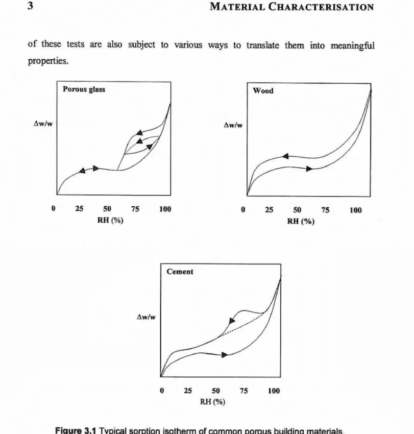
Table 3.1 are necessary for any construction material characterisationTo
quantifyof these tests are also subject to ~ u u s ways to translate them
into
meaningfilproperties.
Pomns glass
0 25 50 75 100
RH (Yo)
Figure 3.1 Typical sorption isotherm of common porous building mateflak.
In
ream, according to Kumaran (1 9963, the total number of material parameters is 9 fphysical quantities. However, Table 3.1 shows that some of the 21 hygroscopic material
parameters are related. For example, Hokoi
and
Kummm (1 993) stated thatthe
moisturem, vapour pressure pv
and
temperature T, are dependenton
one another, and that one ofmaking
use
of a suction pressure curve or sorption isotherm. Figure 3.1 shows typicalcurves for three building materials.
These m e s explain the variation in behaviour of diEwent constmction materials,
One important ohnation is
that
the adsorption (wetting)and
desorption (drying) curvesare not the same. These curves are aka different -for different materials. Figure 3.1
also
indicates that between the dry and hIIy saturated states, the moisture contents vary
nonlinearly (Kumaran 1996).
However,
Hem
(196) indicatedthat
there is agreement among building physicists that the w i r e dmeasured
nmterid parameters shouIdbe
the minimum number.Thus,
Hens (1 996)and
Kumaran (1 996) suggested the measurement of only eight important properties. The rest of these properties maybe
estimatedby
manipulating certain testresults (Kumararm 1996)- This approximation will affect the quality of the predicted behaviour of any computer model.
In
my caseF resarchers must interpret the numeric results cautiously. The significant material properties are those listedin
Table 3.2,together with the main functional dependence.
Ta b k
3.2
Essential hygrothermal material properties (After Hens 1996)I
1I
Specific heat capecityI
T e m p m a w moisture content t h e and heat
I
l f l OW d i d o n3 VapwpermeabIlity Temperature, moisture content and rapour flow
-
-4 Moisture permeability Km Temperature, moishrre flow direction content and moisture
I
I
or &I
Tempera- snd m o i h m contentI
Moisture diffirsivity
1
T e m p t u r q direction moisture cmmt and yapour flow7 8
ahermal moisture &&ion ~ E c i e n t air permeability
Dr
''
temperature, moisture contmt and moisture flow direction
temperature, moisture cuntent and air flow direction
Therefibre, the number of experiments to determine these essential parameters needed to become manageable. These tests are discussed
in
the following section.It was stated earlier that some of the hygroscopic properties of construction materials
are w-dependent and interdependent. Therefore, resuJts of different experiments can
be
combined and used to estimate the rest of the material properties. The literature contains a variety of markedly different procedures to evaluate the storage characteristics, moisture
and
temperature transport and vapour diffusion coefficientsof
these materiaIs. According tokms
( I 996) and Kummm (1 997), someof
these test methods are not well suited for meamkg these properties. The testing procedures wn be performed on aporous material to determine:
(I) its storage characteristics;
(2) its vapour d i i i o n coefficients;
(3) Its capillary transport coefficients; and (4)
air
transportA brief discussion of these test procedures folIows h the subsequent sections- The
merit of each test is investigated, as well as its use
in
measuring the specified material propertyand
hygrothermal parameters.It is universally accepted that to d e t d e the storage characteristics of a budding
material, the sorption mistwe and capiIIary regions must be separated. In the sorption
moisture region, the following sirnpIe procedure is o f h used.
The specimen is placed
in
m mviromentaIly regulated chamber using salt soIutionvarying in stages fism less than 50% up to 90%
RH
produces
the absorptionisathem The reverse of the process
yields
thedesorption isotherm.
Knrs
(1996)indicated that measurements above 95% RH should
not
be made becausethe
sorption isotheran fbr hygroscopic building materialsis
extremely steep.His
remark was basedon
the recommendation of DIN 5261 5. This specification states that small unavoidable
variations in the relative humidity by themselves cause very large changes
in
s o w o nmoisture. Small variations can be the remit
of
slight variationin
the temperatuse of the specimen Another drawback of this testing methodology is that7 depending on the tested material the test may take several weeks to conclude.F a g e r l d (1 977) proposed
an
alternative procedure, in which the f k e z h g point of waterin
pores of decreasingradius
is lowered. The lowering o f the hezing pointproduces a relatiemhip between the hezing point depression, the
radius
of pores, andthe Kelvin equation
(Harmathy
1967) with relative humidity. The testingtime is
for thismethod is reduced to 3 hours. However, the k e z h g can cause stmctud
damage
to thespecimen. Furthermore, the measuring
and
recording equipment involved are relativelylarge.
In
the crtpiIIary water region, the storage function representing the relationshipbetween the capillary pressure and water content can be determined from mercury pornshetry,
In
all testing procedures, capillary or suction presswe is controlled, and water content determined after estabfishment of quil~ibrium. The suction pressme c w eis obtained by incremental increases in the suction pressure. The water
is
removed h m the specimen using centrifugal force or pressure applied directly to the liquid in the pore space. Osmotic phenomena (Croney d al, 1952) are used to buiId the measuring equipment.One limitation of
this
test methodis
that the appIied centrifugal force can destroy thespecimen though higher macbnicd stresses. The method, moreover, is relatively expensive. The moisture profile has to be determined quickly and immediately after the
latter problem is avoided
by
using relatively smaller specimens with very t k e pores. Themjar drawback of the
method
isthe
very
limited
suction pressure range (0 toI
bar)used. The suction presswe range can
be
increased significantly ifthe
pressure plateapparatus of Gardnm (1956) is wed.
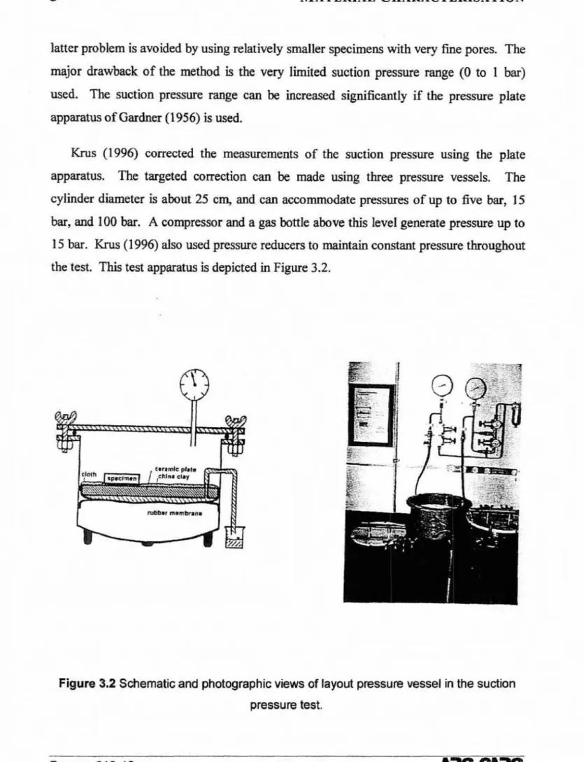
h s (1996) corrected the measurements of the suction pressure using the plate apparatus. The targeted correction can be made wing three pressure vessels.
The
cylinder diameter
is
about 25 cm, and can accommodate presmm of up to i k e bar, 15bar,
and I00bar.
A compressorand
a gas bottIeabove
this level generate p mup
to15
bar.
Krus (1996) alsoused
pressure reducers to maintain constant pressure throughoutthe test This test appasatus
is
depicted in Figure 3.2.Figure 3.2 Schematic and photographic views
of
layout pressut~ vessel in the suction pressure test.The measurements
of
vapour W s i o n caefficients are standardbedin
Imfi ASTMstandard test
method E96
(1989)
and DIN 5261 5 1( 1987).The
tests are universallyknown
as the 44dry-cup" and "wet-cupv' methods ( K m a n 1997; Krus 1996). The dry-cup
measurement evaluates the diffusion coefficients
in
the moisture region fiom 0% and 50%FbI.
The wet-cup test traces the sam meficientsin
the 50% to 100% moistureregion.
The
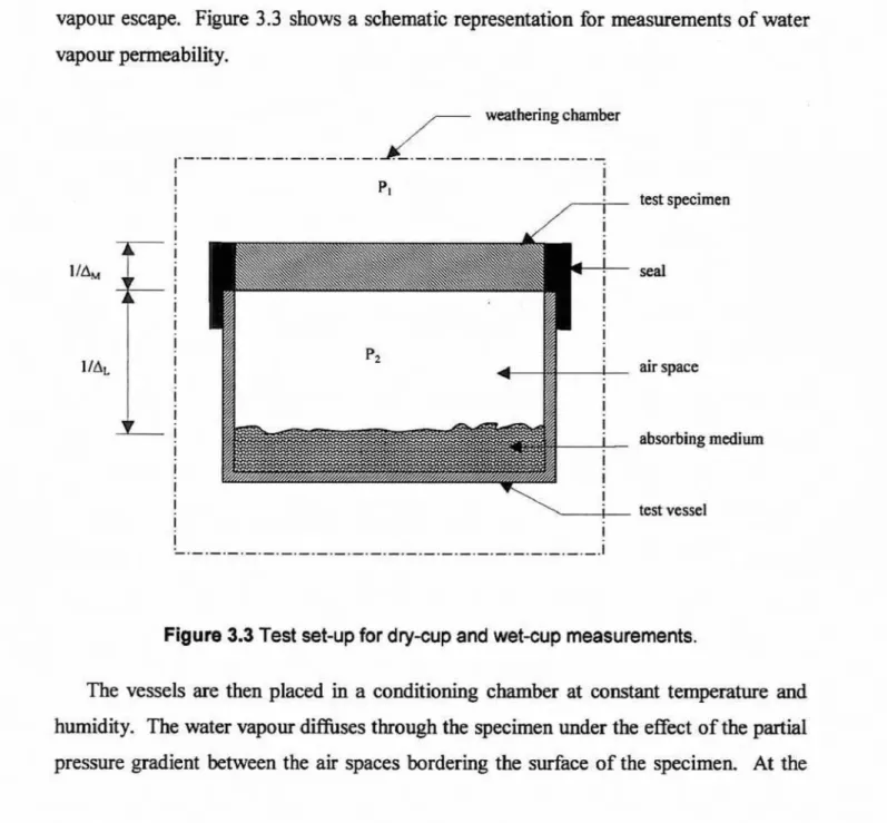
test set-up consists of placing a pIate-shaped specimen of the materia1 underinvestigation atop a vessel as its cover. The edges
of
the vessel are airtight to prevent vapour escape. Figure 3 -3 shows a schematic representation for measurements of water vapour permeability.,'--
weathering chamber air space abmrbing medim I I test vessel I ! L---.---.-.-*-.-~-.-.-*-~d.~~~.-.-.-.d.-.4.d.lFigure 3.3 Test set-up for dy-cup and wet-cup measurements.
The vessels sre then placed
in
a conditioning chamber at constant tempatweand
humidity. The wata vapour diffuses through the specimen under the effect of the partial
onset of steady flow diffusion, the test vessel weight undergoes constant changes with respect to unit of time,
For thin layers of non-hygroscopic materials, the stationary diffusion flow is
established almost at once, without the start-up process. However, moisture equfi'brium
from the ambient exterior and interior conditions must be established for thicker layers of hygroscopic materials. It should be mentioned that the initial weight changes of the tes vessel, including the test specimen are attributable to changes
in
moisture of the testspecimen, and to weight changes
in
the sorbnt inside the vessel. Knrs (1995) indicatedthat there are methods ~r avercoming this shortcoming by weighing the test specimen
and the sorbent separately.
Figure 3.4 Expected experimental
results for
(a) non-hygroscopic and (b) hygroscopic materials.A layer of
air
between the underside of the specimenand
the clfying agent solution is c u s t o d y used This space is included to prevent wetting the specimen undersidestagnant air exists. The air space does not affect the measurements
in
the caseof
drycup,but it has remarkable impact h the wet-cup method. The sensitivity of the measurements in the Iatter case
is
especially criticalhr
specimens with low diffiuion resistance.K m m (1 997) introduced an extension to this method where
he
applied it wing varying relative h m i d ' i levels outside the cup. HeaEso proposed
a relationship tosmooth the experimental results to match the typica1 graphs given in Figure 3.4 fbr non-
hypscopic and hygroscopic material~. The permeance of the test assembly according to
Kumaran (1
997)
may read asmagnitude of the derivative
pamcanoe
(RH?)=
x IOQSaturation water v a p pressure at 23 'C
Kurmaran (1997) dm w e s t e d correcting these values accord'ig to the procedures described by Lackey ef a/.
(1997)
and Hanseaand
LuncE (1990). These correctionsaccount for the d c e resistance and the resistance offered by the still air inside the cup. The corrected permeance, multipfid by
the
average thicknessof
the material, gives the permeability of the material at any givenW h .
Knls (1996) also described a siEniIar1yelaborate procedure. The miin difference between the two approaches is only
in
the homogenisation process. The work of Krus (1 99m uses the following Kelvin equation, derived by KiebI(1996).2scosO
relative humidity
(RH%)
=)
~ P W R D T
where the symbol o ( N / m ) stands for the
surface
temion of water, 0(degree)
is thewetting angle, r ( m ) is the capiIlary radius,
RD
( J / k g m K ) is the gm eonstant, p,( kg/m3 ) is the density of the water, and