Publisher’s version / Version de l'éditeur:
Vous avez des questions? Nous pouvons vous aider. Pour communiquer directement avec un auteur, consultez la première page de la revue dans laquelle son article a été publié afin de trouver ses coordonnées. Si vous n’arrivez pas à les repérer, communiquez avec nous à PublicationsArchive-ArchivesPublications@nrc-cnrc.gc.ca.
Questions? Contact the NRC Publications Archive team at
PublicationsArchive-ArchivesPublications@nrc-cnrc.gc.ca. If you wish to email the authors directly, please see the first page of the publication for their contact information.
https://publications-cnrc.canada.ca/fra/droits
L’accès à ce site Web et l’utilisation de son contenu sont assujettis aux conditions présentées dans le site
LISEZ CES CONDITIONS ATTENTIVEMENT AVANT D’UTILISER CE SITE WEB.
Paper (National Research Council of Canada. Institute for Research in
Construction), 1990
READ THESE TERMS AND CONDITIONS CAREFULLY BEFORE USING THIS WEBSITE. https://nrc-publications.canada.ca/eng/copyright
NRC Publications Archive Record / Notice des Archives des publications du CNRC :
https://nrc-publications.canada.ca/eng/view/object/?id=784ee9ea-3e52-4883-8178-9792b01ead85
https://publications-cnrc.canada.ca/fra/voir/objet/?id=784ee9ea-3e52-4883-8178-9792b01ead85
NRC Publications Archive
Archives des publications du CNRC
This publication could be one of several versions: author’s original, accepted manuscript or the publisher’s version. / La version de cette publication peut être l’une des suivantes : la version prépublication de l’auteur, la version acceptée du manuscrit ou la version de l’éditeur.
For the publisher’s version, please access the DOI link below./ Pour consulter la version de l’éditeur, utilisez le lien DOI ci-dessous.
https://doi.org/10.4224/40001382
Access and use of this website and the material on it are subject to the Terms and Conditions set forth at
A study of the effect of the tank diameter on the thermal stratification in
LPG tanks subjected to fire engulfment
S e r
T H 1
National Research
Conseil national
N 2 1 d
1+1
Council Canada
de
recherches Canada
1 6 9 6
i 9 9 0
Institute for
lnstitut de
BLDG.
Research in
Construction
construction
recherche en
- - - -mc-cm
A Study of
the
Effect of
the
Tank
Diameter on
the
Thermal
Stratification
in LPG
Tanks
Subjected to Fire Engulfment
by G.V. Hadjisophocleous, A.C.M. Sousa and
J.E.S.
Venart
ANALYZED
Reprinted from
Journal of Hazardous Materials
Vol. 25, 1990
pp. 1431
(IRC Paper No. 1696)
NRCC 32366
--=an
I R C
-+'L l B R A R Y
2
JUN4
1IPNBIBLIOI rlEQUE
I R C
mAE.rent - - -Canad3
Ce document decrit un modele mathematique servant
B
etudier le
comportement des reservoirs de
gaz
de petrole liquefie expods au feu. Ce
mod&le consiste en
un
certain nombre de sous-modeles de champ et de zone
qui sont utilises pour simuler les divers phenomenes physiques qui se
produisent au cours de la periode d'enveloppement du r h r v o i r par le feu.
Pour vQifier le modUe, les auteurs comparent les rbsultats prbvus avec
ceuxdes exp6riences en vraie grandeur obtenus par le Health and Safety Executive,
au Royaume-Uni (r6f.l). Les comparaisons r6vUent que le modele permet de
prevoir exactement la pression du reservoir et le delai d'ouverture de la
premiere soupape. Ce modele sert
Betudier l'effet du diametre du reservoir
sur la stratification thermique dans la region liquide.
Journal of Hazardom Materials, 25 (1990) 19-31 Elsevier Science Publishers B.V., Amsterdam
A STUDY OF THE EFFECT OF THE TANK DIAMETER ON THE THERMAL STRATIFICATION IN LPG TANKS SUBJECTED TO FIRE ENGULFMENT
1 2
G.V. Hadjisophocleous , A.C.M. Sousa and J.E.S. Venart 3
~ e s e a r c h Associate at the National Fire Laboratory, Institute for Research in Construction, Watiollal Rese.uch Council of Canada
2~rofessor at the Department of Mechanical Enginecring, University of New Brunswick, Fredericton New Brunswick.
3 ~ i r e c t o r of the Fire Science Centre and Professor at the Department of Mechanical Engineering, University of New Brunswick, Fredericton, New Brunswick.
ABSTRACT
This paper describes a matlternatical model developed to study the behaviour of LPG tanks when subjected to fire conditio~ls. The model consists of a number offield and zone sub- models which are used to sinzulate the various physicalpherwmena taking place during the tank etigulfment period. 7'0 verify the model, predicted results are compared with full scale experimental data obtained by fhe Health and Safety Executive, U.K. (ref.1). The comparisons indicate that the model cat1 ucc~iralely predict the tank pressure ~ ~ n d time to first valve opening. The model I S used lo investigate the effect of thc tank rlimeter on the t l ~ r m n l stratl@cation in the liquid YL'KlOIZ.
NOiVIENCLA'l-URE a surface absorptivity;
A area of radiation sulface zone; c specific heat capacity; E en~issive power;
F geometric configuration factor: h convective heatkansfer coefficient;
J Jacobian of coordinate transfom~ation: mdiositv: k thermal conductivity
K flan~e absorption coefficient; P non-ditnensional pressure; q heat flux;
Q heat uansfer rate; cylindrical coordinates; radius;
source ten]];
time and non-dimensional time
temperature and non-dinensional temper;lture,
non-dinlcnsional velocity components in Cartesian coordinates; contravariant velocity components;
Cartesian coordinates;
Creek letters
cx
them~al diffusivity;l
a ,
P
,y ~neiric coefticients;coefficient of thermal expansion; diffusion coefficient;
emissivity of surface; kinematic viscosity;
angle between the n o m l vector at a surface element i and the radius vector connecting surfaces i and e;
boundary fitted coordinates; density; reflectivity; S tephan-Boltzman constant; z transrnissivity; @ general variable; S u b s c r i p t s b black body; COnV C O ~ V ~ C ~ ~ O ~ A ; e fire boundary; f fire; g gas;
i tank exterior surface zone;
m weighted mean; rad radiation; t turbulent; v vapour; w wall Dill~ensionless N u m b e r s Nu Nusselt number; Pr Prandtl number, Ra Rayleigh number; Re Reynolds number. INTRODUCTION
Computer models capable of predicting the conditions in Liquefied Petroleum Gas (LPG) tanks engulfed by fire are a necessary tool to enable an understanding of the physical phenomena taking place in the tank during such incidents. This knowledge can be used to design and develop safer procedures for the storage and transportation of liquefied gases. The processes during the f i e engulfmelit period are coinplicated and interactive. Some of these processes, such as radiative and convective heat transfer from the f ~ e to the tank, radiation from the vapour-wetted wall to the liquid interface and mass discharge rate can be accurately determined using zone models. The free convective flows and heat transfer in the liquid and the vapour region during the heat up period, (up to the first valve opening), however, cannot be simulated accurately by this
mod ell in^
approach. The main reason is that these processes are not fully understood and the various zones and their interactions cannot be accurately defined, especially when dealing with partial fire engulfn~ent. Despite these limitations a number of zone models, which rely on infonnation extracted from a limited number of small and full scale experiments have been developed, (ref. 2-6). As the case simulated by a zone model deviates from the experimental scenario, this information may not be valid and its use may result in incorrect predictions.Free convectior~ can be predicted using field models, which solve the fundamental equations for conservation of continuity, momentum and energy to predict the convective flows and heat transfer in the tank. Field models, however have their own limitations as they require extensive computer time and they also rely on empirical infomlation, especially in the application of the thernlal and hydrodynamic boundary conditions at the inner tank surface. This is because the heat transfer process from the liquid wetted wall to the liquid changes with time and location. During the initial period of fire engulfment, heat is transferred by natural convection, but as the applied heat flux increases, sub-cooled boiling takes place which alters both the thermal and the hydrodynamic boundary conditions. For this reason it is not feasible, at present, to develop a field model which can simulate the total period of fire engulfnlent. Field models, however, can be used to predict the conditions in the tank during the early stages of fire engulfment and to provide infomlation, which call be fed to zone models to continue the simulation for the remaining fire engulfment period.
THE MATHEMATICAL MODEL Modellinp a i m r o a c h and a s s u m ~ t i o n a
The developed numerical model makes use of field and zone modelling approaches to simulate the LPG tank response to fue engulfment. Zone modelling is used to determine the fire heat flux applied at the tank exterior surface and the radiation heat transfer from the vapour wetted wall to the liquid interface. The heat transfer through the tank wall and the free convection in the vapour and the liquid regions are simulated using the field modelling approach.
Duc to the complexity of the problem the followirig simplifying assumptions have been made:
1. The problem is considered to be two dimensional.
2 . The Boussinesq approximation for the free convection governing equations is assumed to be valid.
3. Const:~nt effective viscosity is assumed tl~roughout the solution domain and the turbulent Prandtl number is taken as unity.
4 . Boiling at the tank walls is not cot~sidered.
5 . The interface is assumed to be waveless and static. 6 . Fire size and fire propertics are uniform.
Due to these assun~ptio~~s the model can only be used to predict the tank response during the initial period of fire engulfnlent, up to the f i s t valve openitig since, during this period, boiling is somewhat suppressed by pressurization.
The model consists of four sub-models: the fire tnodel, the wall conduction model, the vapour space radiation model and the free convection model. These sub-models are discussed in the subsequent sections.
F i r e m o w
fil Radiation heat transfer, Radiation heat transfer from the flames to the tank wall is determined following the approach used by
Birk
and Oosthuizen (ref. 7), in which the fue is assumed to occupy a rectangular space surrounding the cylindrical tank. The tank exterior surface is divided into a number of surface zones while the imaginary walls enclosing the fire are considered as a single surface zone. The radiative properties of the fire are assumed to be uniform, and its size does not change with time. The configuration factors, Fie between each..
surface zone on the tank exterior surface, Ai, and the walls enclosing the fire, Ae, are computed by numerically integrating the relation,
where R = radius vector joining the centers of the surface zones i and e; K = mean absorption coefficient of the flames, and q = angle between the normal vector at a surface element and R.
Using the configuration factors and realizing that the zones on the cylinder can only "see" part of the enclosure wall and part of the surrounding gas, the energy balance equations are written as:
where Qi= heat transfer rate; Ei = emissive power; a. = surface absorptivity, and E. = surface 1
enlissivity. The subscripts g and e stand for gas and fire enclosure respectively.
Equation (2) is solved directly to give the radiation heat flux at the various surface zones on the tank surface.
lii) Convection heat transfer, The convection heat transfer from the hot combustion gases to the tank wall is given by
qconv = h (Tw
-
TE) (3)where qconv = convection heat transfer; 11 = heat transfer coefficient; Tw = temperature at the exterior surface of the tank; and Tf = firc temperature.
The convective heat transfer coefficient, 11, is calculated based on heat transfer measurements for forced convection to cylinders in cross flow of air, (ref. 8). The results for Reynolds numbers less than 70800 are given in the form of the empirical relation:
where Nu = Nusselt number; Re = Reynolds number; Pr = Prandtl number, and c = 0.26; m = 0.6; and n = 0.36.
For Reynolds numbers greater than 70800, the heat transfer coefficient is given as a function of circumferential location. The Reynolds number is calculated based on the tank
exterior diameter and a gas velocity dctemuned from measured fuel evaporation rates for large diameter pool fires (ref. 9). This velocity is calculated immediately above the fuel surface. Wall conduction model
Heat transfer by conduction through the tank wall is calculated by numerically solving the unsteady two dimensional conduction equation in cylindrical coordinates,
where p =density of shell material; c = specific heat of shell; k = thermal conductivity of shell; r,0 =cylindrical coordinates; t = time; and T = temperature.
The solution of equation (5) requires tlie s p e ~ ~ c a t i o n of boundary conditions at the exterior and interior tank surface. At the exterior surface, the total fire heat flux, as calculated by the fire model, is used and at the interior surface, the heat leaving the wall and entering the fluid is used. This is calculated by conducting a heat balance at the inside tank surface using the fluid and wall temperature distribution from the previous time step
.
Vaaour m a c e rad~atlon
.
.
modelThe vapour space radiation model computes the radialion heat transfer from the hot dry wall to the liquid interface. The net radiation method for an enclosure filled with an isothermal gas is used (ref. lo), wilh the gas temperature taken as the weighted mean temperature of the vapour. The liquid intetface and the dry wall iriterior surface are divided into a number of surface zones each having a uniform temperature. Configuration factors are calculated for each surface zone and the energy balance equations, written for each zone, are solved yielding the radiation heat flux along the enclosure surface, ie; vapour wetted wall and liquid interface. An energy balance on the entire enclosure (vapour space) is also made which yields the heat absorbed by the vapour.
Free convection model
The flow and temperature fields in the tank (liquid and vapOur space) are obtained from the solution of the equations governing free convection, continuity, momentum and energy. These equations are simplified with the assumptions stated in the introduction and normalized using the liquid properties and tank diameter as refere,nce parameters. They are then transformed frorn the (x,y) coordinate system to s boundary fitted
(6,q)
coordinate system following the method of Mrdiska and Raithby (ref. 11). The resulting equations are:2 . 2 2
where
a
= x ll+
y t ;b
= xgxq+
ygyq; y=xg+
yg; J = xgyq - xqyg; U = uyq - vxq; V = vxg - u y ; ~ ; @; general variable (see Table 1); l- = diffusion coefficient (see Table 1); S(6,q) = source term (see Table 1); u,v = cartesian veloctity components; v =kinematic viscosity;a = thermal diffusivity.The turbulent viscosity, vt, and thermal diffussivity, at are obtained using the prescribed eddy viscosity model developed by Thompson et al. (ref. 12).
TABLE 1
Symbols used in governing equations.
Equation
r
S(5.q) a p a p c-momentum u wth' -Yq - + Y e -%
a p a p q-momentum v pWb' -xg-+xq -+JRa(T-Tm)an,
%energy T at/a Qrad(k.m
The governing equations are discretized using the control volume approach and solved following the SIMPLEC procedure (ref. 13). Details of the solution method are contained in (ref. 14).
Maior s t e ~ s of the solution method
The four sub-models discussed in this section are combined to form the complete numerical model. The solution of each of the sub-models depends on the solution of the other sub-models. This dependency is introduced either in the form of boundary conditions or as a heat source in the governing equations. The major steps of the solution procedure are:
1. Read and initialize all variables.
2. Calculate the heat flux distribution at the tank exterior surface due to the fire using the fire model.
3. Solve the conduction equation for the tank wall to obtain the temperature distribution of the shell.
4. Calculate the heat flux from the wall to the tank contents by convection and radiation.
5 . Employ the SIMPLEC method to solve free convection in the vapour and liquid regions.
6 . Calculate the tank pressure which is the saturation pressure corresponding to the mean interface temperature.
7. Proceed to the next time step, return to 2, and continue until the tank pressure has reached the set pressure for the valve to open.
RESULTS AND DISCUSSION
Model testinrr.
Each of the sub-nlodels, and in particular the free convection model, has been tested extensively by comparing predictions with experimental data or numerical benchmark solutions found in the literature. The results of these validation experiments are found in (ref. 14).
The ability of the full model to predict the behaviour of LPG tanks under fire conditions has been exanlined by employing the model to simulate a test performed by the Health and Safety Executive (HSE) of U.K. (ref. 1). Other experimental data are also available (ref. 15,16) however, the HSE test have been selected as they are the most complete in terms of the recorded information. The tank considered has a diameter of 1.694 m and is 80% filled with liquid propane. The fire temperature is extracted from the experimental data; however an accurate representation cannot be easily made as the temperature varies with location and time. Variations of up to 200 K can be seen in tile data. From the video record of the test it is apparent that a strong wind was present during the test period, which allowed the top of the tank to be seen lhrough the flames. For this simulation, the fire shape is assunled to occupy the space between a wall which surrounds the tank; thus, during the numerical si~nulalion, the fire is considered to fully engulf the tank.
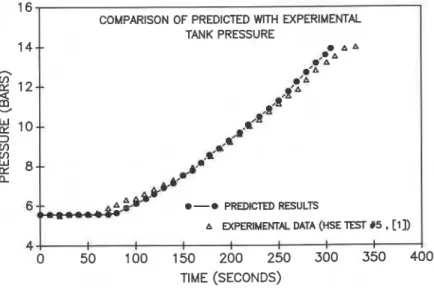
The tank pressure predicted by the model was compared with the pressure recorded during the experiment, (Figure I), and they are in excellent agreement. The numerical model
16
COMPARISON OF PREDICTED WITH EXPERIMENTAL
1
I
TANK PRESSURE320
COMPARISON OF PREDICTED WITH EXPERIMENTALLIQUID TEMPERATURE NEAR INTERFACE
I
#
A A 0-
0 PREDICTED RESULTSA MPERIMEMAL DATA (HSE Tm lr5,
TlME (SECONDS)
COMPARISON OF PREDICTED WITH EXPERIMENTAL LIQUID TEMPERATURE NEAR TANK BOllOM
300
--
00 '0' O A A A.295-
,O ,o' A ,o '0 A290
--
A O'gA A A A , '2'.285
--
oP
A sP
o '280
i A EXPERIMENTAL DATA (HSE TEST $5, [ln
0-
0 PREDICTED RESULTS275
I0
50
100
150
200
250
300
350
TlME (SECONDS)
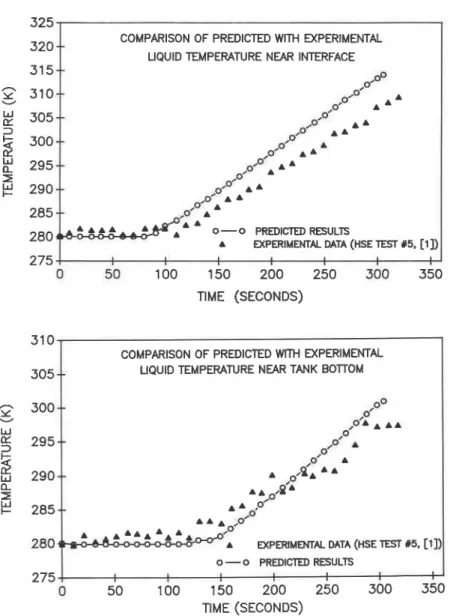
Fig. 2. Comparison of experimental tank temperature with predicted solution; (a) top of liquid, (b) bottom of tank.
predicts that the pressure relief valvc opens in 305 seconds. During the test, the valve opened at 312 seconds.
The predicted liquid temper;~ture is also in good agreement with the experimental data, especially during the initial 180 seconds of the test, (Figure 2). Figure 2a compares the temperature at the top of the liquid and Figure 2b at the bottom. Towards the end of the simulation, the model seems to overpredict the liquid temperature at the top of the liquid region.
The predicted temperatures of the vapour and vapour wetted wall were also found to be higher than the experimental ones. The main reason for this may be due to the fact that during the experimental test, the vapour-wetted wall was not engulfed con~pletely by the flames due to wind effects. Hence, the temperature of this segment remained low due to radiation heat transfer to the ambient air. Another factor influencing the vapour and liquid temperature variations between the experimental and predicted data is the quantity of impurities in the experimental fluid, which is not accounted for in the numerical model.
Effect of tank diameter on tan-
Simulations have been performed using the numerical model in order to study the effect of the tank size on the tank response when subjected to fire engulfment. For all simulations, the filling level is 80% and the rnaxinlum fire temperature 1100 K, which is reached within the first 10 seconds of the simulation. The tank diameter varies in a typical range of values from 0.6 m to 2.6 m.
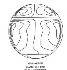
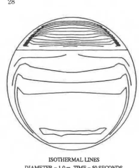
Since the flow field in the tank, for all simulations, follows a similar pattern, results are presented only for the 1.0 m tank. Figure 3, which depicts the flow streamlines in the tank at 50 and 100 seconds, indicates that two counter rotating eddies occur in the liquid region. The warmer liquid adjacent to the talk wall creates a boundary layer flow moving upward towards the interface and occupies the upper liquid region forcing the colder fluid to move downward and diffuse into the bulk liquid. Two recirculating eddies are also generated in the vapour space. This fluid motion causes some mixing to occur, however, as shown in Figure 4, which depicts the isothermal lines in the tank, the fluid is thermally stratified. The temperature difference
S'IREAMLINES DIAMETER = 1 .O m TIME = 50 SECONDS xRlwamw DIAMBTW = 1.0 m T M E = 100 SECONDS
ISOTHERMAL LINES
DIAMETER = 1.0 m. TIME = 50 SECONDS
LIQUID TEMP. [K]: MAX. 289.92. MIN. 280.0
VAPOUR TEMP. [KI: MAX. 379.52. MIN. 312.22
I S O n m w A L LINBS
DIAMmER = 1.0 m. TIMB = 100 SECONDS UQUID TEMP. [K]: MAX. 299.41. MN. 281.08
VAPOUR TEMP. [K]: M e 49223. MN. 41 8.44.
Fig. 4. Isothermal lines for the 1.0 m diameter tank at 50 and 100 seconds.
between isotherms in the liquid region is 1.0 K, while in the vapour space the difference is 10 K. The fluid temperature is uniform in the horizontal direction and decreases from top to bottom with the coldest region found just above the tank bottom. The liquid is warmer near the bottom of the tank due to direct heat input from below.
330
LIQUID TEMPERATURE PROFILES ALONG VERTICAL 325 DIAMETER AT TIME OF VALVE OPENING
Y
3
31 0A
'
5
7
>AA-'A
0-eDIA. o-oDIA. = = 0.6 1.0 rn rn u - A-ADIA. = 1.7 rn A-ADIA. = 2.0rn
285--
0-• DIA. = 2.6 rn 280--
H : DISTANCE FROM TANK BOllOM 275 0.0 0.1 0.2 0.3 0.4 0.5 0.6 0.7 0.8 0.9 1.0 H/
DIAMETERFig. 5. Temperature profiles in the liquid region along the vertical diameter for the tank sizes
The temperature profiles along the verlical diameter in the liquid region, at the time of valve opening, are illustrated in Figure 5 for all cases simulated. As shown the temperature gradient in the vertical direction, which indicates the strength of the stratification, decreases as the tank size increases. This decrease can be attributed to a better mixing of the liquid when the tank diameter increases.
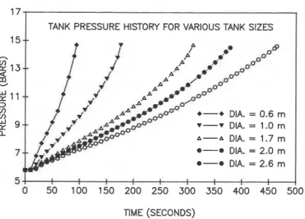
The tank pressure history for the tank sizes considered is shown in Figure 6. The pressure in the smaller tank rises rapidly and the valve opens in 95 seconds. As the tank diameter increases the rate of pressure rise decreases causing an increase in the time to valve opening. The valve opens at 180, 310, 378, and 464 seconds for the 1.0, 1.7, 2.0, and 2.6 m tanks
respectively.
1
TANK PRESSURE HISTORY FOR VARIOUS TANK SIZES1
*-• DIA. =
0.6
m r-r DIA. =1.0
m A-A DIA. = 1.7 m *-a DIA. =2.0
m @-a DIA. =2.6
m 54
II
0
50 100 150 200 250 300 350 400 450 500
TIME (SECONDS)Fig. 6. Tank pressure history for the cases simulated.
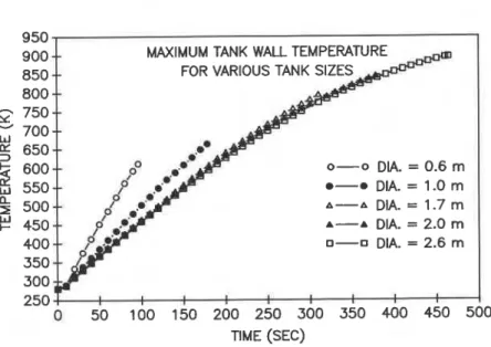
Another important parameter, which affects the response of the tank to heating conditions, is the tank wall temperature. As the wall temperature increases, the strength of the wall
decreases. This might lead to tank eruption and explosion due to the rising tank pressure. Figure 7, which shows the ninximum wall ceniperature for the cases simulated, indicates that the rate of telilperature rise decreases with an increase in the tank diameter. The difference in this rate,
L however, is negligible for the 1.7,2.0 and 2.6 m tanks. At the tinie of valve opening, the
maxiinum ta~rk wall temperature is greatest for the 2.6 ni tank and decreases as the tank size decreases; a result expected due the increase in ~hl: time required for the valve to open.
---
MAXIMUM TANK WALL TEM FOR VARIOUS 800 0-0 DIA. = 0.6
m
0-0 DIA. = 1 . 0 m A-A DIA. = 1.7 m A-A DIA. = 2.0 m 0-0 DIA. = 2.6 m TIME (SEC)Fig. 7. Maximum tank wall temperature for the cases simulated. CONCLUDING REMARKS
A numerical model has been developed to study the response of LPG tanks to fire conditions. The model has been used to simulate an experinlental test in order to compare the predictions with the test data. The comparisons indicated that despite the difficulties in accurately modelling the engulfing fm, the model can accurately predict the time to valve opening. The model, however, overpredicts the vapour and liquid temperatures, which may be a result of variations in the fire exposure during the test due to wind effects.
The model has been used to investigate the effect of the tank diameter on the tank response and on the thermal stratificatio~~ in the liquid region. The predicted results lead to the following conclusions:
(i) the time to first valve opening increases as the tank diameter increases; (ii) thermal stratification in the liquid region decreases as the tank size increases; (iii) the maximum tank wall temperature at the time of valve opening increases as the
diameter increases.
The cases simulated are for a symmetric fue heat flux and the results presented cannot be assunled to represent scenarios where the fire heat flux is not symmetric. Heat input
unsynlrnetries will cause completcly different free convective flows in the liquid region and hence a different temperature disuibution, wluch will affect the pressure rise. These conditions are now being investigated and the results will be presented in future publications.
ACKNOWLEDGEMENTS
This work was supported by the Transportation Development Center, Transport Canada, the Natural Sciences and Engineering Research Council, and the Society of International Gas Tanker and Terminal Operators Ltd..
REFERENCES
Moodie, K., Cowley, R.B., Denny, R.B., Small, L.M. and Williams, I., Fire Engulfment Tests on a 5 Tonne Tank, J. I-Iazardous Materials 20, (1988) 55-71. Birk, A.M., Modelling the Response of Tankers Exposed to External Fire Impingement,
J. Hazardous Materials, 20, (1988) 197-225.
Sousa, A.C.M., Wentzell, P.R. and Venart, J.E.S., Modelling of LPG Tanks Exposed to Fire, Heat and ~ e c h n o l o i ~ , 314, (1985) 1-23.
-
Hunt. D.L.M. and Ramskill. P.K.. A Descri~tion of ENGULF- a Com~uter Code to ~ o d e l the Thern~al ~ e s ~ o n i e of a ' ~ a n k ~ n & l f e d in Fire, UKAEA, ~ e i o r t No. SRD R 354, 1987.
Beynon,
G.V.,
Cowley, L.T., Small,L.M.
and Willinnis, I., Fire Engulfment ofLPG
Tanks: FIEATUP. a predictive model, J. Hazardous Materials 20, (1988) 227-238. Aydemir, N.U., Magapu, V.K.. Sousa. A.C.M. and Venan, J.E.S., Thermal Response Analysis of LPG Tanks Exposed to Fire, J. Hazardous Materids 20, (1988) 239-262.
Birk, A.M. and Oosthuizen, P.H., Model for (lie Prediction of Radiant Heat Transfer to a Horizontal Cylinder Engulfed in Flames, ASME R7-WADIT-52, 1982.
Kreith, F., and Aohn. M.S.,Princinles of Heat Transfer. 4th Edition, Hamer and Row publisher;, New ~ o r k , (I 986). a
Blinov. V.I. and Khudiakov. G.N.. (Reviewed bv Hottel. H.C.). Certain Laws ~ o v e m i n g Diffusive ~ u r n i n g of ~ & i d s , Fire ~ e i e a r c h , Abstracts and Review (1959) 1- 41.
Siege], P. and I<owel, J.R., Thermal Radiation Heat Transfer, 2nd Edition, Hemisphere Publication Corporation, Washington, D.C., 1981.
Maliska, C.P. and Raithby, G.C., A Method for Computing Three Dimensional Flows Using Non-Orthogonal Boundary Fitted Coordinates, Int. J. Numerical Methods in Fluids 4, (1984) 519-537.
Thompson, C.P., WIlkes, hT.S. and Jones, I.P., Numerical Studies on Buoyancy-Driven Turbulent Flow in a Rectang~~lar Cavity, Int. J. Numerical Methods in Engineering 24, 89-99, 1987.
Van Doormaal, J.P., and Raithby,G.D., Enhancements of the SIMPLE Method for Predicting Irlcompressible Fluid Flows, Num. Heat. Transfer, 7, 147-163, (1984). Hadjisophocleous, G.V., Numerical Modelling of LPG Horizontal Cylindrical Tanks Subjected to Heating Environments, Ph.D. Thesis, University of New Brunswick, (1989).
Anderson, C., Townsend, W., Zook, J. and Cuwgill, G., The Effects of a Fire Environment on a Rail Tank-car Filled with LPG, US Army Ballistic Res. Labs., Aberdeen Proving Ground, MD. PB241, Sept. 1974 (FRA-OR 8CD 75-31).
Appleyard, R.D., Testing and Evaluation of the Explosafe System as a Method of Controlling the Boiling Liquid Expanding Vapour Explosion, Technical Report # TP2740 (1980) prepared by Vulcan Industrial Packaging (Ex plosafe Division) for TDC, Transport Canada.