HAL Id: tel-02550427
https://hal.archives-ouvertes.fr/tel-02550427
Submitted on 22 Apr 2020HAL is a multi-disciplinary open access L’archive ouverte pluridisciplinaire HAL, est
Yohan Barbarin
To cite this version:
Yohan Barbarin. 1.55 µm integrated modelocked semiconductor lasers. Optics / Pho-tonic. Department of Electrical Engineering TU Eindhoven; ISBN: 9789038620138 -https://doi.org/10.6100/IR624757, 2007. English. �tel-02550427�
cked Semiconductor Lasers
Yoha
1.55 µm Integrated Modelocked
Semiconductor Lasers
Uitnodiging
Voor het bijwonen van de
openbare verdediging
van mijn proefscrift
1.55 µm Integrated
Modelocked
Semiconductor
Lasers
Maandag 2 April 2007
16.00 uur in het
Auditorium
(collegezaal 4) van de
Technische Universiteit
Eindhoven.
Aansluitend is er een
receptie in café
De Zwarte Doos
Yohan Barbarin
[email protected]1.55 µm Integrated Modelocked
Semiconductor Lasers
PROEFSCHRIFT
ter verkrijging van de graad van doctor aan de
Technische Universiteit Eindhoven, op gezag van de
Rector Magnificus, prof.dr.ir. C.J. van Duijn, voor een
commissie aangewezen door het College voor
Promoties in het openbaar te verdedigen
op maandag 2 april 2007 om 16.00 uur
door
Yohan Barbarin
prof.dr.ir. M.K. Smit en
prof.dr. D. Lenstra Copromotor: dr. E.A.J.M. Bente
This research was supported by the Towards Freeband Communication Impulse program of the Dutch Ministry of Economic Affairs (STW), the NRC Photonics program and the COST 288 frame work.
Copyright © 2007 Yohan Barbarin Printed in The Netherlands.
Cover from a painting of Mlle Pauline Calmette
CIP-DATA LIBRARY TECHNISCHE UNIVERSITEIT EINDHOVEN Barbarin, Yohan
1.55 µm integrated modelocked semiconductor lasers / by Yohan Barbarin. – Eindhoven : Technische Universiteit Eindhoven, 2007.
Proefschrift. – ISBN 978-90-386-2013-8 NUR 959
Contents
Contents... 4
Chapter 1 Introduction ... 9
1.1 Introduction... 9
1.2 Passive modelocking mechanism ... 10
1.3 Overview of the thesis ... 14
1.4 List of references... 17
Chapter 2 Modelocked laser theory and simulations... 21
2.1 Overview of modelocked laser theory... 21
2.2 Modeling of integrated semiconductor lasers... 23
2.2.1 Description of the model ... 23
2.2.2 Bandwidth limitation using a digital Bessel filter... 28
2.2.3 Implementation of the model in a program... 29
2.3 Simulation of symmetric and asymmetric 20 GHz RMLL... 31
2.3.1 Introduction... 31
2.3.2 Simulation of a symmetric RMLL... 31
2.3.3 Simulation of an asymmetric RMLL ... 39
2.3.4 Conclusion ... 46
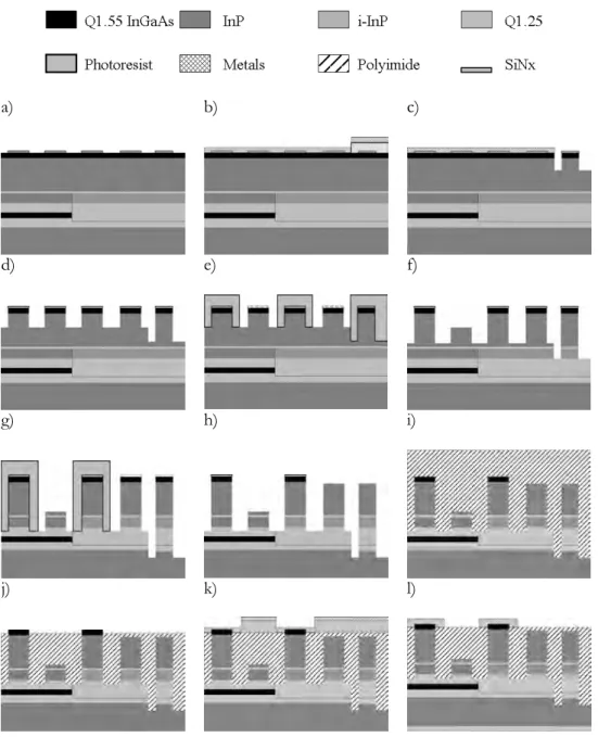
3.2.2 Complete chip processing... 55
3.3 Measurement of Active-Passive butt-joint loss and reflections ... 61
3.3.1 Introduction... 61
3.3.2 Butt-joint loss of COBRA passive-passive wafer... 61
3.3.3 Butt-joint reflection measurement method ... 62
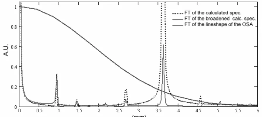
3.3.4 Modeling of the sub-threshold spectrum ... 64
3.3.5 Butt-joint reflectivity in ECLs on a JDSU active-passive wafer ... 67
3.3.6 Discussion of the method... 69
3.3.7 Minimization of butt-joint reflectivity in ECLs on a COBRA active-passive wafer... 69
3.3.8 Conclusion ... 72
3.4 Gain measurements of bulk SOA ... 73
3.4.1 Introduction... 73
3.4.2 Gain measurement method ... 74
3.4.3 Gain curve measurements... 75
3.4.4 Discussion of the method... 78
3.4.5 Differential gain measurement... 80
3.4.6 Conclusion ... 84
3.5 List of references... 85
Chapter 4 Application of deep-etched waveguides in AWGs and QD lasers.. 89
4.1 Introduction... 89
4.2 Compact AWG realized using a double-etch process. ... 91
4.2.1 Introduction... 91
4.2.2 Design of the AWG. ... 91
4.2.3 Measurements results of the compact AWG. ... 93
4.2.4 Effect of the reduction of the AAF ... 94
4.2.5 Conclusion ... 95
4.3 Deeply etched quantum dots lasers... 96
4.3.1 Introduction... 96
4.3.2 Fabrication of the quantum dots wafer ... 96
4.3.3 Fabry-Pérot laser results ... 98
4.3.4 Ring laser results... 99
4.3.5 Conclusion ... 102
4.4 List of references... 103
5.3 All active integrated Fabry-Pérot passively modelocked lasers... 111
5.3.1 Introduction... 111
5.3.2 20 GHz SCPM laser design and performance ... 111
5.3.3 40 GHz CPM laser design and performance... 114
5.4 All active 15 GHz integrated passively modelocked ring laser. ... 116
5.4.1 Introduction... 116
5.4.2 Design of the all active 15 GHz ring laser... 117
5.4.3 Modelocking region and RF spectra... 118
5.4.4 Output power of the RMLL... 120
5.4.5 Optical spectra of the RMLL ... 121
5.4.6 Autocorrelator results ... 123
5.4.7 Repetition rate... 124
5.4.8 Jitter measurements ... 125
5.4.9 Conclusion ... 127
5.5 Fabry-Pérot integrated extended cavity passively modelocked lasers .. 128
5.5.1 Introduction... 128
5.5.2 Design and fabrication of the EC-MLL... 128
5.5.3 18 GHz EC-MLL performance... 129
5.5.4 Conclusion ... 133
5.6 27 GHz integrated passively modelocked ring laser... 134
5.6.1 Introduction... 134
5.6.2 Modelocked laser device ... 134
5.6.3 Initial modelling of the modelocked ring laser ... 135
5.6.4 Experimental and simulation results... 135
5.7 List of references... 139
Chapter 6 Modelocked lasers for all optical clock recovery... 145
6.1 Introduction... 145
6.2 Optical clock recovery using a 20 GHz Fabry-Pérot modelocked laser 148 6.2.1 Introduction... 148
6.2.2 Experimental setup ... 148
6.2.3 20 Gb/s optical clock recovery ... 150
6.2.4 Timing jitter measurements of the 20 GHz recovered clock ... 151
6.2.5 Sampling oscilloscope traces of 20 GHz recovered clock... 153
6.3.2 Design of the RMLL... 158
6.3.3 Concept and design of a separate AOCR input ... 160
6.4 List of references... 163 List of acronyms ... 168 Summary ... 170 List of publications ... 172 Acknowledgements ... 176 Curriculum vitae ... 180
Chapter 1
Introduction
1.1
Introduction
A modelocked laser (MLL) is a much used laser source to obtain a periodic train of short light pulses. Different types of modelocked lasers with specific performance levels exist for various applications. Historically, passive modelocking was first observed in Nd doped glass lasers [1] that were passively Q-switched using saturable dye absorbers. Pulses down to approximately 1 ps were reported. Optically pumped organic dye lasers have a larger gain bandwidth which allows for pulses in the femtosecond range to be produced as well as wavelength tunability [2]. However, dye lasers have the disadvantage that they require expensive pump laser sources and the dye can degrade with time. Dye laser have been replaced over time by solid state lasers. Solid state lasers, based on ion-doped crystals, in particular Ti:Al2O3 [3] or glasses, are
at the present time mainly used when femtosecond pulses and/or very high pulse energies (up to Joules) are required. Ultra-wide spectra generated from such a laser provide directly a frequency comb [ 4 ], which is of high interest for frequency standards [5] and metrology applications. The repetition rate of many of the solid state lasers is typically limited to a couple of hundreds of MHz which is an issue for some applications. Diode pumped fiber lasers can be modelocked [6] to generate short pulses at telecom wavelengths. Multi-GHz repetition rates up to 40 GHz can be obtained with harmonic modelocking [7], however it requires an RF source for the modulation. The pulse durations achieved are limited down to 150 fs by the higher order nonlinearities in the doped fiber used. Semiconductor lasers can also be modelocked through different techniques. Semiconductor MLLs have the advantage that they can be directly electrically pumped, that they are very compact and can be cost effective when fabricated in high volumes. Picoseconds pulses with few tens of
lasers [8]. Very short pulses with high power can also be achieved in optically pumped Vertical External Cavity Surface-Emitting Lasers (VESCELs) [9].
Semiconductor MLL are of interest for a large number of applications which are not restricted to optical telecommunication. For instance, the fastest sampling oscilloscopes currently employ MLLs for optical sampling measurements [10] and in the near future expectations are high for the use of MLLs in high speed analogue to digital conversion [11]. In microelectronics systems, the integration density in circuits is continuously becoming higher and the copper links between the components and sections are becoming so thin that their resistance and associated power loss becomes a problem. The use of MLL pulse sources to interconnect CMOS devices and/or to distribute clock signals in high speed microprocessors [ 12 , 13 ] is investigated by microelectronics companies. A well known medical application of MLLs is the use of Ti-sapphire femtosecond modelocked lasers for surgery in for instance corneal refractive surgery [14]. New medical applications emerging are in optical coherence tomography and multiphoton imaging where semiconductor MLLs can be used in the telecom wavelength range and up to GHz level repetition rates [15,16]. Closer to optical telecommunication, in radio over fiber applications, optical transmitters can make use of MLLs [17].
The motivation for the development of the modelocked lasers in this thesis is their use as optical pulse sources in an All Optical Clock Recovery (AOCR) scheme [18] in Optical Time Division Multiplexing (OTDM) systems [19]. This work was part of the project “Key components for 160 to 640 Gb/s optical time domain multiplexing networking” from the Freeband Impulse program. The lasers presented in this thesis can also be used in some of the applications mentioned above. To introduce the reader to modelocked lasers of the type developed in this thesis, the mechanism of passive modelocking is presented in Section 1.2. This is followed by an overview of the contents of the thesis in Section 1.3.
1.2
Passive modelocking mechanism
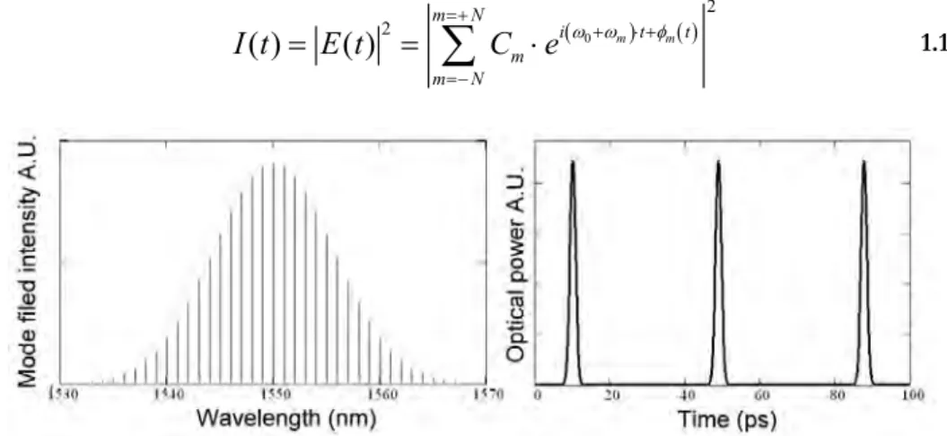
A modelocked laser, as the name suggests, is a laser with its longitudinal modes locked in phase. Assuming this and calculating the output power of such a laser by normalizing the electrical field (see Equation 1.1), the train of pulses of Figure 1.2.1 is obtained. In Equation 1.1, Cm are the intensities of the phase locked modes. The pulse width is inversely proportional to the optical bandwidth spectrum. The repetition rate depends on the spacing in frequency of the longitudinal modes of the laser cavity. Looking at the laser in a time-dependent view, in e.g. a Fabry-Perot (FP) cavity, there is a single pulse traveling up and down the cavity. The repetition rate of the output of the laser is the inverse of the roundtrip time of the pulse in the laser. The
roundtrip-( 0 ) ( ) 2 2 ( ) ( ) m m m N i t t m m N I t E t =+ C e ω ω+ ⋅ +φ =− = =
∑
⋅ 1.1Figure 1.2.1 Mode field intensity profile output power of a modelocked laser.
The modelocking mechanism can be achieved in different ways. The so-called active modelocking technique involves the modulation of the cavity losses at the free spectral range of the cavity or at a harmonic. This modulation is applied to a modulation device in the cavity using an RF source. All the longitudinal modes operating in the cavity are then modulated in intensity at the frequency of the mode-spacing and a constant phase relation will be established between them. In this way optical pulses are created. A passively modelocked laser has its longitudinal modes locked in phase without any RF source. The modes are locked in phase through an internal nonlinear process that couples the longitudinal modes. Shorter pulses can be achieved with passively modelocked lasers than with actively modelocked lasers. An efficient manner to passively modelock a laser is by introducing a Saturable Absorber (SA) in the cavity. In this thesis passive modelocking is studied using a saturable absorber that has a recovery time that is typically longer than the pulse duration achieved. This is called slow saturable absorber modelocking. This has been first discovered in dye lasers in 1966 [1] under Q-switching operation. The first passively modelocked dye laser in continuous operation was reported by French and Taylor in 1986 [20]. The theory of Haus for slow saturable absorber modelocking [21] explains the formation of short pulse as the result of an interaction between the gain saturation and the SA losses as experienced by a pulse traveling in the cavity. As a result of this interaction there is net gain in the cavity for the pulse for only a short period of time. This is illustrated in Figure 1.2.2. A positive net gain window is created when the saturation energy of the SA is several times lower than that of the amplifier and the relaxation time of the SA is faster than the gain recovery of the amplifier. In the semiconductor devices discussed in this thesis, a SA typically has a recovery time in
order of one ns. SAs with faster recovery do exist [22,23], however these cannot be used in planar monolithically integrated devices.
Figure 1.2.2 Gain and losses function of time in passively modelocked laser cavity using a slow saturable absorber.
When a pulse passes through a short SA or an amplifier, the shape of the pulse changes. The SA absorbs the leading edge of a pulse until it gets saturated, then the tail of the pulse is much less absorbed. This phenomenon shortens the pulse by making the leading edge steeper. The amplifier is also saturated during the amplification of a pulse. The leading edge is fully amplified but this is not the case for the tail of the pulse. This phenomenon shortens the pulse as well by reducing the tail end of the pulse. In fact, a wide pulse can then be completely reshaped and narrowed down after a number of roundtrips as shown by a simulation result presented in Figure 1.2.3. Here, a 15 ps wide pulse has been introduced in a MLL cavity and it has been shortened down to 1.8 ps. Also the maximum of the pulse has clearly moved roundtrip after roundtrip. This phenomenon, allows one to tune the repetition rate of a MLL through control of the pulse energy [24]. The optical bandwidth of the roundtrip gain and the nonlinear effects in a MLL limit the minimum pulse width that can be achieved in the laser.
Figure 1.2.3 Pulse reshaping and narrowing in a typical semiconductor modelocked laser cavity. A 15 ps pulse has been initially injected into the cavity.
A transform-limited pulse is a pulse which is as short as its spectral content allows. For instance, for a pulse with a hyperbolic secant square shape, the product of the Full Width at Half Maximum (FWHM) pulse times its optical bandwidth (∆f·∆t) is equal to 0.315 when the pulse is transform limited. When a transform-limited pulse propagates through a medium such as an optical fiber, amplifier or a SA, its time-bandwidth product increases due to dispersion and nonlinearities in the medium. The pulse, when it exits the medium, is not transform-limited anymore: the pulse is chirped (see Figure 1.2.4). The chirp of an optical pulse can be understood as the time dependence of its instantaneous frequency. For instance an up-chirp (down-chirp) means that the instantaneous frequency of the pulse raises (decreases) within the pulse duration. Vice versa, an unchirped pulse has a nearly constant instantaneous frequency. A linearly chirped pulse can be compressed to a transform limited shape by passing the pulse through appropriate dispersive elements of opposite sign [25].
1.3
Overview of the thesis
The objective of the presented work was to realize compact InP/InGaAsP modelocked lasers, operating in the 1.55 µm wavelength range, in the active-passive integration technology. These devices should be used as optical pulse sources in an AOCR application [18] in OTDM systems [19]. The active-passive integration technology allows for the fabrication and integration of different types of components and thus many different devices on a single chip. The two principal categories of components are those using passive waveguides and those using Semiconductor Optical Amplifiers (SOAs). The integration technique used is a so-called “butt-joint coupling” technique in which the index guiding structure for the passive and active components, is at the same height on the chip. The quality of the transition between the active and the passive waveguide structure, the butt-joint, is essential for modelocked lasers as will be explained in Chapter 5. In this project, the modelocking mechanism used is passive modelocking using a slow Saturable Absorber (SA). The SA is a short SOA section that is reversely biased. In this project, work was largely concentrated on ring laser type cavities. Indeed, much of the published research effort has been focused on monolithic modelocked lasers in Fabry-Pérot (FP) type configurations. A ring configuration has however significant advantages. Firstly, the repetition rate of the laser can be controlled accurately by photolithography as opposed to a device with cleaved facet mirrors. Secondly, a ring laser typically operates as a Colliding Pulse Modelocked (CPM) [26] laser where two counter-propagating pulses collide in the saturable absorber. This improves the modelocking performance, in particular the stability. Furthermore, when active-passive technology is used the laser can be directly integrated with other devices such as an all-optical switch or a pulse compressor [27]. The rise in speed of the optical telecommunication networks creates a drive to increase the repetition rate of modelocked lasers to values like 40 GHz or more. The repetition rate of a modelocked laser is inversely proportional to its cavity length, thus to its foot print. In the case of ring lasers, sharp bends in the waveguides are necessary which in turn required high index contrast waveguides. The active-passive technology presented in this thesis integrates high contrast passive waveguides and 40 GHz laser cavities can be realized.
From the first realization of integrated Ring Mode Locked Lasers (RMLLs) using active-passive integration and a demonstration of a device at 27 GHz [28][Section 5.6], many issues came up. First, the understanding of the modelocking mechanism and other dynamics using a bulk In/InGaAsP material needed to be better understood. To address this issue, a simulation tool of RMLL was developed. It is a bi-directional time domain model which is presented in Chapter 2. Simulation results showed that symmetrical cavities show a much wider operating range for stable modelocking. The transitions from a modelocked state of the laser to another
Another important issue which came out from the first RMLL realization was the necessity to reduce all the reflections inside the modelocked laser cavity and in particular the reflections of the butt-joint at the active-passive interfaces. Special efforts have thus been made to characterize the optical losses and reflections at the butt-joint [30] and to minimize them. The fabrication technology of the active-passive wafer that has been developed during this project in the COBRA institute is presented in Chapter 3. The active-passive butt-joint reflection has been reduced to a sufficiently low value of less than -50 dB [31]. A reflectivity of -50 dB is a minimum value required for good laser operation [32].
As mentioned previously, the aim of the project was to realize RMLLs with a 40 GHz repetition rate or higher. To validate techniques required to achieve high repetition rate RMLL designs, the realization of more compact devices through the use of deep etching has been investigated in Chapter 4. Results are presented on, at that time, the world’s most compact AWG using a double-etch technique [33], and the world’s first InAs/InP quantum dot (QD) lasers employing narrow deeply etched ridge active waveguides in the 1.55 µm wavelength region [34]. The performance of the QD lasers appears not to be affected by sidewall recombination effects. Shallowly and deeply etched FP lasers show the same performance. Results obtained from a compact QD ring laser with a free spectral range close to 40 GHz are presented. Before realizing a final RMLL design on an active-passive wafer, a series of all-active devices has been designed, fabricated and characterized. The same layerstack with a bulk gain layer was used as in the active parts of the active-passive material. These all-active chips provided material for the gain measurements presented in Chapter 3 and allowed to look further into short pulse laser characterization techniques and to test designs for reducing reflections from other intra-cavity components. The results of the all-active MLLs are presented in Chapter 5. Firstly, 20 GHz and 40 GHz linear all active Fabry-Pérot MLL (FPMLL) lasers have been successfully fabricated. Modelocking has been achieved with these lasers in the CPM and Self Colliding Pulse Modelocked (SCPM) configurations. Pulse lengths down to 1.6 ps (at 20 GHz) have been observed. A 40 GHz repetition rate was demonstrated in a CPM laser with a Saturable Absorber (SA) positioned in the center of the FP cavity [8]. All-active 15 GHz RMLLs have also been successfully fabricated. These lasers show a relatively good timing stability due to the ring configuration. Measured output pulses are highly chirped and an FWHM bandwidth of up to 4.5 nm was obtained. These results have been published in [35]. Such lasers with high bandwidth pulses and compatible with active-passive integration are of great interest for Optical Code Division Multiple Access (O-CDMA) applications, where information is coded in the spectrum [36]. Finally, first results from MLLs realized on an active-passive wafer are presented in Section 5.5. Passive modelocking has been demonstrated in these integrated Extended Cavity FPMLLs with minimized intra-cavity reflections. Pulses of 2.1 ps duration and with a small pedestal have been observed. The pulses are close to transform-limited.
The use of a MLL for the AOCR application and a special RMLL design for AOCR are presented in Chapter 6. To begin with, initial test experiments for AOCR and clock frequency division using a 20 GHz Fabry-Pérot MLL are presented. Many characteristics of the AOCR could be quantified. Then, the design of a 40 GHz MLL laser in a ring configuration for an active-passive wafer is presented. The design utilizes all the minimizations of small intra-cavity reflections. Finally, for AOCR application a novel way to couple the optical input signal into the MLL via a separate waveguide has been designed for the 40 GHz RMLL. The timing jitter of the clock recovered from this laser is expected to be sufficiently low to comply with the telecom requirements at 40 GHz [19]. This expectation is based on the accumulated results presented in this thesis and as summarized in the last chapter.
The material contained in the following papers and conference proceedings has been used in the different chapters of this thesis:
Chapter 3:
• Applied Optics, Vol. 45, Issue 35, pp. 9007-9012, (2006) • IEEE PTL, Vol. 17, Issue 11, pp. 2265-2267, (2005)
• IEEE LEOS Benelux 2005 Mons, Belgium, pp. 249-252 (2005) Chapter 4:
• IEEE PTL Vol. 16, issue 11, pp. 2478-2480, (2004) • IEEE PTL Vol. 18, issue 24, pp. 2644-2646, (2006) Chapter 5:
• IEEE PTL, Vol.17, Issue 11, pp. 2277-2279. (2005) • ECOC’05, Glasgow, Scotland, Vol. 3, pp. 673-674, (2005). • Optics Express, Vol. 14, Issue 21, pp. 9716-9727, (2006)
1.4
List of references
1 A.J.D. Maria, D.A. Stretser, H. Heynau, “ Self mode-locking of lasers with saturable absorbers” Applied Physics Letters, Vol. 8, Issue 7, pp. 174-176, (1966)
2 R.L. Fork, B.I. Greene and C.V. Shank “Generation of optical pulses shorter than 0.1 psec by colliding pulse mode locking” Applied Physics Letters, Vol. 38, Issue 9, pp. 671-672, (1981)
3 P.F. Moulton, "Spectroscopic and laser characteristics of Ti:Al2O3," Journal Optical Society of America B, Vol. 3, Issue 1, pp. 125-133, (1986)
4 L. Matos, D. Kleppner, O. Kuzucu, T. R. Schibli, J. Kim, E. P. Ippen, and F. X. Kaertner, "Direct frequency comb generation from an octave-spanning, prismless Ti:sapphire laser," Optics Letters, Vol. 29, Issue 14, pp. 1683-1685, (2004)
5 R. Holzwarth,; M. Zimmermann, T. Udem, T.W. Hansch, “Optical clockworks and the measurement of laser frequencies with a mode-locked frequency comb” IEEE Journal of Quantum Electronics, Vol.37, Issue 12, pp.1493-1501, (2001)
6 I.N. Duling III, "All-fiber ring soliton laser mode locked with a nonlinear mirror," Optics Letters, Vol. 16, Issue 8, pp. 539-541,(1991)
7 B. Bakhshi, P.A. Andrekson, “40 GHz actively modelocked polarisation maintaining erbium fibre ring laser” Electronics Letters , Vol. 36, Issue 5, pp.411-413, (2000) 8 Y. Barbarin, E.A.J.M. Bente, M.J.R. Heck, Y.S. Oei, R. Nötzel and M.K. Smit
“Passively Modelocked 20 and 40GHz Bulk InGaAsP Lasers” in Proceeding ECOC’05, Glasgow, Scotland, (2005).
9 U. Keller and A. C. Tropper, “Passively modelocked surface-emitting semiconductor lasers” Physics Reports, Vol. 429, Issue 2, pp. 67-120, (2006)
10 M. Shirane, Y. Hashimoto, H. Yamada and H. Yokoyama, “A Compact Optical Sampling Measurement system Using Mode-Locked Laser-Diode Modules” IEEE Photonic Technology Letters, Vol. 12, Issue 11,pp. 1537-1539, (2000)
11 Y. Han, B. Jalali, “Photonic time-stretched analog-to-digital converter: fundamental concepts and practical considerations” Journal of Lightwave Technology, Vol. 21, Issue 12, pp. 3085-3103. (2003)
12 G.A. Keeler, B.F. Nelson, D. Agarval, C. Debaes, N.C. Helman, A. Bhatnagar, D.A.B. Miller, “The benefits of ultrashort optical pulses in optically interconnected systems”, IEEE Journal of Selected Topics in Quantum Electronics, Vol. 9, Issue 2, pp. 477-485. (2003).
13 Kobrinsky, M.; Block, B.; Zheng, J-F.; Barnett, B; Mohammed, E.; Reshotko, M.; Robertson, F.; List, S.; Young, I.; Cadien, K. "On-Chip Optical Interconnects." Intel Technology Journal, Vol. 8, Issue 2, ISSN 1535-864X (May 2004).
14 T. Juhasz, F.H. Loesel, R.M. Kurtz, C. Horvath, J.F. Bille, G. Mourou, “Corneal refractive surgery with femtosecond lasers” IEEE Journal of Selected Topics in Quantum Electronics, Vol. 5, Issue 4, pp. 902-910, (1999)
15 J. Bewersdorf, S.W. Hell, “Picosecond Pulsed Two-Photon Imaging With Repetition Rates of 200 and 400 MHz”, Journal of microscopy, Vol. 191, Issue 1, pp. 28-38, (1998) 16 W. Drexler “Ultrahigh-resolution optical coherence tomography” Journal of
Biomedical Optics, Vol. 9, Issue 1, pp. 47-74 (2004)
17 A.J.C Vieira, P.R. Herczfeld, A. Rosen, M. Ermold, E.E. Funk, W.D. Jemison, K.I Williams, “A mode-locked microchip laser optical transmitter for fiber radio” IEEE transactions on Microwave Theory and Techniques, Vol. 49, Issue 10-2, pp. 1882-1887, (2001)
18 S. Arahira, Y. Ogawa, “Retiming and reshaping function of all-optical clock extraction at 160 Gb/s in monolithic mode-locked laser diode” IEEE Journal of Quantum Electronics, Vol. 41, Issue 7, pp. 937- 944, (2005)
19 E. J. M. Verdurmen, “Optical Time domain add-drop multiplexing employing fiber nonlinearities” PhD Thesis, Eindhoven University of technology, ISBN-13: 978-90-386-1923-1, (2006)
20 P.M.W. French, J.R. Taylor “Passive Mode Locking of an Energy Transfer Continuous-Wave Dye Laser” IEEE Journal of Quantum Electronics, Vol. 22, Issue 8, pp. 1162-1164, (1986)
21 H.A. Haus, “Theory of mode locking with a slow saturable absorber,” IEEE Journal of Quantum Electronics, Vol. 11, Issue 9, pp. 736-746, (1975)
22 H.A. Haus “Theory of mode locking with a fast saturable absorber”, Journal of Applied Physics, Vol. 46, Issue 7, pp. 3049-3058, (1975)
23 U. Keller, K.J. Weingarten, F.X. Kärtner, D. Kopf, B. Braun, I.D. Jung, R. Fluck, C. Hönninger, N. Matuschek and J. Aus der Au “Semiconductor Saturable Absorber Mirrors (SESAM’s) for Femtosecond to Nanosecond Pulse Generation in Solid-State Lasers” IEEE Journal Of Selected Topics In Quantum Electronics, Vol. 2, Issue 3, pp. 435-453, (1996)
24 S. Arahira, Y. Ogawa, “Repetition-frequency tuning of monolithic passively mode-locked semiconductor lasers with integrated extended cavities” IEEE Journal of Quantum Electronics, Vol. 33, Issue 2, pp. 255-257, (1997)
25 H.G. Winful, “Pulse compression in optical fiber filters”, Applied Physics Letters, Vol. 46, Issue 6, pp. 527-529 (1985)
26 S Bischoff, J Mørk, T Franck, S D Brorson, M Hofmann, K Fröjdh, L Prip and M P Sørensen “Monolithic colliding pulse mode-locked semiconductor lasers” Quantum
Including Integrated Passive Pulse Shaping Components” IEEE Journal of Selected Topics in Quantum Electronics, Vol. 12, Issue 2, pp 265-276, (2006)
28 Y. Barbarin, E.A.J.M Bente, M.J.R. Heck, J.H. den Besten, G. Guidi, Y.S. Oei, J.J.M. Binsma, M.K. Smit, ” Realization and Modeling of a 27-GHz Integrated Passively Mode-Locked Ring Laser”, IEEE Photonic Technology Letters, Vol. 17, Issue 11, pp. 2277-2279, (2005)
29 Y. Barbarin, E.A.J.M Bente, L. Mussard, G. Servanton, Y.S. Oei, R. Nötzel and M.K. Smit “Gain Measurements of Fabry-Pérot InP/InGaAsP Lasers using an Ultra High Resolution Spectrometer” Applied Optics, Vol. 45, Issue 35, pp. 9007-9012 (2006) 30 Y. Barbarin, E.A.J.M. Bente, C. Marquet, E.J.S Leclère, J.J.M. Binsma and M.K. Smit.
"Measurement of Reflectivity of Butt-Joint Active-Passive Interfaces in Integrated Extended Cavity Lasers" IEEE Photonics Technology Letters, Vol. 17, Issue 11, pp. 2265-2267, (2005)
31 Y. Barbarin, E.A.J.M Bente, T. de Vries, J.H. den Besten, P.J. van Veldhoven, M.J.H. Sander-Jochem, E.J. Smalbrugge, F.W.M.v. Otten, E.J. Geluk, M.J.R. Heck, X.J.M. Leijtens, J.G.M. van der Tol, F. Karouta, Y.S. Oei, R. Nötzel and M.K. Smit “Butt-Joint Interfaces in InP/InGaAsP waveguides with Very Low Reflectivity and Low Loss” IEEE LEOS Benelux 2005 Mons, Belgium
32 R.W. Tkach and A.R. Chraplyvy, "Regimes of feedback effects in 1.5 um distributed feedback lasers", Journal of Lightwave Technology, Vol 4, pp. 1655-1661, (1986) 33 Y. Barbarin, X.J.M. Leijtens, E.A.J.M. Bente, C.M. Louzao, J. Kooiman, M.K. Smit.
“Extremely small AWG demultiplexer fabricated on InP by using a double-etch process” IEEE Photonics Technology Letters, Vol. 16, Issue 11, pp. 2478-2480, (2004) 34 Y. Barbarin, S. Anantathanasarn, E.A.J.M. Bente, Y.S. Oei, M.K. Smit and R. Nötzel
"1.55 µm Range InAs/InP Quantum Dot Fabry-Pérot and Ring Lasers using Narrow Deeply Etched Ridge Waveguides" IEEE Photonics Technology Letters, Vol. 18, Issue 24, pp. 2644-2646, (2006)
35 Y. Barbarin, E.A.J.M Bente, M.J.R. Heck, Y.S. Oei, R. Nötzel and M.K. Smit "Characterization of a 15 GHz Integrated Bulk InGaAsP Passively Modelocked Ring Laser at 1.53µm" Optics Express, Vol. 14, Issue 21, pp. 9716-9727, (2006)
36 C. Ji, R. G. Broeke, Y. Du, Jing Cao, N. Chubun, P. Bjeletich, F. Olsson, S. Lourdudoss, R. Welty, C. Reinhardt, P. L. Stephan, and S. J. B. Yoo “Monolithically integrated InP-based photonic chip development for O-CDMA systems” IEEE Journal of Selected Topics in Quantum Electronics, Vol. 11, Issue 1, pp. 66-77 (2005).
Chapter 2
Modelocked laser theory
and simulations
2.1
Overview of modelocked laser theory
In this thesis 1.55 µm semiconductor modelocked lasers are investigated and developed. This requires the development of a simulation tool of such lasers in order to get to a comprehensive understanding of the mechanism of passive modelocking and to be able to design devices. The model that has been developed and which is presented in this chapter is a bi-directional time domain model for Ring ModeLocked Lasers (RMLLs). The modelocking mechanism studied and used in this thesis is a passive modelocking using a slow Saturable Absorber (SA). The SA is a short Semiconductor Optical Amplifier (SOA) section that is reversely biased. The model developed here is applied to the bulk 1.55 µm InGaAsP active medium, which is used in the active-passive integration scheme presented in Section 3.2 and in [1]. The model may also be used, with the appropriate parameters, with quantum well gain media. The passive components are passive waveguides and passive couplers and the active components are SOAs which are either: an amplifier, a SA, or an isolation section between amplifier and SA.
The first reported work on the modeling of modelocking using a slow SA is from Haus [2] in the middle of the seventies of the previous century. Then the research in this field had continued with the development of semiconductor modelocked lasers in the nineties. As identified and discussed by Avrutin et al. [3] in 2000, there are two main types of time-domain modelocking theories. There are the lumped-element models [4], [5] and the fully distributed time-domain models [6]. Another approach that is well developed is a traveling wave model [7,8,9]. Recently Heck et al. [ 10 ] presented a model with a lumped-element approach where the propagation of the pulse through the SOA and the SA were calculated using a distributed time-domain model. The SOA rate equations used in his model are based
linear effects are included in the model presented in this chapter. The model developed here is fully in the time domain except for the bandwidth limitation in the laser. It is bi-directional to describe realistic laser systems which usually operate with pulses traveling in both directions. For the description of the SOA, the model of Tang and Shore has been extended with bidirectional fields, separate radiative and non-radiative carrier recombination processes [12] and a logarithm gain-carrier relation. This gain relation has been validated for the bulk material used in the RMLL described in [13] and Section 3.4. The effect of the limited optical bandwidth of the SOA is not included in the rate equations of the SOA, but in a separate element in the model. This element is a bi-directional digital low-pass filter which stabilizes the system by limiting the bandwidth each roundtrip, in accordance with the spectral gain profile of the amplifier.
In the following section, the model for RMLL is described in details. Finally in Section 2.3, the model is used for the simulation of symmetric and asymmetric 20 GHz modelocked ring lasers. Taking into account the results of the simulations and the experimental results from different modelocked lasers that are presented in Chapter 5, a new RMLL design has been produced. This new design is presented in Chapter 6.
2.2
Modeling of integrated semiconductor lasers
2.2.1 Description of the modelIn this section a bi-directional time domain model of a modelocked ring laser is presented that is based on a set of rate equations for a SOA. This system of differential equations relates the density of photons and charge carriers in the device to the injection current. Five different components are used in the extended cavity RMLL: passive waveguides, amplifiers, absorbers, isolation sections and a coupler. In this model, the ring laser is divided into segments that we assume equal in optical length (Figure 2.2.2). There are five types of segment required for the different components. Uniform photon and carrier densities (for active components) are assumed in the segments. The time for the light to travel through one segment is 25 fs which is the discretization time (Tseg). Each 25 fs the evolution of the photon densities (Clock Wise and Counter Clock Wise) and carrier densities is calculated for all segments. Then the photon densities are transferred to the neighboring segments and the carrier density values are kept in the same active segments for the next step.
The SOA rate equations of the model presented here include nonlinear effects in the same formalism as Tang and Shore in [11]. The nonlinear effects are Carrier Heating (CH), two photons absorption (TPA) and Ultrafast Nonlinear Refraction (UNR). The rate equations have been extended to take into account bidirectional fields (CW and CCW). Also, the model presented here makes the distinction between radiative and non-radiative carrier recombination processes [12]. Finally, in the rate equations of the SOA a logarithmic gain model is used that has been validated experimentally in [13] and the Section 3.4 of this thesis. The gain-carrier relation used is given in Equation 2.1, where aN is the linear gain coefficient, N0 the material transparency carrier density and N the carrier density. The relation is illustrated in Figure 2.2.1. The average carrier density in the amplifier inside the laser above threshold is around two times N0. A linear gain-carrier relation is commonly used in lasers since the typically the variation in carrier density in the amplifier in time is over a limited range. However it can be seen that the slope of the curve becomes smaller at higher values of N and that the linear gain coefficient would need to be corrected [4]. Using the logarithmic relation, no correction is needed. Furthermore, this relation is more flexible for the simulation of various type of RMLL with different amplifier length and thus different averaged carrier densities.
0 0 ln m N g aN N N = ⋅ ⋅ 2.1
Figure 2.2.1 Plot of the logarithmic gain carrier density relation. The averaged carrier densities in the amplifier and the SA in a modelocked ring laser are indicated.
Each SOA segment is described by the following rate equations:
( ) ( ) 2 0 1 1 2 0 2 2 1 1 3 1 1 1 2 1 4 2 1 2 ln 1 S S S S N C C S S N S S C S Loss S Loss N S C N t C S S ⋅ − ⋅ + ∂ = ⋅ − ⋅ − ⋅ − ⋅ ⋅ + ⋅ ∂ + ⋅ + 2.2 ( ) ( ) 2 0 1 1 2 0 2 2 2 2 3 2 1 2 2 2 4 2 1 2 ln 1 S S S S N C C S S N S S C S Loss S Loss N S C N t C S S ⋅ − ⋅ + ∂ = ⋅ − ⋅ − ⋅ − ⋅ ⋅ + ⋅ ∂ + ⋅ + 2.3 ( ) ( () ) ( ) 2 0 1 1 2 2 0 2 3 1 2 3 1 2 2 1 2 ln 1 N N N N C C S S N N S S C S S A N B N C N Wp t C S S ⋅ − ⋅ + ∂ = − + ⋅ + ⋅ + − ⋅ − ⋅ − ⋅ + ∂ + ⋅ + 2.4 ( ) ( ) ( ) ( ) 2 0 1 2 1 1 2 0 1 3 4 1 2 2 1 2 0 ln ln 1 N C S S C S S N N C C S S z C S S N ϕ ϕ ϕ ϕ ϕ ⋅ ⋅ + + ⋅ + ∂ = − ⋅ − ⋅ + ∂ + ⋅ + 2.5 ( ) ( ) ( ) ( ) 2 0 1 2 1 1 2 0 2 3 4 1 2 2 1 2 0 ln ln 1 N C S S C S S N N C C S S z C S S N ϕ ϕ ϕ ϕ ϕ ⋅ ⋅ + + ⋅ + ∂ = − ⋅ − ⋅ + ∂ + ⋅ + 2.6
Here S1 and S2 are the Clock Wise and Counter Clock Wise photon densities,
φ1 and φ 2 are the CW and CCW phases. In the two photon density equations for CW (2.2) and CCW propagation (2.3): CS0 is the linear gain contribution; CS1 is the nonlinear gain compression factor due to two-photon absorption; C2 is the nonlinear
CN3 and C2 are the same contributions as CS0, CS1, C2 and CN3; A is the inverse of the carrier lifetime; B is the bimolecular recombination rate; C is the Auger recombination coefficient and Wp is the pump rate. In the two phase equations: Cφ0, Cφ1, Cφ3 and C2 are the same contributions as Cs0, Cs1, C2 and Cs3, Cφ4 is the ultrafast nonlinear refraction coefficient. In detail: 0 0 0 0 0 1 0 2 2 2 2 3 2 2 3 2 2 2 1 2 2 1 2 3 1 2 2 1 1 2 1 C 2 S N S N S C aN Vg N C aN Vg N C T aN Vg Surf N Surf Surf C Vg Vg C T Vg Surf C Vg C ϕ ϕ α ε ω ε ω ε ω α ε ω ε ω = ⋅Γ ⋅ ⋅ = ⋅ ⋅ = ⋅ ⋅ ⋅ ⋅ ⋅ ⋅ ⋅ ⋅ = ⋅ ⋅ ⋅ ⋅ = ⋅ ⋅ ⋅ ⋅ = ⋅ ⋅ ⋅ ⋅ ⋅ Γ Γ = ⋅ ⋅ ⋅ ⋅ Γ = = = = = ( ) 2 2 2 3 2 2 3 2 3 0 1 2 4 ' 4 2 2 1 2 N
scat clad seg freecar seg seg seg S
Vg C Vg C N aN Vg N
Loss Loss L Loss L
Loss Loss T T C B C n Vg c ϕ ϕ β ω β ω α β ω ω Γ = Γ ⋅ ⋅ ⋅ ⋅ = ⋅ ⋅ ⋅ ⋅ = ⋅ ⋅ ⋅Γ ⋅ ⋅ Γ + ⋅ ⋅ = = ⋅Γ ⋅ = Γ ⋅ ⋅ ⋅ ⋅ ⋅ = = =
Where Γ the linear confinement factor, Vg the group velocity, ε2 the nonlinear gain compression factor to TPA, ω the pulsation, ε1 the nonlinear gain compression factor, Surf the surface of the active region, Γ2 the confinement factor for TPA, Γ2’
the confinement factor for UNR, c the speed of light, Tseg the time segment, Lseg the physical length of one segment, β the spontaneous emission coupling factor, αN the carrier density linewidth enhancement factor and αT is the temperature linewidth enhancement factor. β2 is the coefficient for two-photon absorption and n2 is the nonlinear gain refractive index. All the parameters used are listed in Table 2.2.1.
The Saturable Absorber (SA) is a short SOA that is reversely biased [15]. It is described with the same rate equations as the amplifier without carrier injection. In the SA in an operating MLL the carrier density varies in time between low background values and the transparency carrier density value. In Figure 2.2.1, it can be seen that within this range, the slope of the gain-carrier relation curve varies by a significant amount. The logarithmic gain-carrier relation has its limit when the carrier density in the SA is very low. The absorption then becomes unrealistically high. This is prevented by introducing a minimum carrier density background value in the SA. It has been reported that the carrier lifetime of a saturable absorber depends of the reverse bias voltage applied [16], but such a relation has not been implemented in the model. The carrier lifetime is the only parameter that is tuned. The model presented here is bidirectional, thus two pulses can meet in the SA. For a very short SA (less than a few wavelengths), coherent effects need to be taken into account. However for
Table 2.2.1: Parameters used in the model
Symbol Description value
aN Linear gain coefficient 4.05·10-20 m²
N0 Transparency carrier density 0.4·1024 m-3
Γ Linear confinement factor 0.259
Γ2 Confinement factor for TPA 0.5
Γ2’ Confinement factor for UNR 0.4
Vg Group velocity 80·106 m/s
ε1 Nonlinear gain compression factor 0.2 W-1
ε2 Nonlinear gain compression factor to TPA 200 W-2m-1
ω Pulsation / wavelength 1.55 µm
Surf Surface of the active region 0.12 x 2.0 µm²
n2 Nonlinear gain refractive index -3.5·10-16m²/W
Tseg Time segment 25 fs
β Spontaneous emission coupling factor 10-5
β2 Coefficient for TPA 37cm/GW
A One over the carrier life time 1.67·10-9 s-1
B Bimolecular recombination rate 2.602·10-16 m3s-1
C Auger recombination coefficient 5.269·10-41 m6s-1
αT Temperature linewidth enhancement factor 2.0 αN Carrier density linewidth enhancement factor 4.0
Loss1 Scattering loss and free carrier loss in the cladding 2000 m-1
Loss2 Free carrier absorption within the active layer 5.0·10-22 m²
non-the SOA listed above. The limitation of non-the optical bandwidth is done separately at each roundtrip using a bi-directional digital low-pass filter [19]. Section 2.2.2 describes in details the digital filter used.
In this thesis, a RMLL cavity where the two counter propagating pulses experience the same optical path, but in opposite direction, is called a symmetric cavity. If not, the cavity is asymmetric. Besides, a modelocked laser which has two counter propagating pulses meeting in a SA, is in a Colliding Pulse Modelocked (CPM) [20] configuration. This is automatically the case for a RMLL (in case there are no provisions to make it unidirectional). Shorter pulses are generally obtained with such a configuration [20]. Figure 2.2.2 presents a diagram of a possible RMLL symmetric configuration. At the top of the figure, a coupler element couples the light in and out of the ring. This is done coherently for both directions in the model. At the bottom of the figure, in the middle of an amplifier is a SA isolated by two isolation sections. The white segments are passive waveguides. The bandwidth limitation obtained by filtering is done for each direction just before the light is coupled out of the ring. The model presented here has been developed for RMLL cavities, but it can be easily modified to a Fabry-Pérot cavity with two end-mirrors. The implementation of the model in program is briefly presented in 2.2.3.
Figure 2.2.2 Diagram of the symmetric ring modelocked laser segmented for the simulation. The connections between the coupler, the ring and the Bessel filters are
2.2.2 Bandwidth limitation using a digital Bessel filter
In order to keep the model fully in the time domain, a digital filter has been introduced to simulate the bandwidth of the SOA. A low-pass digital Bessel filter [19] has been chosen for this. Its parameters have been set so that the transmission curve is close to the measured gain curve (Section 3.4) as can be seen from Figure 2.2.3.a). Important is also that such a digital Bessel filter has a very low distortion of the phase. The filter is a digital difference equation (Equation 2.7). The difference equation computes the output electrical field strength and phase at the time n, based on present and past input electrical field and past output electrical field.
[ ]
[
]
[
]
0 1 order order k l k l y n b x n k a y n k = = =∑
⋅ − +∑
− ⋅ − 2.7In Equation 2.7, x[n] is the present input signal (complex field amplitude),
x[n - k] is the array with the past input signal, y[n - k] is the array with the past output
signal (complex field amplitude), a is a vector of filter feedback coefficients, and b is a vector of filter feedforward coefficients. These coefficients determine the properties of the filter. One possible signal flow graph for the filter is given in Figure 2.2.3.b). The storage of past samples is represented by boxes labeled "z-1". This diagram is used because it can be directly converted to the frequency domain by replacing all time-domain signals by their respective transforms [21]. The idea contained within the Z-transform was previously known as the "generating function method".
a) b)
Figure 2.2.3 a) The transfer function of the digital filter used, plotted with the
measured bulk SOA gain as a function of the normalized frequency (Ω = ω·Tseg / 2π ).
measured to be 21.6 THz (0.086 in a normalized frequency) [13]. The order of the filter that is required has been tested. The 14th order turned out to be sufficiently
robust for our application. In the calculations the a and b coefficients need to be used with an accuracy that is two orders of magnitude greater than the order of the filter. This type of digital filter conserves the causality of the signal but it has a delay. The delay is one over the normalized frequency cut, which in our case corresponds to approximately 22 segments of 25 fs. This delay can be compensated in the passive region of the ring where only the passive losses are playing a role. The use of a digital filter is much simple than using a Fourier Transform (FT), spectral filtering and back FT as in [10].
2.2.3 Implementation of the model in a program
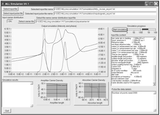
The model has been implemented in a C program using LabWindows® CVI. A
screenshot of the interface created is given in Figure 2.2.4. The program requires at least two input files. The first one contains all the parameters listed in Table 2.2.1, with in addition the parameters defining the design of the RMLL and the coefficients of the digital Bessel filter. The second input file contains tables with CW and CCW input light intensities and phases for a time series. A third input file can be used containing the initial carrier densities of the active elements.
As mentioned above, every 25 fs the photon densities (CW and CCW) and carrier densities are calculated for all segments. Then the photon densities are transferred to the next segments and the carrier density values are saved in active segments for the next step. The integration of the rate equation is done using the Runge-Kutta method with a fixed step size [ 22 ]. At each roundtrip, the output intensities and phases are plotted on the interface and saved at the end of a text file. The carrier densities of the amplifier, isolation sections and SA are saved for each roundtrip in a different file and plotted on the interface in two graphs. The simulation of a 20GHz RMLL with 1000 active elements and for a 1000 roundtrips takes ~50 minutes using a laptop under Windows XP with a 1.6 GHz Intel Pentium M 730 processor.
2.3
Simulation of symmetric and asymmetric 20 GHz
RMLL
2.3.1 Introduction
The model previously introduced has been used to study a symmetric and an asymmetric 20 GHz RMLL design. The results are presented in the two following sections. The RMLLs can be realized with the COBRA technology [23]. The choice of the design parameters studied has been guided by the results obtained experimentally from an 18 GHz integrated extended cavity Fabry-Pérot MLL (EC-FPMLL) presented in Section 5.5. Indeed the dimensions of the RMLL amplifier and SA studied are similar to the experimental design of the EC-FPMLL. Simulation results show that a symmetrical cavity is better for stable modelocking. Transitions from the modelocked state of the laser to other operating regimes can be explained by the model. The simulation results of the asymmetric RMLL show that a modelocking regime is more difficult to achieve. The competition between the CW and the CCW modes in the asymmetric case makes the laser more unstable in most situations. However, it can clearly be seen that depending on the amount of absorption in the SA in the cavity, the laser can operate with two counter-propagating pulses with significantly different peak intensities.
2.3.2 Simulation of a symmetric RMLL
The design of a 20 GHz symmetric RMLL is plotted in Figure 2.3.2. The cavity is segmented for the simulation in different sections as shown previously in Figure 2.3.1. The total length of the ring laser is 4 mm (2000 segments). The two amplifiers are 472 µm long (236 segments). The choice of the length of the SA is based on the length of the SAs in successfully modelocked FPMLL devices presented in Section 5.5: absorber lengths of 10 and 12.5 µm. In a ring cavity, there are two counter-propagating pulses which meet in the SA. It can be seen as two FPMLL lasers joined at the SAs; the resulting SA is then two times as long. For the simulation, the SA was set at 22 µm long (11 segments). It is isolated from the amplifiers by two 16 µm long (8 segments) isolation sections. The light is coupled in and out from the ring with a coupler with 50% out-coupling ratio.
Figure 2.3.2 Design of a symmetric 20 GHz modelocked ring laser on an active-passive wafer. The active region is 1000 µm long and centered is a 22 µm long SA. The isolation sections are 16 µm long.
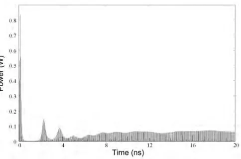
The model includes spontaneous emission, which allows simulating the self-starting of the laser. As an example, a simulated output power during start-up of the laser is plotted in Figure 2.3.3 (without light injected) for settings that lead to a stable modelocked state. Below 0.3 ns, the amplifiers amplify the small amount of spontaneous emission and the carrier concentration increase to large values. Three aspects can be identified in the start-up of the modelocked laser. The laser starts with relaxation oscillation behavior which ends after five or so oscillations. The second aspect is that the modelocking action of the absorber can be seen right from the start and after only 2 to 3 ns the laser produces pulses and only a small amount of CW background light. Then the pulse length decreases further in time as shown in Figure 2.3.3 (right axis). After that the third aspect can be seen. The short pulse length makes that the self-phase modulation becomes important. The short pulse may break-up a couple of times before its phase profile becomes stable. The laser then settles to a stable modelocked state.
Figure 2.3.3 Simulated output power and calculated pulse width of the laser as a
function of time. The laser is self-starting. I = 65 mA τSA = 11 ps.
Simulations of the symmetric RMLL have been performed for different amplifier current and SA carrier lifetime values to establish the stability region for modelocking. To save computer time, two 2 ps pulses with a null phase have been injected into the cavity to start the simulation. The laser threshold is 57.5 mA. The different regimes of the laser are plotted in Figure 2.3.4. The laser is properly modelocked for amplifier current values between 62 mA and 75 mA and SA carrier lifetime values between 9 and 15 ps. The results obtained for parameters in the modelocked regime on the boundary of the stability region are stable over 5 ns. At high current injection (> 75 mA) and for any SA carrier lifetime, the laser is in a Q-switching regime. For short SA carrier lifetime (<7 ps) and a current in the amplifier which is not too high, the laser produces short pulses, modulated in intensity. This regime is a two-dimensional quasi-periodic dynamic (taurus) [ 24]. There are two regions where the laser is unstable. In the first region instable around 65 mA amplifier current and 15 ps SA carrier lifetime, a second pulse in the roundtrip time attempts to be present. In the second region unstable around 72.5 mA amplifier current and 9 ps SA carrier lifetime, the laser switches irregularly between a self-pulsating regime to more stable state. Each regime is studied in more detail in the following paragraphs.
Figure 2.3.4 Different regimes of the symmetric 20GHz RMLL function of amplifier current and SA carrier lifetime. The pulse width is mentioned in picoseconds if the laser is modelocked.
In the stable modelocking region, as can be seen in Figure 2.3.4, the pulse width increases with the current, except next to the unstable region. At lower current, the pulse is less intense; it saturates less the SA which vice-versa narrows down the pulse more efficiently. In the same way the pulse width decreases with the carrier lifetime of the SA, except close to the unstable regimes. The most stable modelocked regime (over 20 ns simulated) has been found for 65 mA amplifier current and 11 ps SA carrier lifetime. The simulated output power as a function of time is plotted in Figure 2.3.5. The measured pulse width is constant after 8 ns and the amplitude modulation is small (<10%). The pulse obtained is plotted in Figure 2.3.6 with the corresponding calculated optical spectrum. The pulse is 0.95 ps wide with a 70 mW peak power and it is slightly down-chirped (65 GHz). Unidirectional simulations of Heck et al. predicted up-chirped pulses with higher chirp values. The change of sign is attributed to the CPM configuration. Using a Fourier Transform (FT), the optical spectrum has been calculated with 100 pulses. The calculated spectrum is 2.6 nm at FWHM; the pulse is almost transform-limited. The chirp of the pulses stays limited due to the integrated extended cavity.
Figure 2.3.5 Simulated output power of the 20 GHz symmetric RMLL function of time. Two low power 2 ps pulses with a phase null were injected in both direction of the
cavity to speed up the start of the laser. I = 65 mA τSA = 11 ps.
Figure 2.3.6 Simulated output pulse shape and chirp with the corresponding calculated optical spectrum. Width = 0.95 ps , Peak power = 70 mW ; Chirp = 65 GHz (~linear);
Bandwidth = 2.6 nm; for I = 65mA & τSA = 11ps.
The two dimensional quasi-periodic regime at a short SA recovery time (<7 ps) is illustrated by the simulated output power of the laser in Figure 2.3.7. This regime is stable after 5 ns. The peak intensities of the pulses vary from 120 mW to 60 mW every 1.3 ns (770 MHz). In the same way, the pulse width varies from 0.75 ps to 1.05 ps.
absorption is higher. The amplitude modulation can be reduced by increasing the gain in the cavity. Indeed, simulations with a higher injection current in the amplifier show that the modulation decreases and pulses narrow down. But, if the current is increased further, pulses start to break-up. No proper modelocking without amplitude modulation has been simulated for this design at such a short SA recovery time.
Figure 2.3.7 Simulated output power of the 20 GHz symmetric RMLL as a function of time with a relatively short SA lifetime. Two low power 2 ps pulses with a phase null were injected in both direction of the cavity to speed up the start of the laser.
I = 62.5mA, τSA = 5ps.
a) b)
Figure 2.3.8 Simulated output pulses for the two extreme cases, I = 62.5mA τSA = 5ps:
a) Peak power = 122mW, width = 0.75 ps, down chirp = 30GHz (nonlinear) b) Peak power = 58 mW, width = 1.05 ps, down chirp = 50GHz (~linear)
Figure 2.3.9 Simulated pulse width function of time for I = 62.5mA τSA = 5ps.
Longer timescale Q-switching like variations in output power are observed in combination with short pulse output with repetitive pulse break-up. These phenomena that occur in the modelocked laser at high injection current (over 76 mA in this design) can be understood by analyzing the simulated time series in detail. The short pulses tend to become more intense and more narrow. This makes that the short pulses start to break up. In some cases there is a continuous cycle of the short pulse breaking up, then a new similar short pulse emerges which in turn breaks up again, and this continues. An example of such behavior is shown in Figure 2.3.10 over a 10 ns span. The pattern repeats itself every 2.55 ns (450 MHz). The envelope of the time series is not a single frequency oscillation [24], thus this regime is a quasi periodic dynamic state with high dimension (> 3). The evolution of the pulse break up and subsequent emerging of another pulse from the tail of the initial pulse during the 2.55 ns period is shown in Figure 2.3.11. After 35 roundtrips there are two pulses that follow each other. The new pulse takes over from the initial one at a different relative position in the cavity and the phenomenon repeats itself.
Figure 2.3.10 Simulated output power of the 20 GHz symmetric RMLL as a function of time at higher current values. Two low power 2ps pulses with a phase null were injected in both direction of the cavity to speed up the start of the laser. I = 80mA τSA = 7ps.
Figure 2.3.11 Pulse break-up evolution. The pulse shape in shown for a series of
roundtrips. I = 80mA τSA = 7ps.
Figure 2.3.12). For the same carrier lifetime, at around 62 mA in the amplifier, the gain is not sufficient to supply a second pulse, thus it is stable. At 65 mA there is sufficient gain to have a small second pulse in the tail of the first pulse which makes the laser unstable. Above 70 mA, the two counter propagating pulses in the cavity are more intense and deplete the gain in the amplifier more deeply. Therefore no other pulses can build up.
Figure 2.3.12 Simulated output power of the 20 GHz symmetric RMLL in dB scale as
function of time for one selected roundtrip, τSA = 15ps. Depicted are the results for 3
different amplifier currents.
2.3.3 Simulation of an asymmetric RMLL
The next laser design studied, is asymmetric for the two counter-propagating pulses, is plotted in Figure 2.3.13. When two counter-propagating pulses are in the cavity, they meet in the SA and in the passive waveguide at the right-hand side of the coupler. The CCW pulse enters the SOA which has just been depleted by the CW pulse. Such a design is intended to investigate the possibility of having an integrated RMLL operating in a unidirectional regime since there is a roundtrip gain difference expected for the pulses in the two directions. It is of interest to achieve unidirectional operation without the use of an optical isolator which is not available for integration at the moment. The SA is positioned at the side of the amplifier. A 16 µm long (8 segments) section isolates the SA from the amplifier. The length of the SA is the same as the symmetric device studied in Section 2.3.2: 22 µm (11 segments).The simulation results show that depending on the driving conditions of the RMLL, the laser can have two counter-propagating pulses with different intensities or operates in
Figure 2.3.13 Design of an asymmetric 20 GHz modelocked ring laser on an active-passive wafer. The active region is 1000 µm long, at the side is a 22 µm long SA. The single isolation section is 16 µm long.
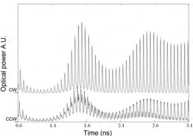
As mentioned in Section 2.3.2, it is possible to simulate the self-starting of the laser. The result of the two simulated output powers of the laser as a function of time is plotted in Figure 2.3.14. Here the time axis has been shifted for one of the output signals such that when two pulses in the two plotted output channels coincide, the two pulses traveling inside the laser cavity overlap in the SA. In this example, the RMLL supports two counter-propagating pulses in the cavity. The long time scale modulation of the CW and CCW output powers is similar to the one in the symmetric case that has been presented in Figure 2.3.3. However in the asymmetric case the building up of the pulses is different. First, it can be seen that the CW output power is more powerful than the CCW one. Then, the CW pulse builds-up in the same way as the pulses in the symmetric design, but not the CCW pulse. The initial “coarse” CCW pulse is not synchronized in the SA with the CW pulse. As the CW pulse is more powerful, it suppresses the CCW pulse, but a second CCW pulse builds-up that overlaps with the CW pulse in the SA. At the end, the laser has two counter-propagating pulses with different intensities.
Figure 2.3.14 Simulated output power (CW and CCW) of the laser as a function of time. The time reference is the SA. In the CCW direction a pulse builds-up that is
synchronized to the CW pulse, both pulses meet in the SA. (I = 65 mA τSA = 11 ps)
Simulations of the asymmetric RMLL have been performed for different amplifier current values and SA carrier lifetimes. As with the calculations on the symmetric design, in order to save computer time, two 2 ps pulses with a null phase have been injected into the cavity to start the laser. Pulses have the same intensity and are synchronized to meet in the SA. For this design, the lasing threshold is 55 mA. The first general observation is that, this configuration is much less stable than the symmetric design. The instability originates directly from the competition between the CW and the CCW modes. It is suspected that there is also a numerical stability issue in the model for calculations over periode longer than 5 ns. Part of the instability observed in the laser simulation can be attributed to the numerical discretization of the signals which is turns out to be more critical with different counter-propagating pulses. In particular the saturable absorber might require more than the 11 segments currently used. Amplifier current and SA carrier lifetime settings that gave rise to states which showed stable behavior over 5 ns have been analyzed further. These operating points are presented in Figure 2.3.15. For operating points where two counter-propagating pulses are supported, the ratio in peak power and the pulse widths for the two directions are indicated.
Different modes of operation can clearly be seen. Like the symmetric device simulated in Section 2.3.2, the pulse widths of the counter-propagating pulses increase with the current in the amplifier and decrease with τSA. The chirp of the pulses stays
dynamics of high dimension), just as the symmetric device. For a relatively short SA carrier lifetime (< 9 ps) and a current in the amplifier which is not too high (<65 mA), the laser produces short pulses modulated in intensity. The modulation depth of the envelope is indicated as a percentage in Figure 2.3.15. This modulation increases at higher amplifier current and at lower SA carrier lifetime.
Figure 2.3.15 Different regimes of the asymmetric 20 GHz RMLL as function of amplifier current and SA carrier lifetime. If the laser is modelocked the ratio between the CW and CCW pulses is mentioned with the pulses width.
The most stable states are indicated as the light grey areas in Figure 2.3.15. From the location of these areas the conclusion can be drawn that the SA carrier lifetime (τSA) is the most important parameter to control the asymmetry between the
CW and CCW output pulses.
At low τSA (<9 ps) the laser operates in a near-unidirectional regime as shown in
Figure 2.3.16. The resulting pulses are plotted in Figure 2.3.17 for I = 60 mA τSA = 8
ps. The CW pulse has a peak power of 95 mW and a width of 0.95 ps. The down chirp is 60 GHz, but with a plateau near the maximum intensity. The CCW pulse has
wider than the CCW one. The CW pulse has a peak power of 120 mW and a width of 1.45 ps when the CW pulse has a peak power of 45 mW and a width of 0.95 ps.
For τSA > 13 ps the two counter-propagating pulses can have almost the same
peak power but the CCW pulse width is slightly narrower. The energy balance between the CW and the CCW regimes is not really constant. A modulation with a period larger than 4 ns is commonly observed from the simulation.
Figure 2.3.16 Simulated output power of the asymmetric 20 GHz RMLL as a function
of time. After 8 ns, the laser is quasi unidirectional (CW). I = 60 mA τSA = 8 ps.
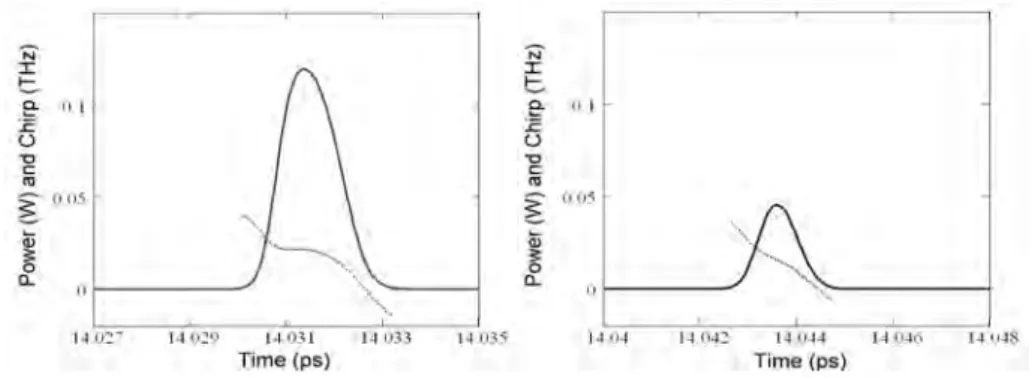
Figure 2.3.17 Simulated CW and CCW output pulses of the asymmetric 20 GHz RMLL
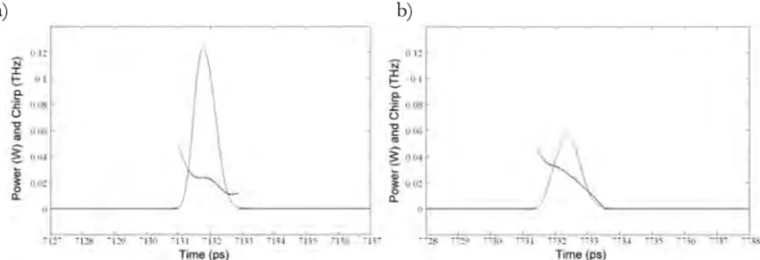
when the laser is quasi unidirectional. I = 60 mA τSA = 8 ps.
CW: Peak power = 95mW, width = 0.95 ps, down chirp = 60GHz (nonlinear) CCW: Peak power = 6 mW, width = 0.75 ps, down chirp = 30GHz ( nearly linear)
Figure 2.3.18 Simulated CW and CCW output pulses of the asymmetric 20 GHz RMLL
I = 67.5 mA τSA = 11 ps.
CW: Peak power = 120mW, width = 1.45 ps, down chirp = 50GHz (nonlinear) CCW: Peak power = 45 mW, width = 0.95 ps, down chirp = 50GHz (nearly linear)
A regime which was not perfectly stable in the symmetric regime is however more stable in the asymmetric case. The region is indicated in dark grey areas in Figure 2.3.15, it is for τSA = 5 ps and 65 mA < I < 70 mA. At the same settings, the
symmetric laser produces pulses heavily modulated in intensity. The asymmetric simulations show pulses of different intensities and pulses width with a modulation in peak power <15%. The CW and CCW time series over 14 ns are shown in Figure 2.3.19. The CW and CCW pulses are plotted in Figure 2.3.20. The CW pulse has a peak power of 115 mW and a width of 1.35 ps and the CW pulse has a peak power of 65 mW and a width of 0.8 ps.
Figure 2.3.19 Simulated output power of the asymmetric 20 GHz RMLL as a function
Figure 2.3.20 Simulated CW and CCW output pulses of the asymmetric 20 GHz
RMLL when the laser support two pulses for I = 67.5 mA τSA = 5 ps.
CW: Peak power = 120mW, width = 1.35 ps, down chirp = 50GHz (nonlinear) CCW: Peak power = 45 mW, width = 0.8 ps, down chirp = 50GHz (nearly linear)
A second asymmetric design has been studied. It is plotted in Figure 2.3.21. Two active regions are used: a long one for the amplifier which is 1000 µm long (2000 segments) and a short one for the SA 26 µm (13 segments). No isolation section is needed. This configuration is very similar to the previous one mentioned. Indeed, the counter-propagating pulses meet in the SA which is now “far” from the amplifier. Consequently the pulses then also meet at the right-hand side of the amplifier, just as in the design presented previously. The CCW has depleted the amplifier just before the CW pulse enters. Also here it was found that the SA carrier lifetime controls the asymmetry between the CW and CCW output pulses. The pulse widths (CW and CCW) increase with the current in the amplifier and decrease with τSA.
Figure 2.3.21 Design of a symmetric 20 GHz modelocked ring laser on an active passive wafer. The active region is 1000µm long the SA is 26 µm long.