HAL Id: ensl-00102139
https://hal-ens-lyon.archives-ouvertes.fr/ensl-00102139
Submitted on 29 Sep 2006
HAL is a multi-disciplinary open access
archive for the deposit and dissemination of
sci-entific research documents, whether they are
pub-lished or not. The documents may come from
teaching and research institutions in France or
abroad, or from public or private research centers.
L’archive ouverte pluridisciplinaire HAL, est
destinée au dépôt et à la diffusion de documents
scientifiques de niveau recherche, publiés ou non,
émanant des établissements d’enseignement et de
recherche français ou étrangers, des laboratoires
publics ou privés.
A novel internal waves generator
Louis Gostiaux, Henri Didelle, Stéphane Mercier, Thierry Dauxois
To cite this version:
Louis Gostiaux, Henri Didelle, Stéphane Mercier, Thierry Dauxois. A novel internal waves generator.
Experiments in Fluids, Springer Verlag (Germany), 2007, 42 (1), pp.123-130. �ensl-00102139�
ensl-00102139, version 1 - 29 Sep 2006
L. Gostiaux · H. Didelle · S. Mercier · T. Dauxois
A novel internal waves generator
Received: date / Accepted: date
Abstract We present a new kind of generator of inter-nal waves which has been designed for three purposes. First, the oscillating boundary conditions force the fluid particles to travel in the preferred direction of the wave ray, hence reducing the mixing due to forcing. Secondly, only one ray tube is produced so that all of the energy is in the beam of interest. Thirdly, temporal and spatial frequency studies emphasize the high quality for tempo-ral and spatial monochromaticity of the emitted beam. The greatest strength of this technique is therefore the ability to produce a large monochromatic and unidirec-tional beam.
Keywords Internal waves · Stratified fluids
1 Introduction
Stratified fluids are nowadays a field of paramount im-portance in fluid mechanics and are carefully studied the-oretically, experimentally and numerically by a large and always increasing scientific community. The underlying reason is, of course, the identification of many crucial phenomena appearing in the oceanic and atmospheric environments, where the stratification cannot be over-looked. The possibility to reproduce in a laboratory ex-periment conditions close to theoretical hypotheses is, of course, a very important way to validate theoreti-cal ideas developed in the last decades. Indeed, if one will always rely on in situ observations for the final de-cisive tests, new fundamental ideas are usually derived
L. Gostiaux, T. Dauxois
Laboratoire de Physique, UMR-CNRS 5672, ENS Lyon, 46 All´ee d’Italie, 69364 Lyon c´edex 07, France
Email: [email protected],[email protected] H. Didelle, S. Mercier
Laboratoire des ´Ecoulements G´eophysiques et Industriels (LEGI), UMR 5519 CNRS-UJF-INPG, 21 rue des Martyrs, 38000 Grenoble, France
within an oversimplified framework that cannot be re-produced in a real environment. Among many difficul-ties, let us mention just a few. The linear stratification hypothesis is almost always used in theoretical works despite the complicated oceanic or atmospheric strat-ification (Thorpe 2005). Internal waves are also often considered as monochromatic plane waves, while oceanic measurements usually report a beam-like structure, with a width smaller than a wavelength (Lam et al. 2004, Gerkema et al. 2004). The paradox of internal waves im-pinging onto topography (Dauxois and Young 1999) was solved for a linear oblique slope which can only be a poor description of a real seamount (Eriksen 1998). It is not satisfactory to test this last theoretical example by considering a beam impinging onto a curved topography in a fluid with a real and complicated stratification (ex-ponential, thermocline, mixed layer,...). Indeed, possible disagreements between theoretical and experimental re-sults might always be attributed to one of these three hypothesis which are not fulfilled in the experimental test. Controlled experiments in a simplified framework are therefore of paramount importance.
In a laboratory experiment, one can identify three main difficulties: the preparation of a stratified fluid with a controlled stratification, the generation and the visu-alizationof internal waves propagating within this fluid. The first difficulty was rapidly solved thanks to the well-known double bucket method and its improved versions (Oster 1965, Hill 2002, Benielli and Sommeria 1998). The visualization difficulty has been nicely solved in the last decade by two different techniques: the Schlieren method, on the one hand, later improved into the mod-ern quantitative synthetic Schlieren method (Dalziel et al 2000), gives time resolved density fields; on the other hand, the particle image velocimetry (PIV) technique provides time resolved velocity fields (Fincham and Del-erce 2000). However, the generation of monochromatic plane waves remains a crucial problem from the experi-mental point of view. We propose in this article a new ex-perimental set-up that is able to provide a single monochro-matic and unidirectional large beam.
2
The paper is organized as follows. In section 2, we briefly review existing generation methods, with a spe-cial emphasis on their limitations. In Sec. 3, we present the new internal waves generator. In the following sec-tion 4, we analyze the internal waves which are generated with a particular emphasis on its temporal, and spatial properties. Section 5 concludes the paper.
2 Review of existing generation methods
2.1 Important properties of internal gravity waves Internal waves in a continuously stratified fluid are shear waves that propagate with a phase velocity perpendic-ular to their group velocity. The density stratification allows the propagation of such waves by generating a restoring force. This latter is characterized by the Brunt-V¨ais¨al¨a frequency N , which corresponds to the vertical oscillation frequency of water masses in a local density gradient. It is defined as N2= −(g/ρ)(dρ/dz) where g is
the gravity, ρ the density and z the vertical coordinate. The frequency N will be kept constant in the remainder of the paper.
In such a stratified fluid, it is well-known that the dispersion relation for linear internal gravity waves is
ω = N sin θ, (1)
where ω is the temporal frequency and θ the angle of the wave vector with the vertical direction. This disper-sion relation emphasizes that for a fixed frequency, the direction in which the shear propagates is fixed and is denoted σ. This direction is also found to be orthogonal to the direction of propagation of the energy, denoted s. The study of internal waves generation must there-fore take into account these very unusual and restrictive geometrical conditions. Moreover, it is very important to notice that the spatial wavelength of the wave does not appear in the dispersion relation (1). There is no mech-anism of wavelength selection other than the physical boundary conditions imposed by the forcing technique. This last point will be of first importance in the follow-ing.
2.2 Oscillating bodies
The simplest experiments on internal waves emission use oscillating bodies as radiation sources and, more pre-cisely, in a two-dimensional set-up, a vertically oscil-lating cylinder (see the sketch in Fig. 1(a)). The first experiment was performed by G¨ortler (1943) in a two-dimensional setup. Nonetheless, as this experiment is of-ten forgotof-ten, one usually refers to the seminal exper-iment by Mowbray and Rarity (1967). This is nowa-days a simple laboratory set-up, often used in labora-tory tutorials at the undergraduate level. In the simpli-fied two-dimensional set-up, these generators emit four
beams of internal waves, making a constant angle with the horizontal. A typical resulting pattern is presented in Fig. 1(b). Recent three dimensional experiments with an oscillating sphere have reported striking double cones (Peacock and Weidman 2005).
a) b)
c) d)
e) f )
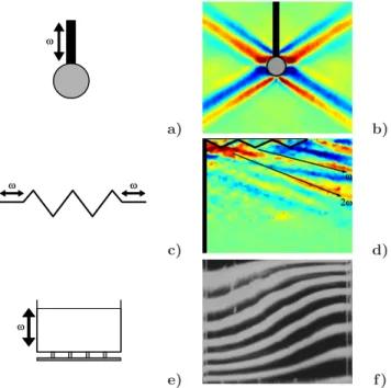
Fig. 1 (Color online) Principles and internal waves patterns for the three previous internal gravity wave generators. Panel (a) presents the sketch of a vertically oscillating cylinder. Panel (b) shows the resulting four rays as captured with a synthetic Schlieren technique. Panel (c) presents the paddle-like generator, while panel (d) shows a typical instantaneous PIV measurement. Note harmonic waves propagating in dif-ferent directions. Panel (e) presents the parametric excitation principle while panel (f) shows the resulting internal wave pattern (Benielli 1995).
As the wavelength does not enter the dispersion re-lation (1) of internal waves, it is absolutely non trivial, a priori, to predict the spatial structure of the beam. This question has been at the origin of several theoret-ical studies (Thomas and Stevenson 1972, Hurley 1997, Hurley and Keady 1997, Hurley and Hood 2001, Voisin 2003) which have proposed a nontrivial scaling of the beam spatial structure by the size of the object, the vis-cosity of the fluid and the emission frequency. In all cases, the beam envelope does not contain a full wavelength. Therefore, it is difficult to use these sources to study spatial properties of internal waves.
2.3 Paddle-like generators
It has also been proposed to generate directly a shear motion in the stratified fluid by using a multi-bladed folding paddle (McEwan 1973, Cacchione and Wunsch 1973, Teoh et al. 1997, Silva et al. 1997, Ivey et al. 2000,
Gostiaux et al. 2006) : see the sketch in Fig. 1(c). The flow generated by such a device corresponds to the su-perposition of two shear waves propagating in opposite directions along the zig-zag paddle, each one being inde-pendently solution of the internal waves’ equations. Such a set-up thus generates two beams propagating sym-metrically leftwards and rightwards (resp. upwards and downwards) when the paddle is set horizontally (resp. vertically) as in Teoh et al. (1997). Locating a vertical wall close to the paddle (see vertical black thick line in Fig. 1(d)) allows to avoid a second beam: moreover, be-cause of the reflection of the leftward beam on this wall, one may increase artificially the width of the rightward beam.
The energy transmission is proportional to the sine of the angle between the paddle and the along-direction of the beam. To gain in amplitude, one might therefore pro-pose to tilt the paddle orthogonally to the desired beam. One realizes immediately, however, that the generated shear is no more the superposition of two internal wave beams. Consequently it will excite strong nonlinearities. Intermediate position between the horizontal and this inclination can be proposed, this method, however, still generates higher harmonics. As shown in Fig. 1(d) (see Gostiaux et al. (2006) for additional details), the main part of the energy is transmitted to a beam of internal wave of frequency ω, while higher harmonics nω are also excited by the oscillating paddle. Their frequencies be-ing higher, their propagation angles are also larger (see Fig. 1(d)) and a screen can therefore be located appropri-ately to remove most harmonics (Gostiaux et al. 2006). Fortunately, in Ivey (2000), this effect was avoided since the excitation frequency ω was larger than half of the Brunt-V¨ais¨al¨a. In conclusion, as avoiding harmonics gen-eration is of primary importance for energy fluxes mea-surements and comparisons with theoretical predictions, especially for low frequency ratios ω/N , such a method is not ideal.
2.4 Tidal-like excitation
Finally, a third way of generating internal waves has been proposed and realized in a form of a global excitation of internal waves. A vertical periodic motion of the fluid container (see the sketch in Fig. 1(e)) acts as a pertur-bation of the gravity force on the whole fluid. Tidal-like excitations by barotropic forcing (Ivey 89, Gostiaux 2006) also excite globally the fluid. Resonant modes are selected and can be focused on internal waves attrac-tors. This excitation is highly dependent of the size and shape of the fluid domain, and relies on resonances of the enclosed geometry itself (Maas et al. 1997) as shown in Fig. 1(f).
The first very limitation is that oscillating vertically a large tank is, of course, very difficult and cannot be easily performed. In addition, the whole stratified fluid is thus
excited so that it is not possible to discern how internal waves, generated in one part of the tank, might encounter independently a topography, or another internal wave, in another part of the tank.
3 The new solution for internal waves generation
As briefly motivated in the previous section, a new prin-ciple for internal wave generation has to be proposed, if a monochromatic plane wave is necessary for laboratory experiments. The key idea is to create physical bound-ary conditions that effectively propagate within the fluid interior, instead of a stationary forcing.
3.1 Mechanism of the generator
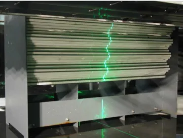
The generator consists of a pile of 24 expanded PVC sheets (2 × 36 × 150 cm) enclosed in a parallelepiped half-opened box and free to slip one over the other. The plates are weighted with thin lead sheets so that they are buoyantly neutral in water; it minimizes friction forces between plates. They are thus separated by 2.2 mm one from the other. Two rectangular holes in each plates al-low two identical camshafts (see Fig. 2(a)) to go through the pile, imposing the relative position of the plates. At rest, the plates are sinusoidally shifted, due to the he-licoidal repartition of the cams (see Fig. 2(b)). The ro-tation of the camshafts applies a periodic motion to the plates which propagates upward (resp. downward) for a clockwise (resp. anti-clockwise) rotation. The eccentric-ity of the camshafts defines the amplitude of oscillation of the plates, namely 6 cm peak to peak. A perspective view of the generator can be seen in Fig. 3.
To optimize the emission process, the generator is slightly tilted in direction of the emitted beam, i.e. the di-rection of shear propagation. In the following, we gener-ate a downward propagating beam (defined by the direc-tion of the group velocity) corresponding to an upward propagating shear (direction of the phase velocity). As anticipated, the device can easily generate upward prop-agating beams by inverting the sign of rotation of both camshaft.
3.2 Flow visualization
We performed experiments in the 13 meters diameter cir-cular tank of the Coriolis Plateform in Grenoble, filled with 90 cm of linearly stratified fluid at 3% correspond-ing to a Brunt-V¨ais¨al¨a period of TBV = 11.7 ± 0.2 sec.
A vertical laser sheet illuminates the wavemaker (visi-ble in Fig. 3) and the 400 microns diameter particles polystyrene beads seeded in the stratified fluid. PIV mea-surements of the velocity field were performed in order to characterize the waves generated by the new device.
4
Fig. 2 Internal wave generator mechanism. The left panel presents one of the two identical camshafts, while the right one shows the cross section of the generator. One clearly iden-tify the plates (light grey) and one of the camshafts (dark grey).
Fig. 3 Perspective view of the wave generator before the fill-ing of the tank. The thin vertical line in the middle of the plates is the impact of the laser sheet, used for the PIV visual-ization. We can see the two vertical sidewalls of the generator that hinder to view the field very close to the generator.
All experiments discussed in this paper were carried out with a period of excitation T = 36 s. It corresponds to an angle of emission θ = 19◦. Snapshots of the flow every
600 ms were recorded using a 12bits 1024 × 1024 pixels camera. Subsequently, we compiled the CIV correlation algorithms (Fincham and Delerce 2000) between succes-sive frames to get the velocity field induced by the wave-maker. Results are reported and analyzed in the next section.
4 Analysis of the emanating internal waves
4.1 Qualitative analysis
Figures 4 present four successive images of the emit-ted wave. Colors show the horizontal velocity which is the strongest component in this configuration since the angle of propagation is rather small. As can be seen, only one downward propagating beam is emitted: this is the first important improvement of this new generator. These four pictures clearly emphasize the generation of the internal plane waves propagating towards the fluid interior.
The transversal wave structure perfectly fits also the profile of the wavemaker, with 4 wavelengths emitted. It is the largest beam ever generated in a laboratory experiment. It is however important to stress that there is no theoretical limitation to have a larger beam. This is of crucial importance for experiments designed to test plane waves properties.
x (cm) z (cm) 0 20 40 60 80 100 40 60 80 100 T/2 x (cm) z (cm) 0 20 40 60 80 100 40 60 80 100 3T/2 x (cm) z (cm) 0 20 40 60 80 100 40 60 80 100 5T/2 x (cm) z (cm) 0 20 40 60 80 100 40 60 80 100 7T/2
Fig. 4 (Color online) False-color horizontal velocity pattern in the vertical plane after 1, 2, 3 and 4 periods T of excitation. The position of the wavemaker is indicated by the oscillating and tilted white line. On the left of each panel, the shad-owed region corresponds to the invisible region hidden by the sidewalls of the generator.
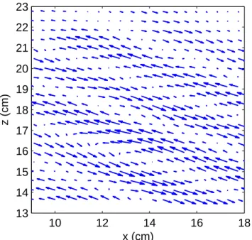
Figure 5 shows the velocity field. As expected, it is parallel to the direction of emission, emphasizing nicely the pure shear structure. Moreover, it clearly attests that iso-phase lines are propagating perpendicularly to the energy propagation. The maximal velocity value mea-sured in that case is 1.8 mm/s, while amplitude displace-ments are of the order of 1 cm.
4.2 Temporal chromaticity
As stated in Sec. 1, monochromatic internal gravity waves are highly desirable for studying, for example, the role of nonlinearities involved in collisions with topography
10 12 14 16 18 13 14 15 16 17 18 19 20 21 22 23 x (cm) z (cm)
Fig. 5 Zoom of the velocity field generated by the generator.
(Ivey and Nokes 1989, Dauxois and Young 1999, Gosti-aux 2006) or with other internal waves (Teoh et al. 1997): the chromaticity quality of the incident beam is there-fore of primary importance. With the present device, as the forcing is itself solution of the wave equation, no har-monics are measurable in the flow. To attest this result, Fig. 6(a) shows a temporal evolution of the horizontal ve-locity at a point situated in the centerline of the beam, 29 cm away from the generator.
First, note that the signal is vanishingly small before starting to increase at t = 30 s. This remark allows to compute the group velocity of the beam. As the genera-tion and measurement points are distant by 29 cm, one gets a group velocity cg ≃ 0.97 cm/s. This value has to
be compared with the theoretical one, cg = λ/(T tan θ),
where T is the excitation period, λ the wavelength of the internal beam and θ the angle of propagation. With λ = 13.2 cm, T = 36 s and θ = 19◦, the expected value
cg= 1.06cm/s compares well with the measurement.
Moreover, one can notice that the transient regime is almost invisible as the wave reaches the measurement area. This allows to consider the forcing of such a wave as a suddenly switched on sinusoid (sinus function con-voluted with a Heaviside distribution), which allows fine comparisons with analytical results using such a forcing (Dauxois and Young 1999).
Once the beam reaches the measurement point, the velocity oscillates at a well defined frequency. The tem-poral spectrum of the wave, plotted in Fig. 6(b), con-firms that the frequency signal is, as expected, imposed by the generator. Moreover, it shows that amplitudes of higher harmonics (see the inset in logarithmic scale) are at least one order of magnitude smaller than the funda-mental one. The emitted beam is thus highly temporally
monochromatic. The latter characteristic allows to fil-ter the velocity field at the excitation frequency in order to reduce measurement noise. The filtering technique is used in Figs. 7 and 8 which present spatial properties of the beam. 0 50 100 150 200 250 −5 0 5 t (sec) U (mm.s −1 ) 0 1 2 3 4 5 6 7 8 0 1 2 3 f/f0 <U> (mm.s −1 ) 0 1 2 3 4 5 6 7 8 10−2 10−1 100 101 a) b) a) b)
Fig. 6 Temporal analysis of the internal waves beam in a point located at 29 cm from the wavemaker and in the middle of the beam. Panel (a) presents the time evolution of the horizontal velocity field, while panel (b) shows the Fourier transform of this signal. Frequencies are renormalized with the excitation one, f0 = 1/T . The inset in panel (b) presents
the spectrum in logarithmic scale.
4.3 Spatial structure of the beam
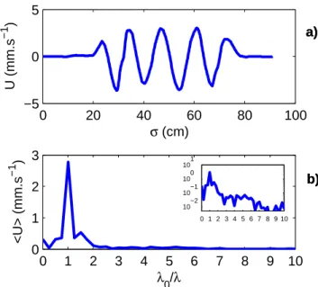
Contrary to optical or acoustic waves, and owing to the unusual dispersion relation (1) of internal waves, tempo-ral monochromatism does not imply any spatial monochro-matism: it is necessary to study them separately. Fig. 7(a) presents a cross section of the horizontal velocity field at 29 cm from the wavemaker. One may easily distinguish slightly more than four wavelengths. Its corresponding wavelength spectrum is shown in Fig. 7(b). The spatial monochromatism of the produced beam is attested by the very well defined peak of the spectrum. Note that a careful study shows that end effects in the horizon-tal y-direction have very little, if no, consequences: one can only detect a very small transverse component of the velocity field.
Finally, Fig. 8 emphasizes that the viscous damping of the beam along its propagation is extremely weak. One can notice the non-dispersive profile of the wave front: the beam does not disperse since it is spatially monochromatic. From this picture, it is possible to get
6 0 1 2 3 4 5 6 7 8 9 10 0 1 2 3 λ0/λ <U> (mm.s −1 ) 0 20 40 60 80 100 −5 0 5 σ (cm) U (mm.s −1 ) 0 1 2 3 4 5 6 7 8 9 10 10−2 10−1 100 101 a) b) a) b)
Fig. 7 Transversal structure of the internal waves beam, 29 cm from the wavemaker. Panel (a) presents the spatial evo-lution of the horizontal velocity field, while panel (b) shows the Fourier transform of this signal. Wavelengths are renor-malized with the excitation one λ0. The inset in panel (b)
presents the spectrum in logarithmic scale.
another reliable estimate of the group velocity. Indeed, by measuring the location difference of the appearance of the velocity U = 1 mm/s or by trying to superpose the first three profiles, one gets cg≃ 38 cm per period i.
e. 1.06 cm/s: the precise theoretical value derived previ-ously.
This generator was used to excite waves up to 1.5 meters away from the region of interest, no apprecia-ble damping was measured at this point. The absence of nonlinear losses may explain this remarkable constancy of the wave amplitude.
0 20 40 60 80 100 120 0 1 2 3 4 s (cm) U (mm.s −1 ) T 2T 3T 4T 5T 6T T 2T 3T 4T 5T 6T T 2T 3T 4T 5T 6T
Fig. 8 Superposition of successive longitudinal profiles of the horizontal velocity after 1, 2, 3, 4, 5 and 6 excitation periods.
5 Conclusion
We have reported the design of a new kind of internal waves generator that imposes a rigid boundary condi-tion compatible with the equacondi-tions governing the agation of plane internal waves. By generating a prop-agating shear, we select a single direction of emission of the waves. The waves emitted are purely monochro-matic, both spatially and temporally, which is of first importance for the study of nonlinear processes involved in internal waves dynamics.
Finally, it is important to emphasize that this exper-imental setup allows to generate any kind of wave form. Not only sinusoidal, but also gaussian beams or more complicated shapes can be easily generated, by modify-ing the camshafts eccentricity appropriately. This pos-sibility opens new perspective for future studies of the dynamics of internal waves in stratified fluids.
Acknowledgements We warmly thank J. Sommeria for help-ful discussions and S. Viboud for help during the experiments. Figure 1(f) was obtained by D. Benielli and J. Sommeria. Comments to the manuscript by Denis Martinand are deeply appreciated. This work has been partially supported by 2005-ANR Project TOPOGI-3D and by the 2006-PATOM CNRS program.
References
1. Benielli D (1995): Excitation param´etrique et
d´eferlement d’ondes internes en fluide stratifi´e, PhD thesis ENS Lyon
2. Benielli D, Sommeria, J (1998): Excitation and break-ing of internal gravity waves by parametric instability. Journal of Fluid Mechanics 374, 117
3. Cacchione D, Wunsch C (1974): Experimental study of internal waves over a slope. Journal of Fluid Mechanics 66, 223
4. Dalziel SB, Hughes GO, Sutherland BR (2000): Whole field density measurements by synthetic schlieren. Ex-periments in Fluids 28, 322
5. Dauxois T, Young, WR (1999): Near-critical reflection of internal waves. Journal of Fluid Mechanics 390, 271 6. Eriksen CC (1998): Internal wave reflection and mixing
at fieberling guyot. Journal of Geophysical Research 103, 2977
7. Fincham A, Delerce G (2000): Advanced optimization of correlation imaging velocimetry algorithms. Experiments in Fluids 29, 13
8. Gerkema T, Lam F-PA, Maas LRM (2004): Internal tides in the Bay of Biscay: conversion rates and seasonal ef-fects. Deep-Sea Research II 51:2995-3008
9. G¨ortler H (1943): Uber eine schwingungserscheinung in flussigkeiten mit stabiler dichteschichtung. Zeitschrift f¨ur angewandte Mathematik und Mechanik 23, 165
10. Gostiaux L, Dauxois T (2006): Internal tides in labora-tory experiments. Submitted to Physics of Fluids 11. Gostiaux L, Dauxois T, Didelle H, Sommeria J, Viboud
S (2006): Quantitative laboratory observation of internal wave reflection on ascending slopes. Physics of Fluids 18, 056602
12. Hill DF (2002): General density gradients in general do-mains: the “two-tank” method revisited. Experiments in Fluids 32, 434
13. Hurley DG (1997): The generation of internal waves by vibrating elliptic cylinders. Part 1. Inviscid solution. Journal of Fluid Mechanics 351, 105
14. Hurley DG, Hood MJ (2001): The generation of inter-nal waves by vibrating elliptic cylinders. Part 3. Angular oscillations and comparison of theory with recent exper-imental observations. Journal of Fluid Mechanics 433, 61
15. Hurley DG, Keady G (1997): The generation of internal waves by vibrating elliptic cylinders. Part 2. Approximate viscous solution. Journal of Fluid Mechanics 351, 119 16. Ivey GN, Nokes RI (1989): Vertical mixing due to the
breaking of critical internal waves on sloping boundaries. Journal of Fluid Mechanics 204, 479
17. Ivey GN, Winters KB, Silva IPDD (2000): Turbulent mixing in a sloping benthic boundary layer energized by internal waves. Journal of Fluid Mechanics 418, 59 18. Lam F-PA, Maas LRM, Gerkema T. (2004): Spatial
structure of tidal and residual currents as observed over the shelf break in the Bay of Biscay. Deep-Sea Research I 51, 10751096
19. Maas LRM, Benielli D, Sommeria J, Lam FPA (1997): Observation of an internal wave attractor in a confined stably stratified fluid. Nature 388, 557
20. McEwan AD (1973): Interactions between internal grav-ity waves and their traumatic effect on a continuous strat-ification. Boundary-Layer Met. 5, 159
21. Mowbray, D.E., Rarity, B.S.H. (1967): A theoretical and experimental investigation of the phase configuration of internal waves of small amplitude in a density-stratified liquid. Journal of Fluid Mechanics 28, 1
22. Oster G (1965): Density Gradients. Scientific American 213, 70
23. Peacock, T., Weidman, P. (2005): The effect of rotation on conical wave beams in a stratified fluid. Experiments in Fluids 39, 32
24. Silva IPDD, Imberger J, Ivey GN (1997): Localized mix-ing due to a breakmix-ing internal wave ray at a slopmix-ing bed. Journal of Fluid Mechanics 350, 1
25. Teoh SG, Imberger J, Ivey GN (1997): Laboratory study of the interactions between two internal wave rays. Jour-nal of Fluid Mechanics 336, 91
26. Thomas NH, Stevenson TN (1972): A similarity solution for viscous internal wave. Journal of Fluid Mechanics 54, 495
27. Thorpe SA (2005): The Turbulent Ocean. Cambridge University Press
28. Voisin B (2003): Limit states of internal wave beams. Journal of Fluid Mechanics 496, 243