HAL Id: hal-01745418
https://hal.archives-ouvertes.fr/hal-01745418
Submitted on 28 Mar 2018
HAL is a multi-disciplinary open access
archive for the deposit and dissemination of
sci-entific research documents, whether they are
pub-lished or not. The documents may come from
teaching and research institutions in France or
abroad, or from public or private research centers.
L’archive ouverte pluridisciplinaire HAL, est
destinée au dépôt et à la diffusion de documents
scientifiques de niveau recherche, publiés ou non,
émanant des établissements d’enseignement et de
recherche français ou étrangers, des laboratoires
publics ou privés.
)/28 nm FDSOI CMOS Technology
Jean-Michel Portal, Marc Bocquet, Santhosh Onkaraiah, Mathieu Moreau,
Hassen Aziza, Damien Deleruyelle, Kholdoun Torki, Elisa Vianello, Alexandre
Levisse, Bastien Giraud, et al.
To cite this version:
Jean-Michel Portal, Marc Bocquet, Santhosh Onkaraiah, Mathieu Moreau, Hassen Aziza, et al..
De-sign and Simulation of a 128 kb Embedded Nonvolatile Memory Based on a Hybrid RRAM (HfO_2
)/28 nm FDSOI CMOS Technology. IEEE Transactions on Nanotechnology, Institute of Electrical
and Electronics Engineers, 2017, 16, pp.677 - 686. �10.1109/TNANO.2017.2703985�. �hal-01745418�
Abstract— Emerging Non-Volatile Memories (NVM) based on
resistive switching mechanism such as RRAM are under intense R&D investigation by both academics and industries. They provide high write/read speed, low power and good endurance
(e.g. >1012) beyond mainstream NVMs, enabling them to be a
good candidate for Flash replacement in Micro-Controller Unit (MCU). This replacement could significantly decrease the power consumption and the integration cost on advanced CMOS nodes.
This paper presents firstly the HfO2 based RRAM technology
and the associated compact model, which includes related physics and model card fitting experimental electrical characterizations. The 128kb memory architecture based on RRAM technology and 28nm FDSOI CMOS core process is presented with a bottom-up approach, starting from the bit-cell definition up to the complete memory architecture implementation. The key points of the architecture are the use of standard logic MOS exclusively, avoiding any high voltage MOS usage, program/verify procedure to mitigate cycle to cycle (C2C) variability issue and direct bit-cell read access for characterization purpose. The proposed architecture is validated using post-layout simulations on MOS and RRAM corner cases.
Index Terms—Embedded non-volatile memory, memory
architecture, resistive switching memory, RRAM,
I. INTRODUCTION
The non-volatile Memory (NVM) development is driven by
Manuscript received XXX, 2016; revised XXX; accepted XXX. This work was supported in part by the French national projects ANR-DIPMEM.
Jean-Michel Portal, Marc Bocquet, Santhosh Onkaraiah, Mathieu Moreau and Hassen Aziza are with Aix-Marseille University, IM2NP – UMR CNRS 7334, Marseille, France (Corresponding author: tel: +33413554011, fax: +33491119711, email: [email protected]).
Kholdoun Torki is with CMP, Univ. Grenoble Alpes, F-38000 Grenoble, France;
Elisa Vianello, Alexandre Levisse, Bastien Giraud, Olivier Thomas and Fabien Clermidy are with Univ. Grenoble Alpes, F-38000 Grenoble, France; CEA, LETI, MINATEC Campus, F-38054 Grenoble, France
Damien Deleruyelle is with Institut des Nanotechnologies de Lyon (INL), CNRS UMR5270, 69621 Villeurbanne Cedex
Copyright (c) 2012 IEEE. Personal use of this material is permitted. However, permission to use this material for any other purposes must be obtained from the IEEE by sending an email to [email protected].
two strong markets: the high performance, high density, high capacity memories for computation in servers, and the low energy, low cost embedded-memories devoted to autonomous connected nodes. The growth of these two markets is strongly related to each other and is at the basis of Internet of Things market.
High performance computing applications for servers require high quantities of NVM [1] in order to store and process tremendous amount of data generated by the autonomous connected nodes that are spread in the environment [2]. To this aim, high performance Volatile and Non-Volatile memories are used. In classic computing, the first elements of memory hierarchy are the volatile memories: SRAM and DRAM. The DRAM memory is used as a buffer between NVM and SRAM cache memories. At the end of the hierarchy are NVM memories HDD [3] and NAND Flash technologies [4]. The main constraints of these memories are (i) overall power consumption (from the DRAM refreshment to the NVM programming operations), (ii) communication cost between processing units and memories, and (iii) production costs per bit.
Embedded memories for autonomous connected objects are more focused in reducing energy consumption and the overall chip cost. These device operations are based on classical memory hierarchy. Von Neumann or Harvard architectures are considered. SRAM memories are used to store the variables while NVM is used to store the instruction code. Embedded NVM are based on NOR flash technologies [5] [6] [7] down to 40nm commercial CMOS technologies.
For both server applications (standalone NVM) and autonomous connected nodes (embedded NVM), scaling down the technology nodes is a real struggle. NAND flash technology complexity (air gap [8], vertical stacking [9], multiple patterning [10]) and production costs are becoming unaffordable. On the embedded side, NOR flash is facing extremely complex structure [11], and the co-integration with advanced CMOS nodes leads to reliability issues due to the high voltages needed for NVM programming operations. Moreover, scaling down floating gate technologies leads to
Design and Simulation of a 128kb Embedded
Non-Volatile Memory based on a Hybrid
RRAM (HfO
2
) / 28nm FDSOI CMOS
Technology
Jean-Michel Portal, Marc Bocquet, Santhosh Onkaraiah, Mathieu Moreau, Hassen Aziza, Damien
Deleruyelle, Kholdoun Torki, Elisa Vianello, Alexandre Levisse, Bastien Giraud, Olivier Thomas,
reduced endurance and retention [12].
In order to continue the scaling of NVM technologies, for both Embedded and Standalone applications, emerging resistive switching technologies (i.e. RRAM) are extensively investigated [13] because of their Back End of Line (BEoL) compatible structure and their high scalability [14]. Among all the RRAM technologies, the Oxide-Based RRAM (OxRAM), because of their simple stack structure, fast switching, and common material appear as a promising solution for Flash memories replacement [15]. Several metal oxides can be used to obtain the OxRAM behavior such as AlOx, NiOx, TaOx, TiOx or HfOx [16] [17] [18] [19]. Integrating RRAMs as Flash memories replacement can be a solution either for Standalone Memories or for Embedded Memories. In the context of Standalone Memories, the supporting CMOS technology is totally dedicated to the memory integration and, as a consequence, the associated CMOS technology does not suffer from the memory requirements. In the context of Embedded Memories, CMOS technology is a limitation due to integration severe constraints. For example, in NOR Flash integration at advanced CMOS nodes, High Voltage Thick Oxide Transistors are integrated at the cost of additional masks, higher thermal budget and higher occupied area [20]. The co-integration of RRAM at sub 30nm CMOS technologies leads to reliability issues on the Thin Oxide Transistors and is usually solved by using the IO transistors (thicker gate oxide process with no impact on the thin oxide transistor performances) [21]. The direct impact is a higher maximum voltage, but also a larger footprint (up to 15 times for an equivalent drive). Several Embedded RRAM Memories are presented considering thick gate oxide transistors, in [22] a 4Mb HfO2-based RRAM memory in 180nm CMOS technology with write verify technic is demonstrated, in [23] a 4Mb embedded RRAM memory is demonstrated with process variation control circuits in 130nm CMOS technology. In [24] a 4Mb macro using a unipolar RRAM is embedded in 65nm CMOS technology. A 1Mb RRAM memory embedded 28nm bulk CMOS is demonstrated in [25] with write assist circuits. However, in these papers the reliability issue on MOS transistors during programming operations and during the forming step is not considered. Others studies using thick oxide transistors and Conductive Bridge Random Access Memories (CBRAM) [21] or Phase Change Memories (PCM) [26] are reported.
In [27], a testchip with 28nm thin-gate oxide bitcells was presented and the MOS transistors reliability is shown for a 3V programming voltage.
This paper presents the architecture of an embedded 128kb memory cut based on a hybrid RRAM (HfO2) and thin-gate
oxide 28nm Fully Depleted Silicon On Insulator (FDSOI) CMOS technology suitable for NOR Flash replacement. Validation of the proposed architecture is performed through post-layout simulation by using RRAM compact model calibrated on CEA-Leti RRAM samples [28] and implemented under transistor-level simulator Eldo [29] and CMOS 28nm FDSOI design kit from STMicroelectronics.
The rest of the paper is organized as follows: In the next section, the RRAM technology is briefly introduced together with the compact model calibrated on state of the art devices. In section III, the bit-cell and the memory array organization are described with the different modes of operation (FORMING/SET, RESET and READ). Section IV is dedicated to the full memory macro-cell description, including peripheral circuits, addressing hierarchy and scheduler. The validation of the macro-cell through simulation is presented in Section V. Finally, Section VI gives some concluding remarks and highlights on the proposed embedded memory.
II. RRAMOVERVIEW:TECHNOLOGY AND COMPACT MODEL
RRAM based on HfO2 are studied as part of the bit-cell of
the proposed memory architecture. The RRAM stack is composed of a 5 nm thick HfO2 resistive switching layer
embedded in-between a TiN/Ti Top Electrode (TE) and a TiN Bottom Electrode (BE). The resistive switching layers are deposited by Atomic Layer Deposition (ALD), whereas the metallic electrodes are deposited by Physical Vapor Deposition (PVD) [28].
RRAM modeling used in this study is based on the work presented in [30]. This approach relies on electric field-induced creation/destruction of oxygen vacancies within the switching layer. The model enables continuous accounting for FORMING, SET and RESET operations into a single master equation in which the resistance is controlled by the radius of a conductive filament (namely rCF).
After calibration, the model satisfactorily matches quasi-static and dynamic experimental data measured on actual HfO2-based memory elements. Moreover, to account for the
variability of RRAM technology, two corners cases were simulated. They include the two extreme behaviors observed experimentally: one favoring the SET mechanism and slowing the RESET, and the other being the exact opposite.
The Fig.1 show the quasi-static behavior of RRAM devices and the good modeling correlation. The corners encompass the full range of features that ensure to take into account the worst case of FORMING, SET and RESET.
Figure 1: Experimental I(V) characteristics for Electroforming, Set, and Reset measured on a large number of memory elements reflecting the device-to-device variability presented in [28] and simulation results including corners definition.
Figure 2: Experimental (a) switching time for Forming, Set and Reset operations as a function of voltage and (b) RHRS as a function of stop voltage during Reset operation presented in [28] and corresponding simulation results.
The Fig.2.a describes the dependence of the switching time according to the amplitude of the programming pulse voltage. It is important to note that rapid operations – low consumptions – need higher CMOS standard voltage. Furthermore, the Fig.2.b. underlines the interest of high voltage applied during the RESET to ensure a high resistance value. These two central behaviors are perfectly captured by the model implemented and extreme behaviors are included within in the corner simulations.
III. BIT-CELL AND MEMORY ARRAY ORGANIZATION
In this section, the bit-cell structure is detailed together with memory array organization. Based on the array arrangement, biasing conditions for selected and unselected cells in the array are discussed for the different modes of operation. A. Bit-cell structure
The bit-cell is based on a 2T1R structure [31], as described in Fig.3.a and exhibits one NMOS and one PMOS to access the Top Electrode (TE) of the RRAM, whereas the Bottom Electrode (BE) is connected to the Reset Line (RL). In addition to the classical Bit-Line (BL) and Word-Line (WL), two others lines are present namely Reset-Line (RL) and
Set-Line (SL).
Figure 3: (a) Schematic view of the bit-cell with 2T1R and four access lines (BL, WL, SL and RL) (b) Layout of the bit-cell, with a RRAM element introduces in the Metal Insulator Metal (MIM) stack to avoid CMOS process modification at the cost of large cell area.
Figure 4: (a) FORMING/SET are performed through the PMOS, SL is set to the positive operation voltage, RL is grounded whereas NMOS transistor is off (b) RESET is performed through NMOS, RL is set to the positive operation voltage, BL is grounded whereas PMOS transistor is off. For READ operation, BL is set to the read voltage and RL is grounded, here also the PMOS transistor is off. To reduce voltage degradation, two different paths are used through PMOS and NMOS, in order to fit the bipolar behavior of the RRAM.
As depicted Fig.3.b, to avoid any CMOS core process modification, the RRAM elements are introduced in the Metal Insulator Metal (MIM) stack between the first and second 8x metallization level in place of the decoupling capacitance. On one hand, this solution is fully compatible with the standard CMOS 28nm FDSOI process flow but on the other hand this integration scheme is achieved at the cost of a larger RRAM foot-print on the upper metallization level.
The additional lines RL and SL are used to perform FORMING/SET and RESET/READ operations on two different paths, as illustrated Fig.4. Doing so FORMING/SET voltages are applied on the top electrode of the RRAM through the PMOS (Fig.4.a), whereas ground (gnd) is applied on the top-electrode through a NMOS and RESET voltage is applied on the RL during a RESET operation (Fig.4.b). With this scheme, degradation of the voltage level for the different operations is reduced, since positive voltages are applied through PMOS transistor whereas ground voltages are applied through NMOS. Moreover, the compliance current, during FORMING / SET operations, is defined by the sizing of the PMOS transistor and by the VDDM biasing. Given that the
current flowing through the cell during the RESET operation must be above the FORMING / SET current, the NMOS transistor has to be larger than the PMOS for an equivalent biasing. (a) (b) WL SL BL RL TE BE BL WL SL RL TE BE VDDM (a) (b)
B. Memory array organization
The arrangement of the memory array is given in Fig.5.a with the schematic view and Fig.5.b with the corresponding layout view. The RL and WL lines are shared per row whereas BL and SL are shared per column. To access a cell for a given operation, biasing of all the four access lines is mandatory, whereas inhibition voltages must be applied on unselected cells. Depending, on the operation unselected cells are inhibited by turning OFF the access transistor (NMOS and PMOS) with VGS below the threshold voltage or by having a
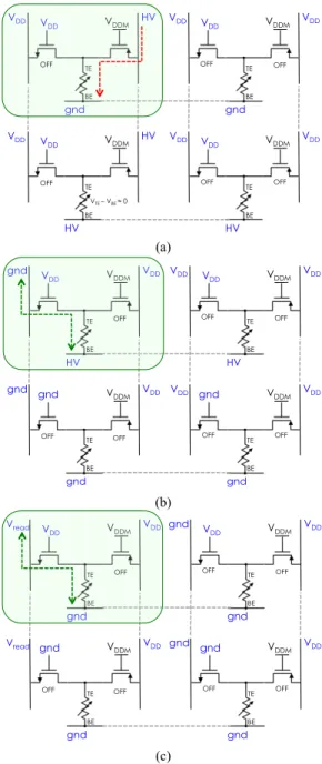
voltage difference on the RRAM close to zero volt. Fig.6 summarizes the biasing of the different access lines for four cases: selected bit-cell, unselected bit-cell on the same row, unselected bit-cell on the same column, unselected bit-cell on the rest of the array without any common lines with the selected cell. Three potentials are used, VDD equal to VDDM in
the array, ground (gnd) and a high voltage (HV). HV takes a
Figure 5: (a) Schematic view of a two by two bit-cell array (b) Layout view of a two by two bit-cell array. SL and BL lines are shared in column; RL and WL are shared in row.
value close to 2.5×VDDM for the FORMING operations and a
value close to 2×VDDM for the SET and RESET operations.
Fig.6 depicts a single cell access, but this memory array organization enables to perform all the programming operations by selecting an entire or partial row or a full or partial array. This feature offers the capability to have the best compromise between speed and consumption.
In the proposed memory macro-cell, the array is defined by
the bank size. A bank is composed of 1024 cells organized on 32 rows per 32 columns, in other words, 32 words of 32 bits. To program a word, a RESET operation is first performed on the bits to reset and followed by a SET operation on the remaining bits of the word. Similarly to NOR Flash memory, two programming phases are used to write a word. But, in our case, both operations are selective contrary to Flash memory, where erase operation is applied to all bits in the word followed by a selective write operation.
Figure 6: (a) Array biasing condition for a FORMING/SET operation performed on a single cell (b) Array biasing condition for a RESET operation performed on a single cell (c) Array biasing condition for a READ operation performed on a single cell. Biasing condition of the selected cell can be extended to any cells on a row to perform parallel operations. Biasing conditions can also be applied on the full array to perform global operation.
(a) (b) (a) (b) (c) VDD V DD HV HV TE BE VDDM VDD VDD VDD HV TE BE VDDM VDD V DD HV gnd TE BE VDDM VDD VDD VDD gnd TE BE VDDM OFF OFF OFF OFF OFF OFF VTE – VBE ≈ 0 gnd gnd VDD gnd TE BE VDDM VDD gnd VDD gnd TE BE VDDM gnd VDD VDD HV TE BE VDDM VDD VDD VDD HV TE BE VDDM OFF OFF OFF OFF OFF OFF OFF Vread gnd VDD gnd TE BE VDDM gnd gnd VDD gnd TE BE VDDM Vread V DD VDD gnd TE BE VDDM gnd VDD VDD gnd TE BE VDDM OFF OFF OFF OFF OFF OFF OFF
IV. FULL MACRO-CELL ARCHITECTURE OVERVIEW
In this section the full macro-cell architecture is detailed, starting with the peripheral blocks to address the bank array, up to the full macro-cell hierarchy including scheduler finite state machine to generate timing and internal signals. It is worth to note that the macro-cell communication bus is fully compatible with AMBA 3 AHB lite protocol [32].
A. Peripheral block description
The macro-cell architecture is massively multi-bank, thus all peripheral circuits to program and read the content of the bit-cells are introduced at bank level. In this subsection, level-shifters used for programming operations as well as sense amplifier used for reading operation are detailed.
Banks are powered with two power supply VDD=VDDana and a
higher voltage for FORMING/SET/RESET operations named HV. During programming operation, level shifters are used to drive HV on RL and SL access lines, while classic buffers are used to drive gnd/VDDana on BL and WL access
lines. Table I gives a summary of possible biasing of the different access lines.
Figure 7: (a) Schematic view of the level shifter used to drive SL access line (b) Layout view of the level shifter used to drive SL access line. The SL level shifter output swing is defined between VDDM and HV. The level shifter input
is controlled with standard voltage logic (VDD domain).
The architecture of level shifters acting on SL and RL are represented in Fig.7 and Fig.8 respectively with their schematic and layout views. Level shifter structures are designed with cascade MOS since the voltage difference
between any MOS transistor nodes has to be below or equal to VDD to ensure reliability and avoid gate-oxide breakdown.
Only bit-cells on a common row are activated at a time during programming operation, thus since SL level shifters are shared per column, they only have to drive single cell FORMING/SET compliance current, limiting the sizing of their output stage.
On the contrary, RL level shifters are shared per row, thus during a RESET operation, they may drive up to the 32 bit-cells of the addressed word. Thus, the sizing of the RL level shifter output stage is able to drive 32 times the current of a single cell. It is to be noted on the layout view of the RL level shifter (Fig.8.b), that a single output buffer is multiplied 32 times to form the complete output stage. Similar to the SL level shifter, the input of the RL level shifter is driven by logic gate biased in the VDD domain.
Figure 8: (a) Schematic view of the level shifter used to drive RL access line (b) Layout view of the level shifter used to drive RL access line. The RL level shifter output swing is defined between gnd and HV. The level shifter input is controlled with standard voltage logic (VDD domain).
In order to sense the value of each bit-cells, sense amplifiers are added on top of the corresponding columns. Applying a current IREAD through the resistive element and comparing the
resulting voltage VREAD with a voltage reference VREF gives
the logic value of the bit-cell. IREAD is generated thanks to a
Wilson current mirror structure. An operational full swing amplifier is used to discriminate between VREAD and VREF.
Since, RRAM technology is still in development, the reference voltage VREF is provided externally for
characterization purpose. Indeed, by trimming VREF value,
knowing IREAD, it is possible to extract the resistance value of
all the bit-cells in the array and thus extract Low Resistance State (LRS) and High Resistance State (HRS) distributions on chip. Doing so at the end of the characterization procedure, VREF value is set between the voltage distribution
corresponding to LRS and HRS distributions. Moreover, an external pad gives a direct access to the bit-cell content to extract RRAM resistance value in order to verify the value extracted from VREF trimming. This pad can be connected to
the sense amplifier of the first column (BL0) of each bank.
TABLEI
VOLTAGE SWING ON THE BIT-CELL ACCESS LINES
Access lines Voltage swing WL gnd to VDDana BL gnd to VDDana SL VDDana to HV RL gnd to HV (a) (b)
(a) (b)
Figure 9: (a) Schematic view of the sensing circuitry connected to a bit-line including read current generation, output direct access and operational amplifier (b) Layout view of the 32 sensing circuitry associated to the 32 bit-line of a single bank.
Fig.9.a illustrates the sense amplifier architecture, including CDMA standing for Current Direct Memory Access to provide IOUT on the first column of each bank from an external
PAD for characterization purpose, doing so internal current mirror is disconnected. Finally, it is worth noting that internal current mirror as well as operational amplifier can be disconnected from VDD when no sensing operation is required.
The layout of the sense amplifier together with current mirror is given Fig.9.b.
B. Bank organization and addressing hierarchy
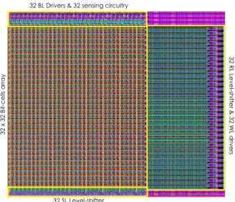
Figure 10: Layout view of a full bank including a 32 by 32 bit-cells with surrounding peripherals circuits, i.e. 32 SL level shifters below the array, 32 BL drivers and 2 sensing circuitry on top of the array and 32 RL level shifter and 32 WL drivers on the right of the array.
A bank is composed of 32 by 32 bit-cells to avoid voltage drop on the access line. Indeed, since the whole circuit is designed with GO1 devices the voltage budget is limited, especially during the FORMING steps. Thus, all peripheral circuits, i.e. level shifters, sensing circuitry are implemented at
bank level, as depicted Fig.10 with the layout view. Moreover, addressing signal gates all control signals at bank level. Thus, unselected bank are completely inactive, with no internal signal change, preventing any disturb or extra power-consumption.
For the selected bank an acknowledgement signal is generated to properly apply all control signal and to avoid any temporal drift between signals due to hierarchy routing. The top-analog circuit is divided into four sectors of eight pages and each page contains four banks. Control signals, generated by the digital scheduler, are enabled at each level of the hierarchy. Moreover, buffers are inserted on all input signals (data, address and control) and tri-state buffer are inserted on the data-out signals, to prevent delay issue.
Figure 11: Layout view of the full macro-cell with top analog (right) and scheduler (left).
C. Scheduler description
The scheduler is a Finite State Machine (FSM) compatible with AMBA 3 AHB lite protocol, which generates all necessary timing and internal signal to drive the top analog circuit. The timing can be trimmed since a programmable timer gives the time reference. Indeed, the targeted bus clock is in the range of a few ten’s of MHz, in other words a few hundreds of ‘ns’ period, while FORMING/RESET/SET operations are in a range of ‘ms’ to ‘µs’ depending on the targeted HV voltage and RRAM technology variability. Thus, to enhance yield, timing has to be programmable in order to fit the voltage/duration dependency of the RRAM technology for the outlier cells of the memory array.
The scheduler states are Ready, Read, Write. The Write state is decomposed in a second FSM, since a write operation can be of two kinds FORMING or RESET/SET. Moreover, a write/verify procedure is embedded in the scheduler. After a write, which is a RESET operation followed by a SET operation, a read is performed and data are compared to data in, in case of mismatch, up to 10 cycles of RESET/SET operations can be applied. After 10 cycles, if Write operation still fails the HRESP signal indicates an error. This write/verify procedure has been implemented to tackle cycle-to-cycle variability of the RRAM technology.
The full layout of the 128kb Non-Volatile Memory based on a Hybrid RRAM (HfO2) / 28nm FDSOI CMOS Technology is given Fig.11 and its main simulated features are summarized Table II.
(a) (b) 32 R L L e ve l-s hift e r & 3 2 WL d riv e rs 32 SL Level-shifter 32 BL Drivers & 32 sensing circuitry
32 x 32 B it-ce lls a rra y Sch e d ul e r Sector Page Bank
TABLEII MACROCELL SUMMARY
FEATURES VALUE
CAPACITY 128 KB
SECTOR 32 KB
PROCESS 28 NM FDSOICMOS&HFO2RRAM
CHIP SIZE 2.52 MM ×1.03 MM =2.6 MM2
POWER SUPPLY (TYP.) VDDDIG=1V,VDDANA=1.2V,
HVFORMING =2.8V/HVSET/RESET=2.4V
BUS CLOCK 25MHZ
READ/WRITE SIZE 32 BITS
WRITE THROUGHPUT (TYP.) 114MB/S
READ THROUGHPUT (TYP.) 400MB/S
V. FULL MACRO-CELL VALIDATION
Figure 12: Simulation results (corner Typical) of the FORMING process for a full bank. Current through RRAM of the cell0,0 (Word 0, Bit 0) and
of the cell31,31 (Word 31, Bit 31), CF radius evolution during forming, as
well as access-line voltage to the cell0,0 and cell31,31 are plotted. In this section, the 128kb Non Volatile Memory circuit is validated through transistor-level simulations. To demonstrate the functionality of the proposed architecture, a post-layout simulation of the selected bank (corner typical) is performed with the following sequence:
• FORMING sequentially each addressed word within a given bank
• READ sequentially each addressed word to confirm FORMING operation, i.e. LRS value for all bit-cells in the bank.
• PROGRAM the full bank with a checkerboard (0101.., 1010..) pattern by addressing each word sequentially • READ sequentially each addressed word of the bank to
retrieve the checkerboard pattern
• PROGRAM the same full bank with an inverse checkerboard pattern by addressing each word sequentially
• READ sequentially each addressed word of the bank to retrieve the inverse checkerboard pattern.
Fig.12 shows the FORMING operation of a full bank, all the words are sequentially formed, it is worth to note that the FORMING process duration for a word is 100µs, thus for a full bank, it represents 3.2ms. The Fig.12 highlights the voltage, current and Conductive Filament (CF) radius variation for the first bit-cell of the first word (Cell0,0) and for the last cell of the last word (Cell31,31). For all the bit-cell, the compliance current during FORMING is set to 62µA, representing an overall current of nearly 2mA for a full word.
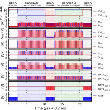
Figure 13: Simulation results (corner Typical) of the full PROGRAM/READ process for a full bank. CF radius evolution of the cell0,0 RRAM (Word 0, Bit
0) and of the cell31,31 RRAM (Word 31, Bit 31), during PROGRAM&READ,
as well as access-line voltage to the cell0,0 and cell31,31 are plotted. Finally,
the similarity of the DATA_IN and DATA_OUT values shows the success of PROGRAM and READ operations.
The evolution of the CF radius clearly shows the FORMING
operation. The biasing conditions extracted from the simulation are:
• All the BL and WL remains to VDDana=1.2V during the FORMING process,
• SL is set to HVFORMING=2.75V, instead of 2.8V due to voltage drop in the SL level-shifter,
• RL is set to 5mV, instead of ground due to voltage drop in the RL level-shifter for the selected word, whereas it is set to HVFORMING for unselected words.
Thus the selected RRAM are biased to 2.75V during FORMING. One can notice a very low leakage on the already formed cell of 0.76µA (see ICELL (cell0,0) during the
FORMING of the word 31 in Fig.12).
Fig.13 shows simulation results for the overall READ/PROGRAM process on a bank (READ to verify FORMING, PROGRAM checkerboard pattern, READ to
verify checkerboard pattern, PROGRAM inverse checkerboard pattern, READ to verify inverse checkerboard pattern). Functionality is validated, since the programmed patterns are successfully read.
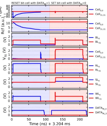
Figure 14: Simulation results (corner Typical) of a PROGRAM operation on cell0,0. Current and CF radius evolution of the cell0,0 RRAM (Word 0, Bit 0)
and of the cell31,31 RRAM (Word 31, Bit 31), during PROGRAM, as well as
access-line voltage to the cell0,0 and cell31,31 are plotted. The program
operation is composed of two steps, RESET/SET.
Fig.14 and Fig.15 highlight respectively a PROGRAM operation and a READ operation. The PROGRAM operation is divided into two steps, in a first step bit-cells corresponding to DATA_IN=’1’ are RESET, whereas in a second step bit-cells corresponding to DATA_IN=’0’ are SET. On Fig.14 DATA_IN0=’1’, thus the cell0,0 is RESET, with a current of
87µA for a voltage on the RRAM of 2.32-0.11 = 2.21V. In the SET step, the cell remains unchanged. Each steps, RESET and SET, takes 80ns for a global PROGRAM time of 170ns per word. Global current consumption is in a range of 1.5mA (SET all the cell) to 2.9mA (RESET all the cell). It is important to notice that the RESET current, as shown in Fig.14, is not constant during the RESET phase. Fig.15 exhibits the two steps of a READ operation, in the first step the current source is enabled to pre-charge the bit-line for 40ns, during the second step the sense amplifier is activated for 2ns to differentiate between HRS and LRS state. The current through the cell during the READ operation is below 2µA. The READ operation duration together with the voltage on the RRAM (worst case 0.8V for a HRS RRAM) allow to avoid any disturb on the cell. This assumption is validated since there is no CF radius change during the READ process presented Fig.15.
The same simulations are performed for the corner cases obtained from the worst-case measurements on the RRAM cell as depicted in Section II together with the SS corner of the CMOS core process. The Fig.16. summarizes the time and energy per cell for different operations, comparing typical (CMOS & RRAM TT) and worst-case results using the corners case (CMOS SS & RRAM corner Slow FORMING/SET and Slow-corner RESET) for the nominal voltages, defined as V1 (HVFORMING=2.8V, HVSET/RESET=2.4V)
and for two others voltages V2 (HVFORMING=3.0V,
HVSET/RESET=2.6V) and V3 (HVFORMING=3.2V,
HVSET/RESET=2.8V).
Figure 15: Simulation results (corner Typical) of a READ operation for a full word. CF radius evolution of the cell0,0 RRAM (Word 0, Bit 0) and of the
cell31,31 RRAM (Word 31, Bit 31), during PROGRAM&READ, as well as
access-line voltage to the cell0,0 and cell31,31 are plotted. Pre-charge and sense
phase are detailed.
To guarantee the functionality of the macro-cell in the worst-case scenarios, timing has to be adapted, due to the voltage/timing characteristic of the RRAM. Doing so for nominal voltage configuration, timings and energy per cell are strongly degraded versus typical simulation as represented Fig.16 (Typical (V1) versus Corners (V1)). To recover typical
results at nominal voltages for worst-case scenarios, voltages have to be increased as represented Fig.16 by V2 and V3
voltage sets. However, the maximal stress voltage defined as gate/source or gate/drain voltage ramps up to 1.8V for
Figure 16: Operation duration and energy per cell for typical and corners cases, for 3 different voltage sets.
FORMING and 1.4V for SET/RESET with set V2 and
respectively 2V and 1.6V with set V3. These voltages remain
acceptable for the FDSOI 28nm standard logic CMOS technology.
VI. CONCLUSION
In this paper, a full 128kb Embedded Non-Volatile Memory based on a Hybrid RRAM (HfO2) & 28nm FDSOI CMOS
Technology is presented. The key points of the architecture are the use of standard logic MOS exclusively, avoiding any high voltage MOS usage, program/verify procedure to
mitigate cycle to cycle (C2C) variability and direct bit-cell read access for characterization purpose. This architecture
has been fully validated through an extensive set of post-layout simulations at different voltage levels and using typical and the most pessimistic corners (MOS SS and RRAM worst FORMING/SET and RESET corners). The memory is
functional at all corners for the different set of voltages owing to the time/voltage dependencies of RRAM.
Moreover, it is interesting to note that the best efficiency is achieved with higher voltages but this track of optimization must be carefully used considering reliability issue of the standard logic MOS devices.
VII. REFERENCES
[1] C. Lynch, "Big data: How do your data grow?," Nature, vol. 455, pp. 28-29, 2008.
[2] J. Gubbia, R. Buyyab, S. Marusica and M. Palaniswamia, "Internet of Things (IoT): A vision, architectural elements, and future directions,"
Future Generation Computer Systems (FGCS), vol. 29, pp. 1645-1660,
2013.
[3] Y. Shiroishi, K. Fukuda, I. Tagawa, H. Iwasaki, S. Takenoiri, H. Tanaka, H. Mutoh and N. Yoshikawa, "Future Options for HDD Storage," IEEE Transactions on Magnetics, vol. 45, pp. 3816-3822, 2009.
[4] M. Helm, J.-K. Park, A. Ghalam, J. Guo, C. W. Ha, C. Hu, H. Kim, K. Kavalipurapu, E. Lee, A. Mohammadzadeh, D. Nguyen, V. Patel, T. Pekny, B. Saiki, D. Song, J. Tsai, V. Viajedor, L. Vu, T. Wong, J. H. Yun, R. Ghodsi, A. D'Alessandro, D. D. Cicco and V. Moschiano, "A 128Gb MLC NAND-Flash device using 16nm planar cell," IEEE
International Solid-State Circuits Conference Digest of Technical Papers (ISSCC), pp. 326-327, 2014.
[5] T. Ogura, M. Mihara, Y. Kawajiri, K. Kobayashi, S. Shimizu, S. Shukuri, N. Ajika and M. Nakashima, "A 90nm Floating Gate "B4-Flash" Memory Technology- Breakthrough of the Gate Length Limitation on NOR Flash Memory," IEEE International Memory
Workshop (IMW), pp. 1-2, 2009.
[6] S. -P. Sim, K. S. Kim, H. K. Lee, J. I. Han, W. H. Kwon, J. H. Han, B. Y. Lee, C. Jung, J. H. Park, D. J. Kim, D. H. Jang, W. H. Lee, C. Park and K. Kim, "Fully 3-Dimensional NOR Flash Cell with Recessed Channel and Cylindrical Floating Gate - A Scaling Direction for 65nm and Beyond," IEEE Symposium on VLSI Technology Digest of
Technical Papers., pp. 17-18, 2006.
[7] R. Fastow, R. Banerjee, P. Bjeletich, A. Brand, H. Chao, J. Gorman, X. Guo, J. B. Heng, N. Koenigsfeld, S. Ma, A. Masad, S. Soss and B. J. Woo, "A 45nm NOR Flash Technology with Self-Aligned Contacts and 0.024µm2 Cell Size for Multi-level Applications," IEEE
International Symposium on VLSI Technology, Systems and Applications (VLSI-TSA), pp. 81-82, 2008.
[8] J. Seo, K. Han, T. Youn, H.-E. Heo, S. Jang, J. Kim, H. Yoo, J. Hwang, C. Yang, H. Lee, B. Kim, E. Choi, K. Noh, B. Lee, B. Lee, H. Chang, S. Park, K. Ahn, S. Lee, J. Kim and S. Lee, "Highly reliable M1X MLC NAND flash memory cell with novel active air-gap and p+ poly process integration technologies," IEEE International Electron
Devices Meeting (IEDM), pp. 3.6.1-3.6.4, 2013.
[9] K.-T. Park, S. Nam, D. Kim, P. Kwak, D. Lee, Y.-H. Choi, M.-H. Choi, D.-H. Kwak, D.-H. Kim, M.-S. Kim, H.-W. Park, S.-W. Shim, K.-M. Kang, S.-W. Park, K. Lee, H.-J. Yoon, K. Ko, D.-K. Shim, Y.-L. Ahn, J. Ryu, D. Kim, K. Yun, J. Kwon, S. Shin, D.-S. Byeon, K. Choi, J.-M. Han, K.-H. Kyung, J.-H. Choi and k. Kim, "Three-Dimensional 128 Gb MLC Vertical nand Flash Memory With 24-WL Stacked Layers and 50 MB/s High-Speed Programming," IEEE
Journal of Solid-State Circuits (JSSC), vol. 50, pp. 204-213, 2015.
[10] F. G. Pikus and A. Torres, "Advanced multi-patterning and hybrid lithography techniques," IEEE Asia and South Pacific Design
Automation Conference (ASP-DAC), pp. 611-616, 2016.
[11] N. Do, "Scaling of split-gate flash memory and its adoption in modern embedded non-volatile applications," IEEE International Conference
on IC Design and Technology (ICICDT), pp. 1-4, 2016.
[12] L. M. Grupp, J. D. Davis and S. Swanson, "The bleak future of NAND flash memory," Proceedings of the 10th USENIX conference on File
and Storage Technologies FAST, p. 2, 2012.
[13] F. Clermidy, N. Jovanovic, S. Onkaraiah, H. Oucheikh, O. Thomas, O. Turkyilmaz, E. Vianello, J.-M. Portal and M. Bocquet, "Resistive memories: Which applications?," IEEE Design, Automation & Test in
Europe Conference & Exhibition (DATE), 2014.
[14] S.-H. Lee, "Scaling trends and challenges of advanced memory technology," IEEE International Symposium on VLSI Technology,
Systems and Application (VLSI-TSA), 2014.
[15] A. Benoist, S. Blonkowski, S. Jeannot, S. Denorme, J. Damiens, J. Berger, P. Candelier, E. Vianello, H. Grampeix, J. F. Nodin, E. Jalaguier, L. Perniola and B. Allard, "Advanced CMOS Resistive RAM Solution as Embedded Non-Volatile Memory," IEEE
International Reliability Physics Symposium (IRPS), pp. 2E.6.1 -
2E.6.5, 2014.
[16] L. Goux, P. Czarnecki, Y. Y. Chen, L. Pantisano, X. P. Wang, R. Degraeve, B. Govoreanu, M. Jurczak, D. J. Wouters and L. Altimime, "Evidences of oxygen-mediated resistive-switching mechanism in TiN\HfO2\Pt cells," Applied Physics Letters, pp. 97(24):243509 - 243509-3, 2011.
[17] Y. Wu, B. Lee and H. -S. P. Wong, "Al2O3-based RRAM using atomic layer deposition (ALD) with 1-mu A RESET current," IEEE
Electron Device Letters (EDL), vol. 31, pp. 1449 - 1451, 2010.
[18] M.-J. Lee, C. B. Lee, D. Lee, S. R. Lee, M. Chang, J. H. Hur, Y.-B. Kim, C.-J. Kim, D. H. Seo, S. Seo, U.-I. Chung, I.-K. Yoo and K. Kim, "A fast, high-endurance and scalable non-volatile memory device made from asymmetric Ta2O5-x/TaO2-x bilayer structures," Nature
[19] D.-H. Kwon, K. M. Kim, J. H. Jang, J. M. Jeon, M. H. Lee, G. H. Kim, X.-S. Li, G.-S. Park, B. Lee, S. Han, M. Kim and C. S. Hwang, "Atomic structure of conducting nanofilaments in TiO2 resistive switching memory," Nature Nanotechnology, vol. 5, pp. 148-153, 2010.
[20] T. Tanzawa, Y. Takano, K. Watanabe and S. Atsumi, "High-voltage transistor scaling circuit techniques for high-density negative-gate channel-erasing NOR flash memories," IEEE Journal of Solid-State
Circuits (JSSC), vol. 37, pp. 1318-1325, 2002.
[21] R. Fackenthal, M. Kitagawa, W. Otsuka, K. Prall, D. Mills, K. Tsutsui, J. Javanifard, K. Tedrow, T. Tsushima, Y. Shibahara and G. Hush, "19.7 A 16Gb ReRAM with 200MB/s write and 1GB/s read in 27nm technology," IEEE International Solid-State Circuits Conference
Digest of Technical Papers (ISSCC), pp. 338-339, 2014.
[22] S.-S. Sheu, M.-F. Chang, K.-F. Lin, C.-W. Wu, Y.-S. Chen, P.-F. Chiu, C.-C. Kuo, Y.-S. Yang, P.-C. Chiang, W.-P. Lin, C.-H. Lin, H.-Y. Lee, P.-Y. Gu, S.-M. Wang, F. T. Chen, K.-L. Su, C.-H. Lien, K.-H. Cheng, H.-T. Wu, T.-K. Ku, M.-J. Kao and M.-J. Tsa, "A 4Mb embedded SLC resistive-RAM macro with 7.2ns read-write random-access time and 160ns MLC-access capability," IEEE Solid-State Circuits Conference
Digest of Technical Papers (ISSCC), 2011.
[23] M.-F. Chang, S.-S. Sheu, K.-F. Lin, C.-W. Wu, C.-C. Kuo, P.-F. Chiu, Y.-S. Yang, Y.-S. Chen, H.-Y. Lee, C.-H. Lien, F. T. Chen, K.-L. Su, T.-K. Ku, M.-J. Kao and a. M.-J. Tsai, "A High-Speed 7.2-ns Read-Write Random Access 4-Mb Embedded Resistive RAM (ReRAM) Macro Using Process-Variation-Tolerant Current-Mode Read Schemes," IEEE Journal of Solid-State Circuits (JSSC), pp. 878-891, 2013.
[24] M.-F. Chang, C.-W. Wu, C.-C. Kuo, S.-J. Shen, S.-M. Yang, K.-F. Lin, W.-C. Shen, Y.-C. King, C.-J. Lin and a. Y.-D. Chih, "A Low-Voltage Bulk-Drain-Driven Read Scheme for Sub-0.5 V 4 Mb 65 nm Logic-Process Compatible Embedded Resistive RAM (ReRAM) Macro," IEEE Journal of Solid-State Circuits (JSSC), pp. 2250-2259, 2013.
[25] M.-F. Chang, J.-J. Wu, T.-F. Chien, Y.-C. Liu, T.-C. Yang, W.-C. Shen, Y.-C. King, C.-J. Lin, K.-F. Lin, Y.-D. Chih, S. Natarajan and J. Chang, "Embedded 1Mb ReRAM in 28nm CMOS with 0.27-to-1V Read Using Swing-Sample-and-Couple Sense Amplifier and Self-Boost-Write-Termination Scheme," IEEE Solid-State Circuits
Conference Digest of Technical Papers (ISSCC), 2014.
[26] A. 9. 4. e. p.-c. m. w. 1. 1. r. a. t. a. 1. w. throughput, "Guido De Sandre; Luca Bettini; Alessandro Pirola; Lionel Marmonier; Marco Pasotti; Massimo Borghi; Paolo Mattavelli; Paola Zuliani; Luca Scotti; Gianfranco Mastracchio; Ferdinando Bedeschi; Roberto Gastaldi; Roberto Bez," IEEE International Solid-State Circuits Conference -
(ISSCC), pp. 268-269, 2010.
[27] W. C. Shen, C. Y. Mei, Y. -D. Chih, S.-S. Sheu, M.-J. Tsai, Y.-C. King and C. J. Lin, "High-K metal gate contact RRAM (CRRAM) in pure 28nm CMOS logic process," IEEE Internation Electron Devices
Meeting (IEDM), pp. 31.6.1-31.6.4, 2012.
[28] E. Vianello, O. Thomas, G. Molas, O. Turkyilmaz, N. Jovanović, D. Garbin, G. Palma, M. Alayan, C. Nguyen, J. Coignus, B. Giraud, T. Benoist, M. Reyboz, A. Toffoli, C. Charpin, F. Clermidy and L. Perniola, "Resistive Memories for Ultra-Low-Power embedded computing design," IEEE International Electron Devices Meeting
(IEDM), pp. 6.3.1-6.3.4, 2014.
[29] "Mentor Graphics Website," [Online]. Available: https://www.mentor.com/.
[30] M. Bocquet, D. Deleruyelle, H. Aziza, C. Muller, J.-M. Portal, T. Cabout and E. Jalaguier, "Robust compact model for bipolar oxide-based resistive switching memories," IEEE Transactions on Electron
Devices (TED), vol. 61, pp. 674 - 681, 2014.
[31] N. Jovanovic, O. Thomas, E. Vianello, B. Nikolić and L. Naviner, "Design considerations for reliable OxRAM-based non-volatile flip-flops in 28nm FD-SOI technology," IEEE International Symposium on
Circuits and Systems (ISCAS), 2016.
[32] "AMBA 3 AHB-Lite Protocol Specification Documentation v1.0," [Online]. Available: http://infocenter.arm.com/help/index.jsp?topic=/com.arm.doc.ihi0033a
/index.html.
[33] Y. Liu, Z. Wang, A. Lee, F. Su, C.-P. Lo, Z. Yuan, C.-C. Lin, Q. Wei, Y. Wang, Y.-C. King, C.-J. Lin, P. Khalili, K.-L. Wang, M.-F. Chang and H. Yang, "A 65nm ReRAM-Enabled Nonvolatile Processor with 6× Reduction in Restore Time and 4× Higher Clock Frequency Using Adaptive Data Retention and Self-Write-Termination Nonvolatile Logic," IEEE International Solid-State Circuit Conference (ISSCC), 2016.
Jean-Michel Portal received the B.S. from University of
Strasbourg, France, the M.S. and the Ph.D. degree in microelectronics from the University of Montpellier, France. From 1995 to 2000, he was in the Laboratory of Informatics, robotic and Microelectronic (LIRMM) of CNRS/University of Montpellier (France) making research on low-power design and FPGA testing. He joined the Laboratory of Microelectronic and Material of Provence CNRS/University of Provence as associate professor in 2000. In this position, he has participated to joint research projects on Non Volatile Memories test and reliability evaluation with STMicroelectronics (Rousset, France). In 2008, he became Full-Professor and since 2009 he heads the “Memories Team” of the Institute of Materials, Microelectronic and Nano-science of Provence (IM2NP) CNRS/Aix-Marseille University, covering several R&D projects funded by industrial partnerships and French institutions. His current research interests include low-power design, design for manufacturing and Non-volatile memory design and test. He is author or co-author of more than 140 articles in International Refereed Journals and Conferences, and is co-inventor of 4 patents. He has supervised 15 Ph.D. students and several Master students.
Santhosh Onkaraiah received Bachelor degree in Electronics
& Communication from VTU, India, in 2005 and M.S. degree in Electronics engineering from National Technological University, Singapore, in 2009. He received his Ph.D. in Micro/Nanoelectronics engineering from Aix-Marseille University, France, in 2013. From 2010 to 2013, he was a PhD Research Scholar at CEA-LETI MINATEC, Grenoble, France. He was part of IM2NP, Marseille, France, as a Post-Doctoral Researcher from 2013-2015. Since End of 2015 he is at Infineon Technologies, Austria.
Mathieu Moreau received the Master of Science and Ph.D.
degrees in micro and nanoelectronics from Aix-Marseille University, France, respectively in 2007 and 2010. His doctoral research at the Institute of Materials Microelectronics and Nanosciences of Provence (IM2NP) covered numerical simulation and compact modeling of advanced nano-devices, like FinFET, based on new materials (high-k and III-V semiconductors). From 2010 to 2011, he was teaching assistant at Polytech Marseille and work on compact modeling of organic thin film transistors. Since 2012, he is associate professor at Aix-Marseille University and conducts his research at IM2NP in the field of circuit design based on emerging non-volatile memories.
Damien Deleruyelle received the Ph.D. degree in micro and
nanoelectronics from Aix-Marseille University in 2004 after a thesis carried out at CEA-Leti (Grenoble, France) on
ultra-scaled Flash memories. In 2005 he joined the Memory group of Im2np (Institut Matériaux Microélectronique Nanosciences de Provence) and became associate professor at Aix-Marseille Université. His research topics include nanoscale electrical characterization by scanning probe microscopy and physical modeling of emerging memory devices such as RRAM. In 2016 he became Professor at the Institut des Nanotechnologies de Lyon (INSA de Lyon) where he currently works on plastic electronics.
Hassen Aziza received his B.S. and M.S. degrees in Electrical
Engineering, both from University of Marseille, France. He received his Ph.D. degree in 2002 from the University of Marseille, France. Hassen Aziza is currently associate professor at Aix-Marseille University-IM2NP laboratory (Institute of materials, microelectronics and nanosciences of Provence). His research fields cover design, test and reliability of conventional non-volatile memories (Flash & EEPROM) as well as emerging memories (Resistive RAM). He is (co)author of more than 90 papers in international conferences and journals and is (co)inventor of 4 patents.
Marc Bocquet received the Ph.D. degree in micro and
nanoelectronics from University Grenoble, Grenoble, France, in 2009. He became an Associate Professor with the University of Marseille – Polytech’Marseille, in 2010, and he is a member of the Memories Team, IM2NP. He has conducted several studies on understanding the physical mechanisms in dielectrics to link the physical and chemical properties to the electricalperformance/reliability of memory devices: flash and resistive memory.
Kholdoun Torki received the Ph.D. degree in Microelectronics from the Institut National Polytechnique de Grenoble, France, in 1990. He joined CMP as senior engineer in 1990, later on joining CNRS/CMP in 1994. He is currently Technical Director at CMP since 2002. His research interest includes Deep Submicron design methodologies, Non Volatile Memory CMOS co-integration, and 3D-IC integration. He authored and authored more than 100 scientific papers, co-authored 2 patents, designed more than 30 ASIC circuits, and participated or coordinated 15 European and National projects. He is member of the Board of Directors at iRoC Technologies.
Bastien Giraud received the Ph.D. degree in 2008 from
Telecom ParisTech France. The PhD thesis focused on SRAM design in Double Gate FDSOI. In 2009, he was postdoctoral researcher at UC Berkeley working on low power circuits and SRAM variability. From 2010, he works at CEA/Leti as a circuit designer specialized in memory and low power circuit in advanced technologies. His research interests include resilient memory with assist technics, energy efficiency, specific design technics and non-volatile memories. His current research are focused on SRAM ULV and robust, smart CAM, logic in memory, crossbar, using advanced CMOS technologies and non-volatile RRAM technologies such as CBRAM, OxRAM and PCRAM. He has published more than
25 papers in international conferences and journals. He is the main author of a book chapter and the main inventor or co-inventor of 15 patents.
Fabien Clermidy obtained his Ph.D in microelectronic from
INPG, Grenoble in 1999 and his supervisor degree in 2011. He is a pioneer in designing Network-on-Chip based multi-core. He was the leader of the second generation of Network-on-Chip based multicore dedicated to 3GPP-LTE. At this period, his team elaborated one of the first 3D multi-core prototypes embedding a WIDE-IO DRAM memory called WIOMING. He is currently managing the digital circuit laboratory implied in the development of new architectures using emerging technologies such as 3D TSV, 3D monolithic integration and emerging memories. He has published 2 books, more than 75 journal and conferences papers and is author or co-author of 15 patents.
Alexandre Levisse received his B.S. (Electrical Engineering)
degree in 2012 and his M.S. (Electrical Engineering) degree in 2014, both from Aix-Marseille University, France. He is currently PhD student in CEA-Leti (Grenoble, France) and IM2NP (Aix-Marseille University, France). His research interests include emerging resistive memories with emphasis on circuit design, architecture and crossbar architecture.
Elisa Vianello received the Ph.D. degree in microelectronics
from the University of Udine, Udine, Italy, and the Polytechnic Institute of Grenoble, Grenoble, France, in 2009. She has been a Scientist with CEA-LETI, Grenoble, since 2011.
Olivier Thomas received the M.S. Electrical Engineering
degree in 2001 and the Ph.D. degree in microelectronics in 2004. He joined the CEA-LETI Laboratory in the Center for Innovation in Micro & Nanaotechnology (MINATEC), Grenoble, France in 2005. He was first involved in the development of low-power and low-leakage design solutions for digital wireless applications in 65nm Partially-Depleted SOI technology in collaboration with STMicroelectronics. From 2006 to 2010, he was in charge of low power SRAM and Digital design projects in Thin Film SOI technologies. His work was focused on efficient and simple multiple-VT design solutions. From 2010 to 2012, he was a visiting researcher at Berkeley Wireless Research Center (BWRC) of University of California at Berkeley. He worked on methodologies to characterize on large-scale static/dynamic SRAM performances. Back to CEA-LETI, from 2012 to 2014, he launched and led a advanced memory design group at LETI. Since January 2015 he is the project leader of Silicon Impulse an IC competence center helping companies to design innovative products based on the latest low-power semiconductor technologies. He is author or co-author of 75 articles in international refereed journals and conferences and 25 patents.
![Figure 1: Experimental I(V) characteristics for Electroforming, Set, and Reset measured on a large number of memory elements reflecting the device-to-device variability presented in [28] and simulation results including corners definit](https://thumb-eu.123doks.com/thumbv2/123doknet/14638179.735010/4.918.87.436.96.369/experimental-characteristics-electroforming-reflecting-variability-presented-simulation-including.webp)