HAL Id: tel-03197885
https://tel.archives-ouvertes.fr/tel-03197885
Submitted on 14 Apr 2021
HAL is a multi-disciplinary open access
archive for the deposit and dissemination of sci-entific research documents, whether they are pub-lished or not. The documents may come from teaching and research institutions in France or abroad, or from public or private research centers.
L’archive ouverte pluridisciplinaire HAL, est destinée au dépôt et à la diffusion de documents scientifiques de niveau recherche, publiés ou non, émanant des établissements d’enseignement et de recherche français ou étrangers, des laboratoires publics ou privés.
Variability-intensive applications over
highly-configurable platforms : Early feasibility and
optimality analysis
Sami Lazreg
To cite this version:
Sami Lazreg. Variability-intensive applications over highly-configurable platforms : Early feasibil-ity and optimalfeasibil-ity analysis. Embedded Systems. Université Côte d’Azur, 2020. English. �NNT : 2020COAZ4070�. �tel-03197885�
Applications Variables sur Plateformes Configurables :
Analyse anticipée de faisabilité et d'optimalité
Sam i Lazreg
Laboratoire d’Informatique, Signaux et Systèmes de Sophia-Antipolis
(I3S)
Présentée en vue de l’obtention du grade de docteur en Informatique de l’Université Côte d’Azur.
Dirigée par : Philippe C ollet, Professeur des Universités, Université Côte d’Azur
Co-encadrée par : Sébastien M osser, Professeur, Université du Quebec à Montreal
Soutenue le : 04/12/2020
Devant le jury, composé de :
- Laurence D uchien, Professeure des Universités, Université de Lille
- Olivier Barais, Professeur des Universités, Université de Rennes
- M ireille Blay-Fornarino, Professeur des Université, Université Côte d’Azur - H ouari Sarhaoui, Professeur, Université de Montreal
- Olivier Bantiche-K am ensky,
Ingénieur de Recherche, Renault Software Labs
Applications Variables sur Plateformes
Configurables : Analyse anticipée de
faisabilité et d'optimalité
Jury :
Directeur de thèse et Co-encadrant :
- Philippe Collet, Professeur des Universités, Université Côte d’Azur
- Sébastien Mosser, Professeur, Université du Quebec à Montréal
Rapporteurs :
- Laurence Duchien, Professeur des Universités, Université de Lille
- Olivier Barais, Professeur des Universités, Université de Rennes
Examinateurs :
- Mireille Blay-Fornarino, Professeur des Universités, Université Côte
d’Azur
- Houari Sarhaoui, Professeur, Université de Montreal
Invité :
- Olivier Bantiche-Kamensky, Ingénieur de Recherche, Renault
Software Labs
Abstract
Software-intensive embedded systems, such as automotive systems, are increasingly built from highly-variable applications targeting evermore configurable hardware plat-forms. Moreover, there are often various ways to implement a given application on a specific platform. This threefold variability leads to an immense number of system design alternatives. The notorious problem is to establish, at early stages of develop-ment, which designs fulfill and optimize functional and non-functional requirements. Traditional system design frameworks capture system requirements and specifications to derive and evaluate every design automatically. However, they use enumeration-based techniques and offer poor scalability at both modelling and analysis stages. On the other hand, variability modelling approaches exploit commonalities between dif-ferent but related products to efficiently evaluate the whole product line. Yet, given system specifications, they lack to automatically derive the design space while only specific facets of the problem are evaluated in isolation. We propose a model-driven framework that combines and extends both approaches. It captures requirements and specifications in the form of variable data-flows and configurable hardware platforms, with non-functional constraints and a cost function. An original mapping algorithm then derives the design space automatically and generates it in the form of a variability-aware model of computation, which encodes every system design. Novel verification algorithms then pinpoint suitable designs efficiently. The benefits of our approach are evaluated through a real-world case study from the automotive industry.
Keywords: Model-Based embedded-system design, Feasibility analysis, Optimization, Model of computation, Behavioral Product Line, Quantita-tive properties, Variability-aware model-checking
R´esum´e
Les syst`emes embarqu´es sont impl´ement´es `a partir d’applications variables ciblant des plateformes mat´erielles configurables. De plus, une application peut ˆetre impl´ement´ee de plusieurs fa¸cons sur une plateforme. Cette triple variabilit´e engendre un nombre as-tronomique de conceptions syst`eme alternatives. Le probl`eme crucial est alors d’´etablir, au plus tˆot, quelles sont les conceptions syst`eme qui satisfont et optimisent les exi-gences fonctionnelles et non-fonctionnelles. G´en´eralement, les approches de conception de syst`emes capturent les exigences et sp´ecifications pour automatiquement d´eriver et ´
evaluer toutes les alternatives. Cependant, ces outils sont ´enum´eratifs, ce qui peut les rendre inapplicables `a grande ´echelle. D’un autre cˆot´e, les approches de mod´elisation de la variabilit´e exploitent les points communs entre les diff´erents produits pour ´evaluer efficacement toute la ligne de produits. Pourtant, ces approches ne traitent que cer-taines parties du probl`eme et ne fournissent aucun moyen de d´eriver l’espace de
concep-tion automatiquement. Nous proposons une approche qui combine et ´etend ces deux
m´ethodes. Apr`es avoir captur´e les exigences et sp´ecifications sous la forme d’un flot de donn´es variables, d’une plateforme mat´erielle configurable, d’une fonction de cout et de contraintes non-fonctionnelles, nous d´erivons un espace de conception encod´e par une ligne de produit comportementale. Finalement, un algorithme de v´erification permet d’identifier efficacement les conceptions de syst`eme les plus adapt´ees. Les avantages de notre approche sont ´evalu´es `a travers un cas d’´etude industriel automobile.
Mots-cl´es : Conception de syst`eme embarqu´e, Analyse de faisabilit´e,
Op-timisation, Mod`ele de calculabilit´e, Ligne de produits comportementale,
Remerciements
Si je devais, dans cette section, mentionner explicitement toutes les personnes qui m’ont aid´e `a d´evelopper cette th`ese de doctorat, cette section serait plus longue que le manuscrit lui-mˆeme. Ma famille, mes amis, mon ´equipe de recherche, mon jury de th`ese, mes collaborateurs industriels, etc. Ils m’ont aid´e, bien plus qu’ils ne le pensent et je les remercie tous du fond du coeur. Mais voici les personnes qui ont profondement marqu´e le developpment de cette th`ese.
Emmanuel Roncoroni, qui fˆut une figure internationalement connu dans le d´ evelop-pement de tableau de bords automobiles, mais aussi un mentor, m’a propos´e un sujet de recherche passionnant, issu d’une simple question “quelles plateformes mat´erielles seraient les plus `a mˆeme `a r´epondre aux exigences fonctionnelles et non fonctionnelles des clients?” (qui ´etaient alors des concessionnaires automobiles, clients de Visteon Electronics). Sa vision n’a jamais ´et´e de remplacer les ing´enieurs. Au contraire, son but ´etait de les assister au mieux face a la compl´exit´e grandissante des syst`emes qu’ils devaient produire. Il fˆut convaincu que des recherches th´eoriques et appliqu´ees ´
etaient n´ecessaires, mais que seul une personne consciente des probl`emes industriels et scientifiques pouvait mener `a bien.
Philippe Collet a ´et´e mon directeur de th`ese. Mais avant cela, ce fut un professeur exemplaire, il fˆut ´egalement mon directeur d’apprentissage. Je n’ai nul doute `a dire qu’il fˆut essentiel `a l’´elaboration de cette th`ese. J’ai trouv´e une personne `a l’´ecoute, mais aussi critique, ce qui m’a permis de fournir tous les efforts requis `a l’´elaboration d’une th`ese de doctorat. Je n’oublierai jamais cette complicit´e, cette confiance et ce soutien sans failles, et ce, en toutes circonstances. Je ne peux recommander meilleur directeur de th`ese.
S´ebastien Mosser fˆut ´egalement un de mes professeurs et un de mes encadrants de th`ese sur qui je pus compter `a chaque moment. Je n’oublierais pas ses commentaires
ardus mais constructifs, tout au long de cette aventure. Que ce soit durant mes
´
etudes secondaires ou durant mes premi`eres recherches, ses avis m’ont toujours permis d’am´eliorer mes traveaux.
Maxime Cordy est un des pionniers en termes de conception et v´erification de mod`eles comportementaux de syst`emes `a fortes variabilit´es. J’eus la chance et le plaisir de le rencontrer dans un moment charni`ere. Nos premi`eres discussions furent extrˆemement int´eressantes et enrichissantes. J’eus trouv´e un fr`ere intellectuel qui comprenait l’´etendue de la difficult´e mais aussi l’enjeu et la port´ee de nos recherches communes. Il n’y a qu’un pas entre la th´eorie et la pratique. Ce pas est, certes, os´e.
Je n’aurais de cesses, de m´editer, chaque conseil de ces personnes exceptionnelles, d’une int´egrit´e hors norme et d’une grande humilit´e, qui furent une source de moti-vation indispensable. Je serais ´eternellement reconnaissant envers ces personnes sans qui l’´elaboration de cette th`ese de doctorat aurait ´et´e impossible pour ma part. Pour finir, je n’oublierai jamais ce but, dont cette th`ese est issue, celui d’assister au mieux l’ing´enieur dans des choix de conceptions hautement corn´eliens. Ni, celui d’ˆetre mesur´e, voir sceptique quant `a toute solution propos´ee. Et finalement, le besoin de recherche fondamentale comme outil pour celui qui aura le courage de l’appliquer dans des probl`emes industriels concrets. L’apog´ee du scientifique n’est pas de montrer qu’il a raison, mais d’essayer, de toutes ses forces, de prouver qu’il a tort, sans y arriver.
Contents
1 Introduction 9 1.1 Context . . . 9 1.2 Problem . . . 10 1.3 Industrial Practices . . . 11 1.4 Challenges . . . 11 1.5 Contributions . . . 13 1.6 Outline . . . 14I
Background
15
2 Motivations 16 2.1 Industrial Case Study . . . 162.1.1 Running example . . . 17
2.1.2 Suitable Designs . . . 23
2.1.3 Discussion . . . 25
2.2 Detailed Challenges . . . 26
3 State of the Art 29 3.1 Model Based Design of Embedded Systems . . . 29
3.1.1 Y-Chart Pattern Overview . . . 30
3.1.2 Modeling and Mapping System Specifications . . . 31
3.1.3 Assessing the System Design Alternatives . . . 31
3.1.4 Model-Checking Pitfall . . . 33
3.2 Software Product Line Engineering . . . 34
3.2.1 Product Line Applications to embedded systems . . . 34
3.2.2 Behavioral Product Line . . . 35
3.3 Discussion . . . 35
3.3.1 Challenge 1 : Capturing Variable System Specifications . . . 35
3.3.2 Challenge 2 : Deriving Automatically the Design Space . . . 36
3.3.3 Challenge 3 : Evaluating Efficiently the Multifaceted Problem . 37 3.3.4 Conclusion . . . 37
II
Contributions
38
4 Framework Overview 39 4.1 Modeling and Mapping System Specifications . . . 405 Modeling and Mapping System Specifications 42
5.1 Applications as Variable Data-Flows . . . 42
5.2 Platforms as Variable Resource Graphs . . . 44
5.3 Variability-Aware Mapping Strategy . . . 47
5.4 Conclusion . . . 50
6 Assessing the System Design Alternatives 51 6.1 Design Space as a Behavioral Product Line . . . 51
6.1.1 Background . . . 51
6.1.2 Featured Transition Systems . . . 55
6.2 Variability-Aware Validation Process . . . 62
6.2.1 Background . . . 62
6.2.2 Model Checking Lots of System Designs . . . 64
6.2.3 Conclusion . . . 75
7 Toward a Complete Framework 76 7.1 Modeling Non Functional Concerns . . . 76
7.1.1 System Specifications with Non Functional Properties . . . 77
7.1.2 Non Functional Requirements . . . 78
7.2 Assessing Non Functional Concerns . . . 79
7.2.1 Design Space as a Behavioral Product Line with Quantitative Properties . . . 80 7.2.2 Variability-aware Validation . . . 83 7.3 Conclusion . . . 90
III
Validation
93
8 Framework Implementation 94 8.1 Implementation Overview . . . 948.2 System Specifications and Mapping Models . . . 95
8.2.1 Applications as Variable Data-Flows . . . 95
8.2.2 Platforms as Variable Resource Graphs . . . 97
8.2.3 Non-Functional Requirements . . . 98
8.2.4 Variability-Aware Mapping Process . . . 98
8.3 Assessing the System Design Space . . . 99
8.3.1 Design Space as a Behavioral Product Line . . . 99
8.3.2 Variability-Aware Validation Process . . . 103
9 Industrial Evaluation 105 9.1 Case Study . . . 105
9.2 Preliminary Experiment . . . 105
9.3 Qualitative Experiment . . . 107
9.4 Scalability Experiment . . . 108
9.4.1 Product-Based Versus Family-Based Verification . . . 108
9.4.2 Optimal Design in ProVeLines and UPPAAL . . . 110
9.5 Threats to Validity . . . 111
9.5.1 Internal validity . . . 111
9.5.2 External validity . . . 112
10 Conclusion and Perspectives 113
10.1 Review of the Challenges . . . 113
10.2 Final Discussion . . . 115
10.3 Perspectives . . . 116
10.3.1 Integration to Automotive Industry . . . 116
10.3.2 Applications to Other Systems . . . 117
10.3.3 Variability-Aware Statistical Model-Checking . . . 118
10.3.4 Abstractions of Behavioral Product Line . . . 118
List of Figures
2.1 Our instrument cluster system case study . . . 16
2.2 System specifications . . . 18
2.3 System Design Implementations . . . 18
2.4 Alternative data-flow variants . . . 20
2.5 Alternative platform configurations . . . 21
2.6 Suitable Designs . . . 24
2.7 Pareto front with some of the optimum designs. . . 25
2.8 More realistic size Instrument cluster specifications . . . 28
3.1 Y-Chart Design Space Exploration Pattern . . . 30
4.1 Framework Models and Processes . . . 40
5.1 Variability-Intensive Application Functional Specification . . . 44
5.2 Highly-Configurable Platform Functional Specification . . . 46
5.3 Application Mapping Steps . . . 50
6.1 Automaton capturing System Variant of Design B . . . 53
6.2 Automaton capturing System Variant of Design D . . . 54
6.3 System featured automaton . . . 58
6.4 System Design Space Variability . . . 59
6.5 Execution Traces of System Variant of Design B . . . 65
6.6 An execution trace producible by the System Variant of Design D . . . 66
6.7 An FTS execution trace producible by system variant B . . . 67
6.8 An FTS execution trace producible by system variant D . . . 68
6.9 The shortest FTS invalid execution trace producible by a huge amount of system variants . . . 69
6.10 Depth First Search of Reachables((D1||D2||RAM )F A) function. . . 73
7.1 An excerpt of the PFM corresponding to the case study. . . 80
7.2 Platform Featured Weighted Automaton. . . 82
7.3 The execution of Design C . . . 85
7.4 Run-time consumption of Design C . . . 86
7.5 Depth First Search of Optima(UC) function. . . 91
8.1 Framework Models and Processes . . . 94
List of Algorithms
1 M (app, plt) . . . 49 2 Reachables(f a) . . . 72 3 optima(f wa, pf m, ζ) . . . 89
Listings
8.1 Running Example Application . . . 95
8.2 Running Example Platform . . . 97
8.3 Non-Functional Requirements . . . 98
8.4 Mapping Algorithm . . . 98
8.5 Generate Running Example Formal Models from Design Space . . . 99
8.6 Part of Running Example Design Space variability in TVL . . . 100
8.7 Part of Running Example Design Space behavior in fPromela . . . 101
8.8 Part of Running Exemple ProVeLines output . . . 103
List of Tables
9.1 Result for Preliminary Experiment using ProVeLines Family-Based
mo-del checker. . . 106 9.2 Results for Product-Based Versus Family-Based Verifications. . . 109
9.3 Results of ProVeLines-CORA and UPPAAL-CORA for designs
Chapter 1
Introduction
1.1
Context
Scale and complexity of software-intensive systems such as cyber-physical and large scale embedded systems have reached historic levels. While the Gartner Group expects more than twenty billion of connected objects [Eddy, 2015], automotive systems are developed with several millions of lines of code driving hundreds of electronic hard-ware [Charette, 2009]. In many of these systems, requirements engineering and design activities are of utmost importance in industry to reduce a wide range of risks at early stages of development. However, these development steps are tightly intertwined and involve complex multi-criteria design decision-making over various concerns.
As an example, let us consider an infotainment service in an automotive system. Specifying such service entails defining functional and non-functional (a.k.a. qual-ity) requirements. Functional requirements would specify what and how the Human-Machine Interface (HMI) content should be displayed into the car display. This em-bedded HMI-rendering is constrained by the hardware platform at the functional level, such as not exceeding the available memory or not misusing processing pipelines. While typical examples of non-functional requirements are constraints on manufacturing cost, execution time, or even rendering quality. The notoriously difficult problem is to es-tablish, at early stage of development, whether such requirements are feasible and what is the best system design to implement it with more confidence. That requires either to prototype or to have massive knowledge of a lot, if not all, of the possible design alternatives. This is unrealistic in a context of high-level competition where companies must deliver better solutions from more complex requirements and do so timely [Broy et al., 2011].
Basically, a data-flow oriented automotive embedded-system is developed in order to fulfill these requirements. The system consists of i) a data-flow processing appli-cation (i.e., a data-flow graph capturing what and how the HMI content should be process) driving and feeding a ii) resource-limited hardware platform (i.e., heteroge-neous hardware components like non-programmable processors and data storage units) to provide efficient and high-quality graphics rendering at the lowest cost. This sepa-ration of concerns between the applications “what do we have to do” and the platforms “what can we do” is not specific to automotive embedded system. Internet of Things, grid computing, and even production plans also have to consider platform limitations to meet and optimize requirements.
1.2
Problem
There are various ways to implement a given application on a specific platform. Known as the famous application mapping and scheduling problem [Sigdel et al., 2009], e.g., choose a specific processor to process a given task or select a specific memory unit to store a given data. Therefore, in addition to scheduling problem and mapping variabil-ity, other extensive variation points are growing at the requirements and specifications levels. Since platforms and applications are more and more developed as a product line to target multiple ranges of systems1. There are two additional main sources of extensive variability. First, at the application level, multiple data-flow variants can be engineered from requirements, differing in, e.g., the size of the flowing data chunks, the ordering of the processing tasks, or the choice between alternative, functionally-equivalent tasks. Second, there exists a diversity of configurable hardware platforms that can differ, e.g., in memory capacities and processing pipelines. This threefold variability is typical in embedded systems [Pretschner et al., 2007].
The number of system variants (i.e., a specific mapping of a specific application variant to a specific platform variant) growths exponentially in terms of design varia-tion point from multiple sources (e.g., requirements, applicavaria-tion, platform, mapping, software, hardware, protocol). Yet, each system variant may exhibit multiple execu-tions due to the different scheduling opportunities (e.g., tasks can be executed onto resources in different orders). Unfortunately, it often leads to a large number of vari-ants from a million (106) to a billiard 1015, while every single variant could exhibit up to
a trillion (1012) different possible executions for a large scale embedded systems [Sigdel
et al., 2009].
A system design alternative (or design for short) is then composed of a system vari-ant (i.e., design structure) and a scheduling execution (i.e., design behavior). Both elements are mandatory in order to implement the design in latter stages of devel-opment. Among these design alternatives, not all are able to realize the functional requirements due to hardware functional limitations. The same holds for the non-functional requirements due to limited hardware capacities. Given these numbers, a systematic consideration of all design alternatives is unfeasible for the system engi-neers, whereas the high level of competition in industry puts high pressure on them to deliver optimal solutions and do so timely [Broy et al., 2011]. Efficient automation to assist engineers, therefore, appear as a necessity.
Examples of questions the engineers need to answer are:
Which designs can properly render the specified HMI to the screen?
Which feasible designs can be manufactured with a budget of 100$ or less? Which feasible designs can render the HMI in less than 16 ms?
Which feasible designs, with a high-definition rendering quality and a manufac-turing cost lower than 50$, exhibit the fastest execution time?
Which feasible designs reach the best trade-off between rendering quality, manu-facturing cost and execution time?
1Contrary to application-specific hardware platform where the hardware is synthesized for a
1.3
Industrial Practices
In industry, quick and approximated prototyping methods are still largely adopted to answer to those questions. This methodology has the advantage of getting a system running in front of customers. However, while a successful implementation assesses the functional and non-functional feasibility of a particular system design, optimality
cannot be demonstrated. Worst still, finding functional or performance problems
at late system development stages could lead to major risks (e.g., significant delay, economical cost, project failure). Besides, having a good picture of promising designs with such methods requires to find and implement a lot of, if not all, designs. This means dealing manually with variability concerns, which is not humanly possible in our class of problems. Nevertheless, even if proactive system experts find and implement nearly optimal designs thanks to decades of experience in system engineering, no one can formally prove their design choices to customers or third-party teams.
To reduce these gaps, a plethora of model-based system design methods are used in industry as well. Instead of prototyping designs, a model-based design framework captures and reasons formally on all designs through model abstractions (i.e., system specifications, design space and model of computations). This approach reduces ma-jor risks of system prototyping methods. Making possible relevant design choices at early stages of development. Furthermore, prototyping only promising designs is thus enough to answer to those questions with more confidence. The key factors of this approach are the quality of models abstractions (i.e., relevance, accuracy, expressivity) and quality of reasoning (i.e., analysis time, correctness).
Analytical methods give quick results but often turn out largely suboptimal, if not completely wrong. On the contrary, low-level simulators provided by platform suppliers are highly accurate, but analyzing all system variants requires implement-ing fine-grained simulations for all of them, which is unrealistic. System-level design frameworks2 seem appropriate in terms of model abstraction and reasoning quality,
but lack of capturing to three variability levels. Where the number of variants could increase exponentially according to the amount of design variations, the modeling and assessing time of every variant could lead to scalability issues. Making thus a signifi-cant obstacle for any industry adoption. In the end, current practice is deemed very unsatisfactory. Our industry partner made these observations, Visteon Electronics, an international leader in automotive systems, and are also corroborated by surveys such as [Broy, 2006].
1.4
Challenges
The most appropriate frameworks used in industry lack to capture to three levels of variability and present scalability issues. Nevertheless, answering those questions re-quires not only a way to deal efficiently with three levels (i.e., application, mapping, platform) variability-induced combinatorial explosion but also a method to reason simultaneously and efficiently about various facets of the design engineering prob-lem emerging from different types of concerns: feasibility/satisfiability and optimal-ity; functional and non-functional requirements; and different types of aspects: be-havioural and structural aspects of the system. Concretely, thus requires solving all 2System level-design is a trade-off between low-level electronic system and high-level analytical
combinations of concerns on aspects (multifaceted problems) efficiently. The different facets can be classified by concern as follow:
The design satisfies the functional requirements, that is, checking both the FC requirements that depend on the structure of the design (system variant); can be implemented? and checking FC requirements that also depend on its behaviour (system execution); is the HMI properly rendered?.
The design satisfies the non-functional requirements, that is, checking both the structure: can be manufactured within this budget? and also the behaviour of the design; is the HMI rendered at a minimum of 30 frames per second?
The design optimizes quality attributes. This facet requires considering both structural and behavioral quality attributes simultaneously. Optimizing only those that depend on the structure; is the cheapest? or only those that depend on the behavior; is the fastest? can lead to suboptimal solutions.3.
System Design Engineering approaches used in industry efficiently capture system requirements and specifications (i.e., application, platform) with domain specific lan-guages. An application mapping algorithm then derives the resulting design space. Finally, the design space is transformed into models of computations in order to eval-uate all facets of the problem. While some specific techniques attempt to handle and manage either platform variability [Sima and Bertels, 2009,Sigdel et al., 2009,Palermo et al., 2009] or application variability [Schor et al., 2012, Van Stralen and Pimentel, 2010, Wildermann et al., 2011a, Palermo et al., 2008], none of these approaches allow engineers to capture variability present in both application and platform specifications. This entails modeling and assessing each variant iteratively, which could lead to major scalability issues.
On the other hand, Product Line Engineering approaches capture behaviors of vari-able systems through behavioral product line formal models. Such formalisms exploit commonalities between different but related variants to efficiently assess the whole set of products in a single run. However, these approaches only assess specific facets of the problem in isolation4. Moreover, given application and platform specifications, these frameworks are not capable of automatically map these specifications in order to derive the resulting design space. This would imply to manually derive the design space5, which is tedious, time-consuming, and error-prone.
To solve all facets of the problem efficiently, we determine three challenges to be tackled in our context :
1. Capturing functional and non-functional variable requirements and specifications that can vary at both the application and platform levels; applications being represented by alternative data flows supporting concurrent behaviour, while platforms are described as configurable hardware components;
3This facet falls into a multi-objective optimization problem as the cheapest system that exhibits
the fastest execution may not be the fastest system that exhibits the cheapest cost.
4Structural and behavioral aspects, as well as functional and non-functional concerns, are mainly
addressed in isolation by state of the art frameworks.
5More precisely, the various ways of mapping every application variant on every platform
2. Deriving, from the application and platform models, the resulting design space (i.e., all possible design alternatives) capturing all the structural, behavioural, functional and non-functional properties and variations of each design alterna-tive;
3. Evaluating simultaneously and efficiently all facets of the problem; the functional feasibility, the non-functional satisfiability, and optimality at both structural and behavioral aspects of each design alternative;
1.5
Contributions
In this thesis, we propose an original approach that combines and extends embedded system design engineering and product line engineering domains to provide the first tooled framework able to solve, formally, the three challenges described in the above paragraphs. Finally giving the means to make appropriate design decisions at early stages of development.
The proposed framework is model-driven and i) captures requirements, variable data-flow and platform specifications with domain-specific languages extended with variability concerns (in a Y-Chart form), ii) uses a novel variability-aware mapping algorithm to map variable data-flow application onto a description of the targeted configurable hardware platform, so to derive a variability-intensive embedded system design space in a behavioral product line form in order to, iii) reuses and extends auto-mated reasoning techniques from both research domains (i.e. variability-aware model checking and cost-optimal reachability analysis) to explore and assess efficiently the functional feasibility, non-functional statisfiability and optimality at both structural and behavioural aspects of the whole design space in a single run.
1. A modeling method, extending application and platform model with variability concerns. Formal models extensions have been proposed; applications model extends data-flows supporting concurrent behaviour with possible flow variations and alternative values for properties (e.g., data size, rendering quality) while platform model extends components-based systems with optional component and configurable properties (e.g., memory capacity, clock frequency).
2. A mapping algorithm to derive from the application and platform models the resulting design space by mapping application elements into platform resources while capturing all the structural, behavioural, functional and non-functional properties and variations of each design alternative;
3. A reasoning tool chain unifying state-of-the-art techniques on product line rea-soning with novel variability-aware model-checking algorithms capable of eval-uating efficiently and simultaneously some or all problem facets of the whole design space at once;
4. A qualitative evaluation of the approach based on a lightweight real mid-end
instrument cluster system from our industry partner. Functional and
non-functional requirements were properly captured and assessed by our framework. Optimal system designs were correctly identified. Even on small data-flow and platform models, the optimal models were non-trivial to devise for industrial experts, showing the practical relevance of the proposed approach.
5. A quantitative evaluation assesses the scalability of our approach. It gives us confidence that our framework could be applied to the majority of systems (low-end and mid-(low-end instrument cluster) developed by our industrial partner and similar systems developed elsewhere in industry. This evaluation shows possible new research opportunities to improve traditional system design engineering by considering system design spaces as behavioral product lines.
1.6
Outline
The remainder of the thesis is organized as follows.
Part I provides details on our industrial case study, the expected outcomes of our framework with identified challenges (see Chap. 2). It then discusses state of the art (see Chap. 3).
Part II proposes en end-to-end framework. The framework is firstly elaborated and applied to functional assessment to validate the approach (see Chap. 4, 5 and 6). The next Chapter (see Chap. 7) proposes a non-functional extension that allows to solve the entire multifaceted problem.
Part III describes our implementation (see Chap. 8), qualitative and quantitative industrial evaluations (see Chap. 9), with identified threats to validity.
Finally, the last chapter gives final remarks and presents the main perspectives of this thesis (see Chap. 10).
The research work done during this PhD has led to the following peer-reviewed publications.
Lazreg, Sami and Collet, Philippe and Mosser, S´ebastien “Assessing the functional feasibility of variability-intensive data flow-oriented systems” Best Paper Award in the
Proceedings of the 33rd Annual ACM Symposium on Applied Computing6. This paper
proposes a new approach to assess, in early design phases, the functional feasibility of embedded system design alternatives. Rather than enumerating and iteratively assess-ing all designs, the proposed framework reasons on behavioral product line to assess the whole design space in a single variability-aware model-checking run (see Chap. 4, 5 and 6). The experiments (see Sec. 9.2) show that this approach exploits behav-ioral commonalities between system designs to speed-up remarkably the verification process.
Lazreg, Sami and Cordy, Maxime and Collet, Philippe and Heymans, Patrick and Mosser, S´ebastien “Multifaceted automated analyses for variability-intensive embed-ded systems” 2019 IEEE/ACM 41st International Conference on Software Engineer-ing (ICSE)7. This paper proposes to extend our framework in order to capture and assess efficiently the non functional satisfiability and optimality of the whole design space. (see Chap. 7). The family-based experiments 9.4 characterize the efficiency our variability-aware system design approach compared to a traditional product-by-product ones.
6
https://hal.archives-ouvertes.fr/hal-01660057/document
7
Part I
Chapter 2
Motivations
2.1
Industrial Case Study
In this research, we collaborate with Visteon Electronics, a leading company devel-oping solutions for the automotive industry such as instrument clusters, infotainment and connected vehicles. We introduce a pedagogical excerpt from a mid-end instru-ment cluster system developed by Visteon. We will use a pedagogical sample as a running example throughout this thesis to further illustrate and justify our approach. An instrument cluster is a speedometer and other instrumentation which, unlike tradi-tional analog gauges, appear on an electronic visual display (see Fig. 2.1). By applying graphical processing effects on information related to the vehicle (e.g., 2D/3D gauges, 3D view of the car), an instrument cluster improves the driver experience.
The case study we present is an important module of a mid-end instrument cluster developed without using any model-based design methods during the 2015-2016 period. Our industrial collaborator proposed this particular module as it was surprisingly difficult to develop, while the complexity of application (number of task and data, etc.) and platform (number of processor and memories) was standard regarding other related modules. Thanks to decades of experience, system engineers finally delivered a system that satisfies every functional and non-functional requirement. However, as usual, such complex development requires multiple iterations and step back. Moreover, the performance and quality generally of the prototypes were differing from engineers’
expectations. Still, while the final implementation was exhibiting suitable performance and quality, none of the engineers could assert formally that the final implementation was optimal for the customer expectations.
2.1.1
Running example
To develop such systems, customers (i.e., automakers) specify their functional require-ments, “what and how they want the system does”, usually illustrated by a desktop demonstration of the HMI. Non-functional requirements, such as rendering quality, budget, and responsiveness, are also defined. The role of a company such as Visteon is to implement the customer HMI in a data-flow-oriented automotive embedded system that i) reach functional requirements by rendering the requested HMI correctly and ii) reach the non-functional requirements by satisfying the customer quality and budget expectations.
The data-flow-oriented embedded system is a given data-flow application (i.e., engineered from the HMI specified by the customer) driving and feeding a specific hardware platform (i.e., assembled by Visteon and third-party hardware manufac-turers). The data-flow-oriented embedded system thus consists of two specifications, i.e., application and platform, and two implementation matters, i.e., mapping and execution of these specifications (engineered by system engineers). Finding the most suitable mapping and execution of an application variant on a platform configuration determines the project’s success or failure. We now illustrate these elements:
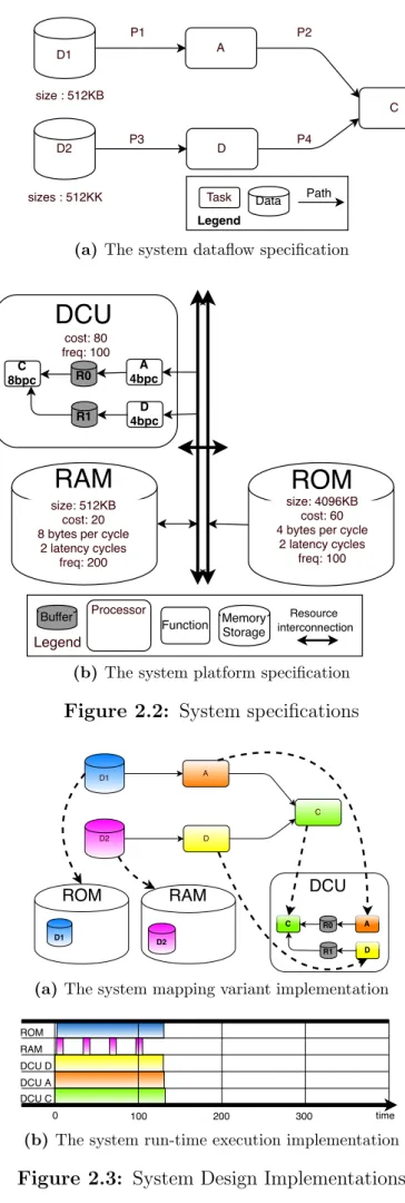
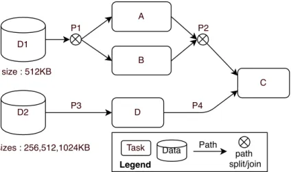
The data-flow processing application: the processing flow that fulfill the HMI’s functional requirements is captured by a data-flow oriented application support-ing concurrent behaviour. Fig. 2.3(a) illustrates a data-flow specification with functional properties (e.g., image size, task), non functional properties (e.g., im-age and task rendering quality) and quality attributes (e.g., overall quality). Images are processed by graphical tasks1. Image D1 is processed by tasks A and
image D2 is processed by task D. The image produced by A, and the image pro-duced by D, are then processed by task C, which delivers the final result onto the display.
A resource-constrained hardware platform: The hardware platform, Fig. 2.3(b), is described by a set of interconnected hardware components with functional properties (e.g., memory capacity, processor functions), non-functional proper-ties (e.g., memory and processor bandwidth, cost, frequency) and quality at-tributes (e.g., overall cost). Image processing functions A, C, D are provided by a non-programmable Display Controller Unit (DCU). Within the DCU, there is a processing pipeline composed of three functions A, D and C, which finally render the result onto the vehicle display. A processing pipeline is composed of several hardware-implemented processing functions that may differ in processing band-width (i.e., different byte per cycle performance). Directed edges denote the processing flows followed by data that transit through the processing pipeline of processors using internal FIFO-buffers, while functions may be applied or not2.
1Other data parameters than image sizes, compression or scale factors, such as transformation
matrix, masks etc. can be ignored as they do not interfere with the finding of the suitable designs.
2Bus systems, memory controllers, memory banks and cache memories can be ignored as they do
D1 D2 A C sizes : 512KK P1 P2 P3 size : 512KB D P4
Task Data Path
Legend
(a) The system dataflow specification
size: 4096KB cost: 60 4 bytes per cycle
2 latency cycles freq: 100 A 4bpc C 8bpc R0
ROM
RAM
D 4bpc R1 size: 512KB cost: 20 8 bytes per cycle2 latency cycles freq: 200 cost: 80 freq: 100
DCU
Resource interconnection Function MemoryStorageBuffer Legend
Processor
(b) The system platform specification Figure 2.2: System specifications
D1 D2 A C D A C R0 D R1 DCU ROM D1 RAM D2
(a) The system mapping variant implementation
ROM DCU D DCU A DCU C RAM 100 200 300 0 time
(b) The system run-time execution implementation Figure 2.3: System Design Implementations
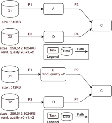
A mapping of the application on the platform: (Fig. 2.3(a)), illustrates a mapping (i.e., software implementation) of the application onto the platform. Images D1 and D2 are, respectively, stored onto ROM and RAM. The data-flow processing application, composed of tasks A, D and C, is implemented using the DCU hardware pipeline. There are various ways of mapping this application on this platform as the images D1 and D2 can be stored on RAM or ROM. This mapping variant (Fig. 2.3(a)) is one of the 4 possible mappings (so called mapping space). A run-time execution of the mapping: Fig. 2.3(b) sketches a system execution3.
Images are fetched from the memories and processed by the hardware functions at different processing bandwidths (i.e., RAM bandwidth is higher than ROM one, byte per cycle processing capabilities of C hardware function of the DCU is twice faster than A and D ones). Bandwidth and latency of the hardware components and their interactions determine the overall execution time. A system variant may have multiple executions (execution space) according to scheduling opportu-nities of the application elements (task and images) over the platform resources (processor and memories).
Variability-intensive applications
In the instrument cluster domain, multiple dataflow variants can achieve the
func-tional requirements (cf. Fig. 2.4). In our example, image D1 can be processed
by functionally-equivalent tasks A or B, while D2 has three different possible resolu-tions. The task and image resolution impacts the HMI rendering quality. In our case, performing B instead of A improves the rendering quality significantly. Also, as the resolution of D2 increases, the overall quality raises as well. Such variability is mainly due to the fact that instrument clusters are more and more developed as product lines. Fig. 2.4 specifies six alternative data-flows (application space), i.e., application variants. The highest rendering quality is achieved by the application variant that processes the image D1 by the task B while the data D2 has the highest resolution (i.e., 1024KB). On the contrary, the variant where D2 is at the lowest resolution and D1 is processed by the task A has the lowest rendering quality. The image resolution impacts the overall system quality but also the total amount of bytes of data to process, which can influence the rendering time.
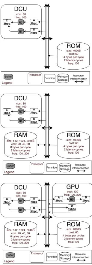
Highly-configurable platforms
At the platform level (Fig. 2.5), hardware providers generally offer adapted platform product lines for each range of infotainment services. Thus, multiple platform configu-rations (platform space) are possible at hardware manufacturing time. in our example, some configurations propose an additional RAM storage and/or a graphical processing unit GPU to increase functional capacities and processing bandwidth of the platform (e.g., GPU provides two parallel processing pipelines). The first is composed of A and B processing functions. The second is focusing on high-speed processing of task D4.
GPU and RAM are optional as some basic applications only store input images in ROM and use DCU to process and render them directly to the display. Yet, they improve the 3Memory accesses optimization such as prefetching and burst modes are not detailed as it is a
low-level system concern. Engineers can determine such details in late development stages.
4The D function of the GPU is implemented with more transistors and is thus 4 times faster than
D1 D2 A C sizes : 256,512,1024KB rend. quality:+0,+1,+2 P1 P2 P3 size : 512KB D P4
Task Data Path
Legend D1 D2 B rend. quality +2 C sizes : 256,512,1024KB rend. quality:+0,+1,+2 P1 P2 P3 size : 512KB D P4
Task Data Path
Legend
Figure 2.4: Alternative data-flow variants
platform processing and storage capacity for a higher manufacturing cost. Note that there is a presence condition between RAM and GPU as RAM acts as a dedicated cache memory for GPU. Whereas RAM can be used without GPU, e.g., to store more data or larger images. In our example, RAM comes in three alternative capacities (at different costs). On the other hand, RAM, GPU and ROM have alternative frequencies acting as a scale factor for data processing/transfer bandwidth for processors and memories witch could influence the execution time.
As a result, this configurable hardware platform is a product line of 19 electronic targets. Each electronic target is a platform configuration of heterogeneous hardware components like non-programmable processors and data storage units with a deter-mined cost, functionality, and capacity. The cheapest platform configurations, limited to 4096KB of storage, are those providing only the mandatory hardware components (ROM and DCU). Configurations with a GPU and the highest-capacity RAM are 2.42 times more expensive, but can store up to 6144KB. Also, processing task D is up to 8 times faster using GPU rather than DCU. To the same extent, the transfer bandwidth of RAM is much higher than ROM (4 times higher).
Variability-Intensive Embedded System Design Space
A system variant result from a specific mapping variant that implements a specific application variant onto a specific platform variant. This threefold variability we observed in the instrument cluster is typical of embedded systems [Pretschner et al., 2007]. The variant space grows exponentially in terms of design variations, and two different system variants thus present design variations at (one or many of) these three variability dimensions. Besides, a system variant may exhibit multiple possible executions (execution space) that can differ from scheduling of the application elements over the platform resources (e.g., tasks can be executed onto resources in different
size: 4096B cost: 60 4 bytes per cycle
2 latency cycles freq: 100 A 4bpc C 8bpc R0
ROM
D 4bpc R1 cost: 80 freq: 100DCU
Resource interconnectionFunction MemoryStorage Buffer
Legend
Processor
size: 4096B cost: 60 4 bytes per cycle
2 latency cycles freq: 100 A 4bpc C 8bpc R0
ROM
RAM
D 4bpc R1 size: 512, 1024, 2048B cost: 20, 40, 80 8 bytes per cycle2 latency cycles freq: 100, 200 cost: 80 freq: 100
DCU
Resource interconnectionFunction MemoryStorage Buffer
Legend
Processor
size: 4096B cost: 60 4 bytes per cycles
2 latency cycles freq: 100 A 4bpc C 8bpc R0 B 2bpc A 8bpc R0
ROM
RAM
D 4bpc R1 D 16bpc size: 512, 1024, 2048B cost: 20, 40, 80 8 bytes per cycle2 latency cycles freq: 100, 200 cost: 80 freq: 100 cost: 120 freq: 100, 200
DCU
GPU
Resource interconnection Function Memory Storage Buffer Legend Processororders). A system design alternative (or design for short) is composed of a system variant (design structure) with a particular system execution (design behavior).
The resulting Variability-Intensive Embedded System Design Space is the set of every possible system designs. Among these design alternatives, not all fulfill the functional requirements due to hardware limitations on the functional level. The same holds for the non-functional requirements as the cost of the platform configuration, the quality of the given data-flow application variant, or the run-time execution of the system may not reach the expectations due to limited hardware capacities.
Functional requirements
To guarantee that a design is capable of rendering the HMI without any problems, the design should first exhibit a consistent structure (a compatible triplet of application, mapping, and platform variants). “Any task and data of the data-flow variant are mapped to, respectively, processors and memories of the platform configuration.” i.e., which tasks must be processed, which tasks exchange data with others, which memory storage is accessible by processors, and how tasks (resp. data) can be mapped onto processors (resp. memory storage).
The design structure (system variant) could also be inconsistent as it exhibits a platform variant with the GPU without the RAM (violating thus the platform con-sistency) or an application variant with both tasks A and B (application consistency violated). Also, if the mapping variant exhibits the task B mapped on GPU without a platform variant with GPU, or a data mapped into a non selected RAM (violating thus mapping to platform consistency) as well as a data mapped on an unreachable memory for the processor that implements the task, i.e., processor where the task is mapped (which violates the mapping consistency).
Secondly, the design should also exhibit an error-free execution as a behavior. Graphical processors (e.g., GP U and DCU ) have limited hardware functions, and memories (e.g., RAM and ROM) have limited storage capacities. The execution of the tasks must terminate without bugs (e.g., such as deadlock) or violation of platform capabilities (i.e., misusing hardware pipelines or communication paths between compo-nents, exceeding the available memory). This termination property not only depends on the structure of the design but mostly on its behaviour, as particular scheduling of tasks and data transfers may cause deadlocks or memory overflow. Some other tradi-tional behavioral properties, such as safety or liveness checking, may also be required. Non Functional requirements
In addition to functional (FC) Requirements, the design must also meet Non-Functional (NF) requirements. In our example, these commonly include a maximal manufacturing cost, a minimal rendering quality, and responsiveness (i.e. time to render graphics on the visual display from which frame per second is determined), called NF constraints. Not all designs can meet the whole set of NF constraints. A higher-quality data-flow variant may increase the total amount of bytes the platform should store and process. A platform configuration with more memory storage and processing performances gen-erally comes at a higher manufacturing cost. Finally, the rendering time depends on the application variant workload/platform configuration capacities association but also their mapping and scheduling.
Manufacturing cost and rendering quality are quality attributes depending only on the design structure. Execution time, however, depends on both structure (e.g.,
data size, processor frequency) but emerges from the design behavior execution (i.e., scheduling of tasks, processing bandwidths, and memory access operations). However, as market competition forces engineers to deliver the best system to each specific cus-tomer. Among many designs, they must find those offering the best trade-off between the quality attributes (i.e., multi-objective optimization NF requirements).
2.1.2
Suitable Designs
Given such requirements and specifications, system engineers need to find some suit-able designs that fulfill functional requirements but also meet (and even optimize) multiple quality attributes (manufacturing cost, rendering quality, execution time, etc.). This may involve making complex design choices at both application, platform, mapping, and scheduling levels. In the instrument cluster industry, general questions engineers have to answer are:
1. Which designs can properly render the customer HMI to the vehicle display? : The first step is usually to identify designs that meet at least the customer functional requirements.
2. Which feasible designs, with an execution time less than 30.0 ms, have the cheap-est manufacturing cost : Responsiveness is important, and to make economies, part of the quality can be neglected.
3. Which feasible designs, with an execution time less than 30.0 ms, expose the highest rendering quality? : To propose an instrument cluster with high-grade quality, the focus can be on rendering quality.
4. Which feasible designs, with a rendering quality score of, at least5, 1 (low-quality
grade) and a manufacturing cost lower than 20.0$, exhibit the fastest execution time?6: The focus is on responsiveness, but minimal quality and maximal budget are also defined.
5. Which feasible designs reach the best trade-off between rendering quality, manu-facturing cost and execution time? : While no clear expectations are defined, one can arbitrary select design by trade-off on multiple quality attributes.
To answer those questions, let us consider some suitable designs on our example (see Fig. 2.6). These designs present different design choices having complex influences on their functional feasibility, non-functional satisfiability, or even their optimality w.r.t. non-functional requirements. The designs presented fulfill the functional requirements except for the design (d), which exceed memory capacity. Design (d) is not feasible in practice; trying to prototype it is a waste of time and effort.
According to its platform variant, the design (a) is one of the cheapest (i.e., de-sign choices to not select RAM nor GPU reduce the manufacturing cost drastically). Even if the ROM is the bottleneck, its execution time meets the non-functional requirements. However, due to its application variant, this design exhibits an extremely low rendering quality.
5The quality is generally informal and determined through lower or higher resolution, and more or
less advanced graphics technologies increasing the visual quality of the HMI (e.g., advanced filtering and anti-aliasing, lighting and shading, compression format
6In addition to run-time, other metrics such as processing or memory bandwidths consumption
A 4bpc C 8bpc R0 ROM D 4bpc R1 DCU D1 512 D2 256 ROM DCU D DCU A DCU C 100 200 300 400 0
(a) Cost 14.0$, Quality 0, Exec. Time 20.0ms
A 4bpc C 8bpc R0 ROM D 4bpc R1 DCU RAM freq: 200 size: 512 D2 512 D1 512 ROM DCU D DCU A DCU C RAM 100 200 300 0 400
(b) Cost 18.0$, Quality 1, Exec. Time 13.0ms
A 4bpc C 8bpc R0 ROM D 4bpc R1 DCU D1 512 D2 512 B 2bpc A 8bpc R0 D 16bpc freq: 200 GPU RAM P4 512 P2 512 freq: 200 size: 2048 ROM GPU D GPU B DCU C RAM 100 200 300 0 400
(c) Cost 34.0$, Quality 3, Exec. Time 26.0ms
A 4bpc C 8bpc R0 ROM D 4bpc R1 DCU D1 512 D2 1024 B 2bpc A 8bpc R0 D 16bpc freq: 200 GPU RAM P4 1024 P2 512 freq: 200 size: 2048 ROM GPU D GPU B DCU C RAM 100 200 300 0 400
RAM capacity exceeded Deadline missed
(d) Cost 34.0$, Quality 4, Exec. Time 35.0ms Figure 2.6: Suitable Designs
Design (b) presents a small size RAM on which D2 (medium quality selected) is stored. This allows for fetching images in parallel, removing, thus, memory bot-tleneck. In addition, this provides a faster and higher rendering quality execution at an extra cost. Interestingly, design choices that reduce D2 quality or memory frequency (i.e., from 200 to 100Mhz) do not impact the execution time (i.e.,RAM memory bandwidth is far from being a run-time bottleneck).
Design (c) exposes the highest cost, but also a high rendering quality as the engineers select a data-flow variant with B task and medium D2 quality. However, this leads to an execution time dangerously close to non-functional constraints, thus presenting a risk to system responsiveness.
According to its application variant, design (d) presents the highest rendering quality as it implements application variant with B processing and the highest D2 resolution. Unfortunately, it seems that the NF constraint on execution time will definitely be violated. Moreover, RAM maximal storage capacity is also exceeded as it needs at least 2560KB. a b c b* a+ a* 130 200 260 400 140 180 200 340 execution time 3 2 1 0 Rend. Quality manuf. cost Promising Designs for question 2 Promising Designs for question 3 Promising Designs for question 4 Legend
Figure 2.7: Pareto front with some of the optimum designs.
Fig. 2.7 shows a Pareto front [Hu et al., 2013] with some of the optimum designs. While some designs are clearly suitable solutions to engineering questions, others can be proposed as alternatives. For example, regarding question 2. Fig. 2.7 presents two risky solutions, a low quality design (a) and a close to deadline design (a+). One could advise the customer to select the design (b) to further developments as quality and run-time performance increase, respectively, up to 100% and 35% while the cost increase of 40%.
2.1.3
Discussion
The instrument cluster from which we extract the running example has been designed and implemented on a real instrument cluster by Visteon engineers. Thanks to decades in embedded system engineering, they could make - not without difficulties - suitable
design choices to finally get a prototype that meets and optimize requirements. If the platform had been still in development, the engineers would not have the possibility to prototype several designs to get a suitable solution.
Surprisingly, the size and complexity of the data-flows variants and platform con-figurations were medium to low, according to engineers. The extra difficulty may have emerged from the variability present in these specifications and their possible mapping and scheduling opportunities. This instrument cluster development was rela-tively recent (2016) and tended to corroborate that variability at both system specifica-tions and implementation levels are constantly growing [Brugali and Hochgeschwender, 2017, Passos et al., 2016] in various software and embedded system industries.
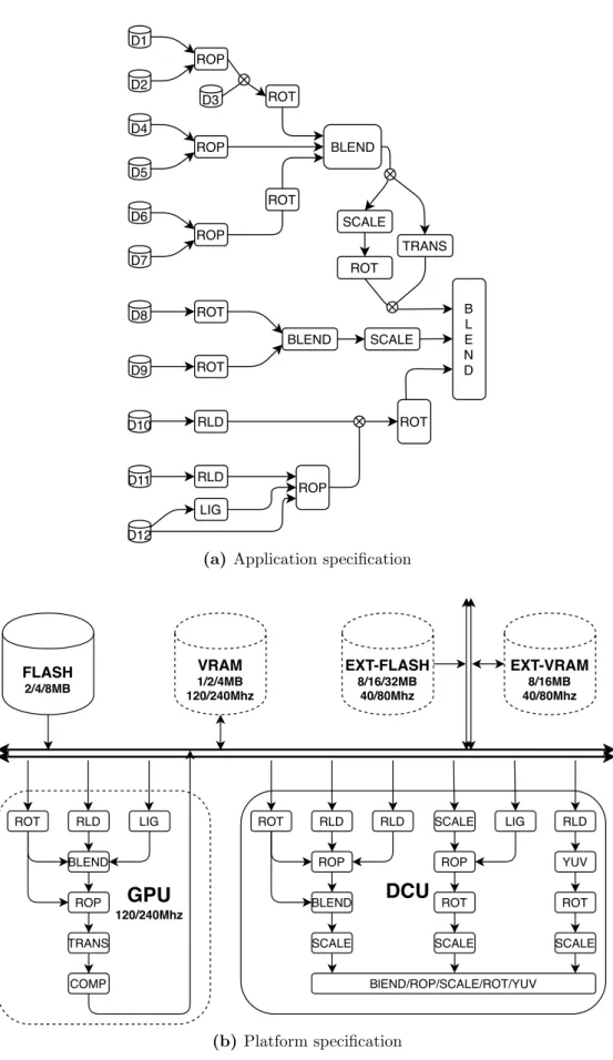
Given 6 application variants and 19 platform configurations, the running example shows up 1139 feasible system designs can be prototyped, from which 939 meet the requirements while all the executions of the designs can be encoded in a state machine with 690 000 different states. In contrast, the majority of mid-end instrument clusters (systems specifications illustrated in Fig. 2.8), the number of application variants, and platform configurations could reach several hundreds of alternatives. A state machine of at least 59 000 000 states is needed to encode all the execution traces of the 34 560 designs (see Chap. 9).
Besides the variant spaces, the complexity of a mid-end instrument cluster is also much higher. In our example, data-flow variants have (on average), 2 source images, 3 tasks, 4 data-paths, 2218KB of data to process, and platform configurations have of 5 hardware functions, and 4850KB storage capacity provide by 2 storage memories. Whereas majority of instrument clusters have data-flow variants with 13 source images, 16 tasks processing 6656KB of data through 25 paths and platform configurations have a storage capacity of 20MB provided by 4 storage memories and 24 hardware functions.
2.2
Detailed Challenges
Finding suitable designs w.r.t requirements requires not only a way to deal efficiently with a variability-induced combinatorial explosion at the three levels (i.e., application, mapping, platform), but also a way to reason simultaneously and efficiently about var-ious facets of the problem emerging from different types of concerns: feasibility/sat-isfiability and optimality; functional and non-functional requirements; and different types of aspects: behavioural and structural aspects of the system design. Concretely, this requires efficiently solving all combinations of concerns on aspects. The different facets can be classified by concern as follows:
Satisfying the functional requirements (FC), that is, checking the structure of the design (i.e., system variant); is it consistent in order to be implemented? (facet FC-S) and checking its behaviour (i.e., execution); is the HMI rendering terminate without any error? (facet FC-B).
Satisfying the non-functional requirements (NF), that is, checking those that depend only on the structure: can it be implemented within this budget? (facet NF-S) and those that also depend on the behaviour; is the design behavior renders the HMI at a minimum of 30 frames per second? (facet NF-B).
Optimizing multiple quality attributes (facet NFO). This facet requires consid-ering all quality attributes simultaneously. Optimizing the structure; which ones
are the cheapest? (facet NFO-S) and then the behaviour; which ones are the fastest? (facet NFO-B) or vice-versa may lead to sub-optimal solutions.
Reasoning on all the problem facets requires to analyze both design structure and behaviour simultaneously in order to check its functional feasibility, non-functional satisfiability, and optimality. As previously discussed, even for system experts, these activities are extremely tedious, time-consuming, and error-prone. High system vari-ability at the three introduced levels (application, platform, and mapping) but also high complexity in system executions and scheduling prevents any enumeration-based exhaustive feasibility checking, let alone exhaustive reasoning/optimization on quality attributes (e.g., cost, rendering quality, run-time). Given the complexity and vari-ability of the vast majority of instrument cluster systems, systematic consideration of all design alternatives is unfeasible for system engineers. To proactively assist system engineers in finding suitable designs faster and with more confidence, efficient methods giving the means to make appropriate design choices at early stages of development appear as a necessity.
In this thesis, we propose a model-based system design framework. Instead of man-ually finding suitable designs, we propose a model-driven framework that captures, manages, and reasons on designs through model abstractions (i.e., variable system specifications, mappings, and resulting variability-intensive design space). This ap-proach reduces system prototyping gaps and makes possible design decisions at early development stage through model abstractions and simulations. In this approach, we determine three challenges to be tackled by this framework:
1. Challenge 1: Capturing functional and non-functional high-level variable re-quirements and specifications of embedded systems that can vary at both appli-cation and platform levels. The modeling method and languages should allow engineers to model many data-flow variants and platform configurations effi-ciently and at the adapted level of details. Imposing them to manually model all data-flow variant and platform configurations could be a threat to applicability in industry.
2. Challenge 2: Deriving automatically, from the application and platform mod-els, the possible ways of mapping and scheduling application variants onto plat-form configurations (all consistent triplets of application, mapping and platplat-form variants) and their behaviors. The resulting design space model has to take into account all variations from the system specifications (i.e., application and platform) to system implementations levels (i.e., mapping and scheduling) while capturing all the structural, behavioural, functional and non-functional aspects of each design alternative efficiently.
3. Challenge 3: Evaluating simultaneously and efficiently all facets of the problem FC-S, FC-B, NF-S, NF-B, NFO; the functional feasibility, the non-functional satisfiability, and optimality at both structural and behavioural aspects of each design alternative. The evaluation method should scale to industrial systems. Knowing that the design space grows exponentially with the number of design variation points and scheduling opportunities, exhaustive and enumeration-based methods may lack of scalability.
ROP D1 D2 D8 D9 D10 D11 D12 BLEND ROP D4 D5 ROP D6 D7 ROT BLEND ROT B L E N D LIG RLD ROP ROT SCALE RLD SCALE ROT ROT ROT TRANS D3
(a) Application specification
RLD BLEND ROP TRANS COMP LIG ROT RLD ROP BLEND SCALE RLD ROT SCALE ROP ROT SCALE LIG BlEND/ROP/SCALE/ROT/YUV RLD YUV VRAM 1/2/4MB 120/240Mhz EXT-VRAM 8/16MB 40/80Mhz EXT-FLASH 8/16/32MB 40/80Mhz FLASH 2/4/8MB GPU 120/240Mhz DCU ROT SCALE (b) Platform specification
Chapter 3
State of the Art
3.1
Model Based Design of Embedded Systems
“An embedded system is an engineering artefact involving computation that is sub-ject to physical constraints” [Henzinger and Sifakis, 2007, Henzinger and Sifakis, 2006, Wymore, 2018]. These constraints emerge from limited hardware capabilities on which the embedded system is built. It is thus not possible to ignore hardware at both func-tional and non-funcfunc-tional level when designing embedded systems. Hardware abstrac-tion that is generally present in software engineering cannot be reused in embedded system development. On the contrary, hardware and software artifacts are generally mixed (i.e., hardware/software co-design [Edwards et al., 1997,De Michell and Gupta, 1997]) in order to meet the requirements that require to optimize the quality and per-formance of such systems while reducing their cost. Consequently, a holistic approach, combining requirement engineering [Macaulay, 2012], computation [Hopcroft et al., 2001] control theory [Abdelzaher et al., 2008], software [Van Vliet et al., 2008] and hardware design [Wescott, 2011] is often necessary.
Instead of directly prototyping designs, a model-based design framework captures and reasons formally on designs through model abstractions in order to generate system implementations 1 that fulfill the requirements [Edwards et al., 1997, De Michell and Gupta, 1997]. Nowadays, the complexity of system requirements and specifications leads to an immense number of system design alternatives. Such design spaces may be intractable to engineers. Strategies to support engineers to find the most suitable designs appear as a necessity.
We study model based-design of embedded systems as it proposes to identify by de-sign space exploration the most suitable system dede-signs from system specification mod-els. A plethora of model-based design frameworks exists 2 [Densmore and Passerone,
2006,Sangiovanni-Vincentelli, 2007]. Some are software-centric, aiming to find suitable software design for a particular hardware architecture. On the other hand, hardware-centric frameworks help to design for a specific application domain. Finally, system-centric frameworks focus on the suitable mapping of an application onto hardware (and software) components. Our class of problems falls into a system-centric design paradigm.
Besides, a framework is built to model a particular kind of systems from control-dominant or dataflow-control-dominant systems (e.g., train/plane controller, scheduling plan, IoT, data-flow-oriented or distributed system). Alternatively, some frameworks assess
1Process from which specifications are transformed to system is called system synthesis. 2Several hundreds.
Figure 3.1: Y-Chart Design Space Exploration Pattern
a particular type of requirements or properties (e.g., execution time, quality, energy consumption, bandwidth/throughput, temperature, reliability, security, robustness, quality assurance). The key factors of a framework are the quality of input mod-els abstractions (i.e., modelling time and expressivity) and quality of the evaluation method (i.e., analysis time and correctness3). These factors are often intertwined and
domain-dependent, which increases the variety of frameworks.
3.1.1
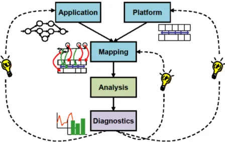
Y-Chart Pattern Overview
The Y-Chart pattern (see Fig.3.1) is a system-centric model-driven pattern. It offers a clear separation of concerns between application, platform, mapping, and analysis concerns based on models and models-transformations. This pattern consists of three stages. In the first stage, a.k.a. modelling stage, the system requirements and spec-ifications are modelled by engineers. Platform specification represents the reusable architecture of hardware and software components. On the other side, the application specification only describes, independently to any specific platform or programming language, the functional 4 logic needed to fulfil the functional requirements.
Secondly, given these system specifications and non-functional requirements, the framework will map 5 the application onto the platform in order to derive a system
design. The third stage is the analysis stage. The designs are generated into an analysis model such as analytical, computation, or simulation to evaluate the system design space. There is a profusion of methods to explore the design space [Gries, 2004, Singh et al., 2013, Singh et al., 2017] such as operational research, formal verification or simulation techniques. Random sampling, Monte-Carlo, Tabu, or best first search can optimize the design space exploration. When design space is huge, approximate exploration techniques such as genetic algorithm, simulated annealing, hill climbing can be used. At the end, even if impressing exact and approximate design space exploration techniques have been proposed, scalability is still an open issue [Gries, 2004, Singh et al., 2013, Singh et al., 2017].
3Also called implementation gap, to refer to the difference of performance between the model of
the design and its physical implementation.
4Also called business logic.