HAL Id: hal-00703607
https://hal.archives-ouvertes.fr/hal-00703607
Submitted on 4 Jun 2012
HAL is a multi-disciplinary open access
archive for the deposit and dissemination of
sci-entific research documents, whether they are
pub-lished or not. The documents may come from
teaching and research institutions in France or
abroad, or from public or private research centers.
L’archive ouverte pluridisciplinaire HAL, est
destinée au dépôt et à la diffusion de documents
scientifiques de niveau recherche, publiés ou non,
émanant des établissements d’enseignement et de
recherche français ou étrangers, des laboratoires
publics ou privés.
Towards a Generic Model for Situational Method
Engineering
Jolita Ralyte, Rebecca Deneckere, Colette Rolland
To cite this version:
Jolita Ralyte, Rebecca Deneckere, Colette Rolland. Towards a Generic Model for Situational Method
Engineering. CAISE, 2003, Velden, Austria. pp.95-110, �10.1007/3-540-45017-3_9�. �hal-00703607�
Towards a Generic Model for Situational Method
Engineering
Jolita Ralyté, Rébecca Deneckère, Colette Rolland
CUI, University of Geneva, Bd. Du Général Dufour, 24, CH1211 Geneva, Switzerland CRI, University of Paris Sorbonne, 90 rue de Tolbiac, 75013 Paris, France
[email protected], {denecker, rolland}@univ-paris1.fr
Abstract. The work presented in this paper is related to the area of Situational Method Engineering (SME), which focuses on project-specific method construction. We propose a generic process model supporting the integration of different existing SME approaches. This model shall help the method engineer either selecting one SME approach or combining several approaches that best fit the situation of the method engineering project at hand. The generic model presented in this paper already contains three SME techniques: (1) to assemble method chunks (2) to extend an existing method and (3) to generate a method by abstraction/instantiation of a model/meta-model. The paper presents and illustrates these three techniques and show how other SME techniques could be integrated in the model.
1. Introduction
The need for a better productivity of system engineering teams, as well as a better quality of products motivates the development of solutions to adapt methods to the project situation at hand. This is known as Situational Method Engineering (SME). Whereas SME promotes the construction of a method by assembling reusable method fragments stored in some method base [9, 3, 18, 19, 23, 29, 26], in this paper we propose a generic process model to capture a large variety of approaches supporting “on the fly” method construction.
As the selection of the suitable method engineering approach for the project at hand is not easy, our generic process model guides the method engineer in the definition of his/her project method engineering goal and in the selection of the approach which best allow him/her to achieve it. Besides, as in some cases a combination of several approaches could be the most suitable engineering solution in order to construct or adapt a method, the generic process model guides the method engineer in selecting the appropriated set of approaches.
We use a strategic process meta-model called Map to represent our generic SME process model. Map provides a representation system based on a non-deterministic ordering of intentions and strategies. A map is a labeled directed graph with intentions as nodes and strategies as edges between intentions. A triplet <source
intention, target intention, strategy> in the map is called a section. Each section is defined by an intention achievement guideline, which provides advice to fulfil the
target intention following the strategy given the source intention has been achieved. The directed nature of the graph shows which intentions can follow which one. An edge enters a node if its strategy can be used to achieve the intention of the node. Since, there can be multiple edges entering a node, the map is capable of representing the many strategies that can be used for achieving an intention. Thus, Map allows us to integrate different approaches as different method engineering strategies in the same SME process model and to combine the application of these approaches in the construction of a new method or the adaptation of a given one.
In previous papers we presented a process model for assembly based situational method engineering [19], an approach for method extension based on the use of patterns [5, 6] and more recently, an abstraction based approach [24] responding to the needs of a large method engineering project in industry. All these approaches use different techniques for method construction but their objective is the same – to support the construction of a method matching the requirements of a given, specific situation.
Our belief is that it will be useful to investigate the problem of integrating different approaches in a single SME process model. This is the objective we aim at in this paper. We propose a generic SME process model, which integrates the three above-mentioned approaches. We also show that this model is flexible enough to integrate other approaches than the three that are integrated and illustrated in this paper.
The paper is organised as follows: section 2 describes our generic process model for situational method engineering. Sections 3, 4 and 5 present and illustrate respectively three method engineering approaches, named Assembly-based,
Extension-based and Paradigm-based, all being integrated in our generic model. Section 6 considers the similarities and the differences of these approaches and the possibility of their parallel us in the construction of a single method whereas section 7 draws some conclusions and discuss about our future work.
2. Generic Process Model for Situational Method Engineering
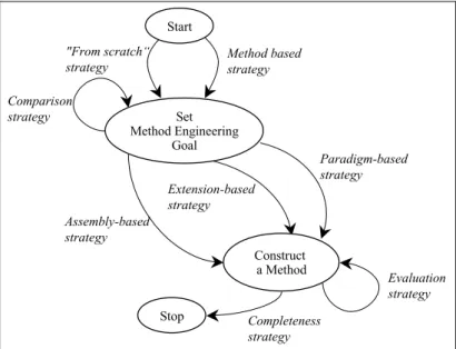
We consider that any SME process is made of two main tasks: setting the method engineering goal and then, constructing a method that matches this goal. In other words, there are two core intentions that the method engineer has in mind:1. Set Method Engineering Goal that is to identify the kind of method he/she needs, 2. Construct a Method allowing him/her to satisfy this goal.
These intentions are the nodes of the map presented in Fig.1. As shown in this figure, the Map representation formalism allows us to propose several different strategies to support the realisation of these intentions.
The achievement of the first intention, namely Set Method Engineering Goal depends of the method situation of the project at hand. In some project situation the method engineer may perhaps consider that a specific method could be applicable but requires some adaptations whereas in other situations, he or she may be convinced that any of the available methods is suitable for the project. In the first case, the method engineering (ME) goal of the method engineer refers to the adjustments of the selected method: enhancement, extension or restriction. We call the corresponding
strategy the Method driven strategy. In the second case, he or she decides to construct a completely new method and the corresponding strategy is called the From scratch
strategy.
The achievement of the intention Construct a Method depends of the applied method construction technique. Thanks to the map structure it is easy to integrate in the same model different method construction techniques as different strategies to reach the intention Construct a method. The map of Fig. 1 proposes three SME techniques. The first one is based on the reuse of method components extracted from existing methods and stored in some method base. This technique helps to select and assemble different method components in order to construct a new method or to enrich an existing one. As a consequence, the corresponding strategy in our SME process model is called Assembly-based strategy. The second technique is used for extending a method by applying extension patterns and therefore it is referred to in the map by the Extension-based strategy. Finally, the third technique is relevant when a new fresh method must be constructed either by abstracting from a given model or by instantiating a meta-model. This new method develops its own paradigm and this is why the corresponding strategy is called the Paradigm-based strategy. It is obvious that these three strategies can be combined in order to construct the method best fitting the situation of the project at hand.
Once the required method has been constructed it is necessary to validate it. For this, we propose the Evaluation strategy, which implements different method evaluation techniques. Our Generic Process Model for SME is shown in Fig. 1.
Stop "From scratch“ strategy Method based strategy Extension-based strategy Assembly-based strategy Comparison strategy Paradigm-based strategy Start Evaluation strategy Set Method Engineering Goal Completeness strategy Construct a Method
Fig. 1. Generic Process Model for Situational Method Engineering
It is obvious, that other SME techniques could be integrated in our generic SME process model as other strategies to achieve the intention Construct a method. In this
paper we concentrate on the three method construction techniques introduced in the map above and we present and illustrate them in the following sections.
3. Assembly-Based Method Engineering
Our approach for assembly-based SME aims at constructing a method ‘on the fly’ in order to match as well as possible the situation of the project at hand. It consists in the selection of method components (that we call method chunks) from existing methods that satisfy some situational requirements and their assembly.
Our approach is requirements-driven, meaning that the method engineer must start by eliciting requirements for the method. Next, the method chunks matching these requirements can be retrieved from the method base. And finally, the selected chunks are assembled in order to compose a new method or to complete an existing one.
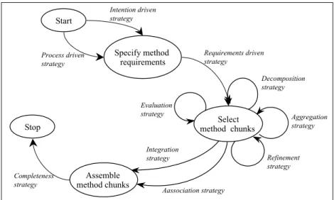
As a consequence, the three key intentions in the assembly-based method engineering process are: Specify method requirements, Select method chunks and
Assemble method chunks. Several strategies are provided in this process model in order to achieve these intentions. Fig. 2 depicts our assembly-based process model for situational method engineering.
Specify method requirements Start Process driven strategy Intention driven strategy Stop Assemble method chunks Requirements driven strategy Integration strategy Completeness strategy Aggregation strategy Decomposition strategy Aassociation strategy Refinement strategy Evaluation strategy Select method chunks
Fig. 2. Assembly-Based Process Model for Situational Method Engineering
3.1 Method requirements specification
The elicitation of method requirements must be done in the light of the method engineering goal set previously (see Fig.1) that might be to adapt an existing method
or to construct a new one. We identified two different strategies for requirements elicitation, namely Intention driven strategy and Process driven strategy (Fig. 2).
The first strategy is suitable for method adaptation. There are different types of method adaptation. The method in use can be strong in terms of its product model but weak with respect to its process model, which will be the subject of adaptation and enhancement. The adaptation can be to simply add a new functionality to the existing method, which is relevant in its other aspects. Vice versa, the project at hand could not need some functionality offered by the method. In all these cases, the requirements elicitation process is driven by the identification of the ME intentions such as ‘add event concept’, ‘complete completeness checking step’ etc., which will allow to complete, enhance or limit the method initially selected. For this reason, wee call this strategy Intention driven strategy (Fig. 2).
The second strategy is relevant in the case of a new method construction. In such ME situation the requirements is not only to produce the list of ME intentions that will permit to adapt the selected method but to identify the full set of engineering intentions that shall be fulfilled by the new method. For this reason we call the corresponding strategy Process driven strategy.
Both of these strategies lead to a set of requirements expressed as a map that we call the requirements map. More information about the guidelines supporting these two strategies to Specify method requirements can be found in [21].
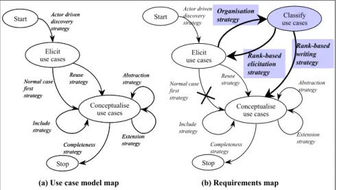
(b) Requirements map (a) Use case model map
Stop Completeness strategy Include strategy Start Normal case first strategy Actor driven discovery strategy Extension strategy Reuse strategy Abstraction strategy Elicit use cases Conceptualise use cases Stop Completeness strategy Include strategy Start Normal case first strategy Actor driven discovery strategy Extension strategy Reuse strategy Abstraction strategy Elicit use cases Conceptualise use cases Rank-based elicitation strategy Rank-based writing strategy Organisation strategy Stop Completeness strategy Include strategy Start Normal case first strategy Actor driven discovery strategy Extension strategy Reuse strategy Abstraction strategy Elicit use cases Conceptualise use cases Classify use cases
Fig. 3. Requirements Map for the Use Case Model Enhancement
As an example, let’s assume that the goal of the method engineer is to enhance the use case approach proposed by Jacobson in [11] by some scenario classification & authoring guidelines in order to improve the quality of use case conceptualisation. This is a case of method adaptation and therefore, the Intention driven strategy is the more appropriated one. This strategy supports the identification of adaptation requirements expressed as intentions and strategies as shown in Fig. 3. The initial map
for use case construction is shown in Fig. 3 (a) whereas Fig. 3 (b) highlights the requirements for enhancement expressed through three new sections (in colour) and the deletion of the section <Elicit use case, Conceptualise use case, Normal case first
strategy> which is replaced by the added features.
3.2 Method chunks selection
Once the method requirements have been specified, the selection of the method chunks matching these requirements can start. The Requirements driven strategy helps the method engineer to select the best fitting chunks. The chunk selection queries must be formulated by giving values to the attributes of the descriptors and interfaces of method chunks (see [15, 23]). The validation of the retrieved chunks is supported by the Evaluation strategy, which helps in evaluating the degree of matching of the candidate chunk to the requirements. This is done by applying similarity measures between the requirements map and the process model of the selected chunk. More details about these similarity measures could be found in [19].
The Decomposition, Aggregation and Refinement strategies help to refine the candidate chunk selection by analysing more in depth if the chunk matches the requirements. If the selected method chunk is an aggregate one, i.e. it is composed of several chunks, the Decomposition strategy drives the selection of the sub-chunks, which are relevant and eliminate the ones, which are inadequate. Vice-versa, the
Aggregation strategy is applicable when the retrieved chink matches partly the requirements. This strategy proposes to look for an aggregate chunk containing the candidate one based on the assumption that the aggregate chunk might provide a solution for the missing requirements. The Refinement strategy proposes to search for another chunk satisfying the same intention but providing different guidelines to achieve it. In our example, the query for the method chunk selection will include parameters as follows:
Application domain = ‘Information System’ AND Design activity = ‘Requirements specification’ AND Situation = ‘Use cases’ AND Intention = ‘Classify use cases’
3.3 Method chunks assembly
When at least two chunks have been selected, the method engineer can progress in the assembly of these chunks following one of the two proposed strategies in the map, namely the Association strategy and the Integration strategy (Fig. 2).
The Association strategy is relevant when the method chunks to assemble correspond to two different system engineering functionalities, i.e. they allow to achieve different engineering intentions and the result of one chunk is used as a source product by the second one. Such method chunks generally do not have common elements in their product and process models and the assembly process is therefore mainly dealing with making the bridge between the two chunks. More precisely, the product models of the chunks must be connected by defining links between their different concepts whereas the connection of their process models
consists in defining their execution order. The connection of the product model is possible thanks to the ADD_LINK and ADD_CONCEPT operators [22]. The MERGE_INTENTION operator is applied to connect the process models and consist in identifying in the first chunk the intention producing the source product for the second chunk. Some method chunk adaptation could be required before their assembly in order to avoid concepts name ambiguity. This may be done by applying different RENAME operators. For example, the chunk producing use cases and the chunk constructing the system object structure can be assembled to get a method with a larger coverage than any of the two initial ones.
The Integration strategy is relevant to assemble chunks that have similar engineering goals but provide different ways to satisfy it. In such a case, the process and product models are overlapping, that is containing the same or similar elements. The assembly process consists in identifying the common elements in the chunks product and process models and merging them. Therefore, the integration process is mainly based on the application of different MERGE operators: For example, MERGE_INTENTION and MERGE-STRATEGY for the integration of process models, MERGE_CONCEPT and MERGE_LINK for the integration of product models. Each of these operators deals with the integration of similar elements belonging to the initial chunks into a new one in the integrated chunk. The SPECIALISE and GENERALISE operators define respectively the specialisation and generalisation links between the concepts of the chunks product models. Their application is useful to build a model of the integrated method chunk which is richer than those of the initial chunks.
Like in the previous case, the method chunks adaptation task must precede their integration. The RENAME operators are used to modify the names of intentions, strategies, concepts, properties and links. Other operators such as OBJECTIFY_LINK and OBJECTIFY_PROPERTY may be required for performing more complex transformation tasks.
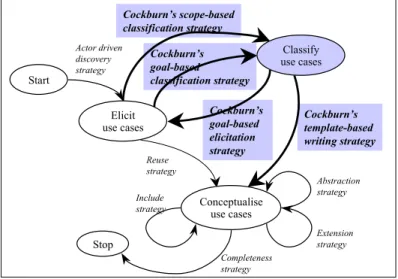
For example, the Integration strategy will be necessary to satisfy the method requirements defined in Fig. 3 as the method engineering objective is to enhance the use case conceptualisation process by new way of working. Let’s suppose that the method engineer selects the use case conceptualisation guidelines proposed by Cockburn [4]. This approach proposes two complementary use case classification techniques: one is based on a three level goal hierarchy; other defines a design scope to capture in a use case typology. These two techniques cover the section <Elicit use
cases, Classify use cases, Organisation strategy> in the requirements map. The guidelines supporting elicitation of other use cases of the lower or higher abstraction level are also provided by this approach and cover the section <Classify use cases,
Elicit use cases, Rank-based elicitation strategy> in the requirements map. Moreover, this approach proposes different templates for use case writing as well as the content guidelines depending on the use case goal level and design scope. It covers the section
<Classify use cases, Conceptualise use cases, Rank-based writing strategy>. The obtained method (Fig. 4) will provide guidelines richer than those of each chunk used separately.
Cockburn’s scope-based classification strategy Cockburn’s template-based writing strategy Cockburn’s goal-based classification strategy Cockburn’s goal-based elicitation strategy Stop Completeness strategy Include strategy Start Actor driven discovery strategy Extension strategy Reuse strategy Abstraction strategy Elicit use cases Classify use cases Conceptualise use cases
Fig. 4. The enhanced use case model map.
4. Extension-Based Method Engineering
This approach for extension-based SME [5, 6] corresponds to a method engineering goal that is to adapt locally a method to the contingency of the project at hand. The approach guides the method engineer by providing extension patterns that help identifying typical situations of extension and provide advises to perform the extension required in these situations.
Stop Select a meta-pattern Domain driven strategy Completeness strategy Pattern based strategy
Start Pattern matching
strategy
Extend a method
Fig. 5. Extension-Based Process Model for Situational Method Engineering
The map, which models the process underlying this approach, is presented in Fig. 5. It can be seen that we advocate two different ways to extend a method: (a) directly through the Pattern matching strategy or (b) using some generic knowledge related to
the domain for which the extension is to be done through the path Select a
meta-pattern, Extend a method with the pattern based strategy. The former helps to match extension patterns stored in a library to the extension requirements whereas the latter selects first, a meta-pattern corresponding to the extension domain and then, guides the method extension by applying the patterns suggested by the meta-pattern.
Both ways-of-working use a library of extension patterns but do it in different ways. The domain centric way exploits the fact that a set of patterns and their use can be embodied in a meta-pattern that is suitable for method extension in this domain (e.g. temporal data structures). If the required extension does not clearly correspond to a certain type of extension, a well-identified extension domain, then the pattern matching approach shall be selected by the method engineer.
4.1 Domain driven adaptation
This path in the process of Fig. 5 comprises to Select a meta-pattern with the
domain driven strategy and then, to Extend a method with the pattern matching
strategy. The guideline to Select a meta-pattern helps the method engineer in recognising if the extension he/she has in mind corresponds to one of the so-called extension domains. One typical example of such domain is temporal data structures. The adaptation of any method implied by this domain includes extensions such as the integration in the product model of the method of a time model with the appropriated calendar(s) (Gregorian, week-based, working-day-based etc.), the integration of temporal events and of temporal expressions for defining event occurrence conditions etc. These extensions are captured in patterns and organised in a meta-pattern. Meta-patterns for the different domains for which knowledge about the extension and how to perform it has been defined, are stored in a repository together with the corresponding patterns.
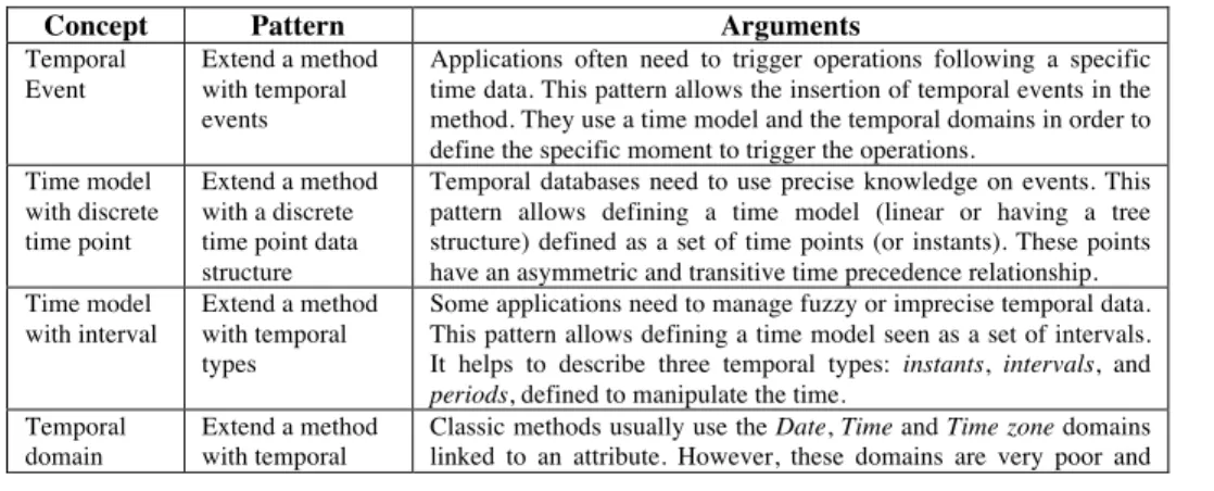
Once the method engineer has selected the meta-pattern relevant for the extension domain at hand, the pattern-based strategy guides him/her in the systematic application of the patterns associated to the pattern. Table 1 shows the meta-pattern, which guides temporal method extension.
Table 1. Meta-pattern “Extend a method with temporal concepts”
Concept Pattern Arguments
Temporal Event
Extend a method with temporal events
Applications often need to trigger operations following a specific time data. This pattern allows the insertion of temporal events in the method. They use a time model and the temporal domains in order to define the specific moment to trigger the operations.
Time model with discrete time point
Extend a method with a discrete time point data structure
Temporal databases need to use precise knowledge on events. This pattern allows defining a time model (linear or having a tree structure) defined as a set of time points (or instants). These points have an asymmetric and transitive time precedence relationship. Time model
with interval
Extend a method with temporal types
Some applications need to manage fuzzy or imprecise temporal data. This pattern allows defining a time model seen as a set of intervals. It helps to describe three temporal types: instants, intervals, and
periods, defined to manipulate the time. Temporal
domain
Extend a method with temporal
Classic methods usually use the Date, Time and Time zone domains linked to an attribute. However, these domains are very poor and
domains don’t allow the representation of relative or periodic attribute. This pattern aims at supporting the generation of these temporal domains. The time used may be valid, transaction or user-defined [30]. Object
history
Extend a method with temporal classes for object histories
Histories are sometimes needed by applications in order to look at the data evolution and to execute the replay functions required for tracking decisional process of an organization. Therefore, the application should provide information for each object state when it is/was true as well as when it is/was exploitable. This pattern permits to integrate the time management into the class definition and group properties that evolve at the same time and that are linked to the same temporal dimension.
Object versioning
Extend a method with temporal classes for object versioning
Rollback operations are more and more required in order to come back to previous states of the database. This pattern permits the creation of object histories supporting the application of rollback operations without endangering the database coherency. Documentation operations help the engineer to keep track of the different versions. Time constraint Extend a method with time constraint
The necessity to handle time introduces another problem that is to constrain data evolution. Models must include concepts helping the engineer to define which constraints are related to the time in order to keep the data coherency. This pattern uses a classification of constraints into intra-object and inter-object constraints [7] and the distinction between intra-time and inter-time constraints [2] in order to help the engineer to constrain the data evolution.
4.2 Pattern-matching based extension
The pattern matching approach to Extend a method (Fig. 5) guides the method engineer in the selection of the extension patterns, which better match his/her requirements. Therefore, the process map, which models this approach, is centred around two core intentions: Specify extension requirements and Select & Apply a
pattern. This is shown in Fig. 6 as well as the strategies to attain these process intentions. Stop Specify extension requirement Select and Apply a pattern Product extension strategy Completeness strategy Requirements elicitation strategy Start Requirements elicitation strategy Process extension strategy
The Requirement elicitation strategy helps the method engineer to construct a map representing the method extension requirements. This map is called requirements map. Introduce time model could be such an intention (the requirement), interval
based could be a strategy attached to this intention in the requirements map. Discrete
time point could be another strategy associated to the same intention. Two different requirements maps can included the same intention, Introduce time model but with different strategies. However, the same requirements map might include both, meaning that the method extension shall handle both point based and interval temporal reasoning.
In the repository extension patterns are grouped into product extension patterns and process extension patterns. The former indicate how to extend a product model whereas the latter describes a process model extension. This is reflected in the map of Fig. 6 by the two strategies to Select & Apply pattern, namely the: Product extension
strategy and Process extension strategy. Both strategies are supported by guidelines which actually try to match the requirements map intentions and strategies with the situation of the pattern. Some of the similarities introduced in section 3 are applicable here to help in finding the ‘best’ fit between the requirements and the pattern situation.
5. Paradigm-Based Method Engineering
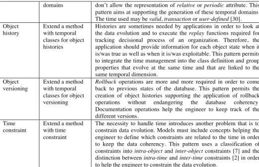
This approach uses meta-modelling as its underlying method engineering technique. It is the most generic of the three approaches to Construct a Method that we propose in our generic model for situational method engineering shown in Fig. 1. The hypothesis of this approach is that the new method is obtained either by abstracting from an existing model or by instantiating a meta-model. Our generic model offers different meta-models (i.e. different paradigms) and supports the instantiation of the one best fitting the requirements of the method engineer.
Meta-modelling is known as a technique to capture knowledge about methods. It is a basis for understanding, comparing, evaluating and engineering methods. One of the results obtained by the meta-modelling community is the definition of any method as composed of a product model and a process model [16]. The product model defines the set of concepts, their properties and relationships that are needed to express the outcome of the process. The process model comprises the set of goals, activities and guidelines to support process goal achievement and action execution. Therefore, method construction following the meta-modelling technique is centred on the definition of these two models. This is reflected in the map, which refines the
Paradigm-based strategy of Fig.1 by the two core intentions Construct a product
model and Construct a process model (see Figure 6.).
A number of product meta-models [8, 10, 17, 28] as well as process meta-models [12, 25, 27] are available and our approach is based on some of them. Fig. 7 shows our paradigm-based process model and highlights a number of different strategies to achieve each of the two core intentions. Every section in the map is supported by a guideline, which helps to achieve the target intention in the process.
Stop Construct a product model Construct a process model Abstraction strategy Instantiation strategy Strategic strategy Tactical strategy Simple strategy Refinement strategy Completeness strategy Pattern-based strategy Start Utilization strategy Adaptation strategy
Fig. 7. Paradigm-based process model for situational method engineering
The construction of the product model depends of the method engineering (ME) goal. For example, the ME goal could be to construct a method:
• by raising (or lowering) the level of abstraction of a given model, • by instantiating a selected meta-model,
• by adapting a meta-model to some specific circumstances, • by adapting a model.
Each of these cases defines a strategy to Construct a product model, namely the
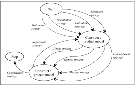
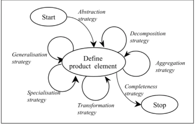
Abstraction, Instantiation, Adaptation and Utilisation strategies. Each of them is supported by a guideline. For example, the map of Fig. 8 expresses the guideline supporting the product model construction following the Abstraction strategy. According to this guideline, the product model construction consists in defining different product model elements such as objects, links and properties. It starts by the abstraction of some elements from the paradigm model. After that, the model under construction is refined thanks to the Generalisation, Specialisation, Aggregation,
Decomposition and Transformation strategies, which help to apply the corresponding product model construction operators.
The process model definition must conform to the product model. This is the reason why in the map of Fig. 7 the intention Construct a process model follows the one to Construct a product model. We know that a process model can take multiple different forms. It could be a simple informal guideline, a set of ordered actions or activities to carry out, a set of process patterns to be followed or a multi-process guideline combining several different alternative ways of working. These four cases are represented in our paradigm-based process model by four strategies: Simple,
Tactical, Pattern-based and Strategic. Simple and Tactical process models are based on the NATURE process modelling formalism [12, 25] whereas the Strategic process model, also called Map formalism, was proposed by [27] (see the introduction of this
paper). The guidelines supporting the application of these strategies can be found in [1, 20]. Aggregation strategy Decomposition strategy Transformation strategy Generalisation strategy Define product element Start Abstraction strategy
Specialisation strategy
Stop
Completeness strategy
Fig. 8. Abstraction Strategy for Product Model Construction
Fig. 9 is an illustration of the use of the Abstraction strategy to Construct a product
model in the Lyee1 industrial project. The guideline of Fig. 7 was followed for the
definition of the Lyee User Requirements Model (LURM) by abstracting from the
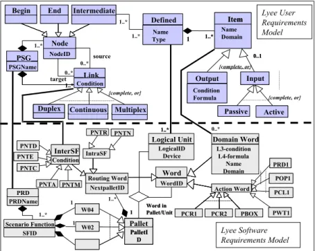
Lyee Software Requirements Model (LSRM) [24]. The latter is used by the LyeeAll CASE tool [13, 14] in order to generate programs, provided a set of well-formatted software requirements are given. These requirements are expressed in rather low-level terms such as screen layouts and database accesses. Moreover they are influenced by the LyeeALL internals such as the Lyee identification policy of program variables, the generated program structure and the Lyee program execution control mechanism. Experience with LyeeAll has shown the need to acquire software requirements from relatively high level user-centric requirements. The meta-model of the LSRM presented in the bottom part of Fig. 9 has been used as a baseline paradigm model for the more abstract LURM construction shown in the top part of Fig. 9. It is obvious that the Abstraction strategy was in this case, the more appropriated strategy to
Construct a product model.
The central concept in the LSRM is called a Word. A Word corresponds to a program variable: input words represent values captured from the external world whereas output words are produced by the system by applying specific formulae. The execution of formulae is controlled by the Process Route Diagram (PRD). A PRD is composed of Scenario Functions (SF), composed of Pallets, which are made of
Vectors. In order to carry out the generated program control the function generates its own Words, such as the Action words related to Vectors and Routing words to distribute the control over the various SFs of a PRD.
1 Lyee, which stands for GovernmentaL MethodologY for SoftwarE ProvidencE, is a
methodology for software development used for the implementation of business software applications. Lyee was invented by Fumio Negoro.
In order to comply with the Lyee paradigm, the LURM should be centred on a notion, which abstracts from the concept of Word. Obviously Words required by the Lyee processing mechanism are not relevant at this level. On the contrary, the concern is only with Domain words. Besides, there is a need to provide the requirements holder with a means to grasp a ‘set of words’ conceptually associated with one another. The notion of ‘system interaction’ is proposed for that purpose. An interaction delineates a number of input and output data, logically assembled together. Each word of an interaction is defined as a model element called Item by applying the
Abstraction strategy (Fig. 8). The concept of Defined is proposed as an aggregation of logically related Items thanks to the Aggregation strategy (Fig. 8). The Specialisation
strategy is applied in order to specialise the Item into Output and Input. An Output is produced by the system whereas the Input is captured from the user. In the same manner, the Input is specialised into Active and Passive. The former triggers the system actions whereas the latter represents values captured from the user. Similarly, the concept of PSG, the Precedence Succedence Graph was obtained by abstraction of the PRD concept from the LSRM. It specifies the ordering conditions between
Defineds as the PRD do it with Words.
1 1..* {complete, or} source target PSG PSGName PSG PSGName 0..* 0..* 1..* 1..* 1..* 1..* 1..* 0..* 0..1 Action Word W04 W02 PNTE PNTE LogicalID Device Logical Unit SFID 1 1 1 NextpalletID Routing Word NextpalletID
Routing Word Word WordID Domain Word L3-condition L4-formula Name Domain PRD1 PRD1 POP1 POP1 PCL1 PCL1 PCR1 PCR2 PBOX PWT1PWT1 Word in Pallet/Unit Word in Pallet/Unit 1..* PNTA PNTM IntraSF PNTN PNTN PNTC PNTC PRD PRDName PRD PRDName {complete, or} Name Type Defined Name Type Defined Scenario Function Lyee Software Requirements Model 1 1..* Link Condition Condition Link Condition Condition Duplex
DuplexDuplexDuplex
Duplex ContinuousContinuous MultiplexMultiplex
{complete, or} 1..* 1..* 0..1 Action Word W04 W02 PNTR 1 1..* PCR1 PCR2 PBOX Pallet PalletI D Pallet PalletI D Pallet PalletI D Pallet PalletI D Pallet PalletI D Name Domain Item Item Name Domain Item
Item Lyee User Requirements Model Begin
Begin EndEnd IntermediateIntermediate
Condition Formula
Output
Condition Formula
Output InputInput Node NodeID Node NodeID InterSF Condition InterSF Condition PNTD PNTD Passive
Passive ActiveActive
Fig. 9. Lyee Product Models for Software Requirements and for User Requirements The process part of the LURM was defined by following the Pattern-based
strategy (Fig. 7). A set of patterns have been defined to take into account different situations in the user requirements definition. Each pattern provides an advice to
capture and formulate requirements. More about these patterns, their definition and application could be found in [24].
6. Generic Features
The paper demonstrates that meta-modelling remains the core technique in SME. All approaches presented above are based on meta-modelling. In the assembly-based SME approach every method chunks must be instance of a specific meta-model for modular methods [20]. The extension-based approach depends of the model of the method to extend, which is itself instance of a specific meta-model and proposes patterns to extend this model. The patterns are generated from the meta-patterns, which are also defined at the meta level. The paradigm-based approach is typically based on meta-modelling.
All these approaches deal with the definition, instantiation, transformation or assembly of method models and meta-models. The corresponding method construction activities can be generalised by the means of a set of generic operators. As all these approaches explicitly separate the notions of product model and process model, we classify these operators in operators for process model construction and
operators for product model construction. The former generalise the actions to be performed on the product models and deal with elements such as concepts, links and properties. The later generalise the actions to be performed on the process models and deal with elements such as intentions and strategies.
An other classification of these operators relates to the type of action they perform. Such a classification is as follows:
• Unification operators are used in order to unify the terminology of the product and the process models before their integration, extension or adaptation. They generally allow to rename different elements in the process and product models. Some examples of such operators are RENAME_CONCEPT, RENAME_LINK, RENAME_INTENTION, etc.
• Transformation operators deal with the conversion of one type of product model element into another type. For example, the OBJECTIFY_LINK operator permits to transform a link between two classes of objects into a new object.
• Abstraction/instantiation operators deal with the different abstraction levels of the models. They can be used for the product model instantiation from a meta-model or its abstraction from another one.
• Specialisation/generalisation operators can be used for a connection of two product models having some concepts with similar semantics but different structures. A new concept can be generalised in order to preserve the two initial concepts in the integrated model.
• Aggregation/decomposition operators operate with different granularity levels and allow to combine or to split different product and process model elements. AGGREGATE_CONCEPTS, DECOMPOSE_CONCEPT or DECOMPOSE_ SECTION are examples of these.
• Addition operators can help to add supplementary elements in the product and process models. This might be required to connect models or to complete a model in order to fulfil some method engineering requirements.
• Cancellation operators such as REMOVE_LINK or REMOVE _STRATEGY eliminate the inadequate elements in the product model or the process.
We are aware of the fact that this list of operators is not an exhaustive one and we are currently working on it.
The last point that we propose to raise in this section concerns the requirements
matching problem. The specificity of SME approaches is that they are requirements-driven. Any method construction technique proposed by such an approach must take into account the definition of the method requirements and the selection of the solutions that satisfy them. As a consequence, the matching mechanism between the requirements model and the solution model is paramount. Our belief is that such a mechanism must include similarity measures. The method engineer needs to be able to measure the similarity of different elements from the process models like intentions, sections or entire maps as well as the similarity of different product models elements like concepts or links.
Currently every approach integrated in our generic process model proposes its own manner to resolve the requirements matching problem. Our objective is to propose some generic process and product similarity measures, witch could be adapted or instantiated in different SME approaches.
7. Conclusion
In this paper we proposed a generic process model for SME. This process model allows us to capture different approaches for project specific method construction and to provide guidelines to assist the method engineer in the selection of the approach best fitting the project situation.
Our generic process model already contains three SME approaches that can be applied separately or combined in order to construct a new method or to adapt an existing one. As this model is defined as a map with associated guidelines it is possible to include other SME approaches in a rather simple manner. They can be integrated as different strategies to satisfy the intention Construct a method (Fig. 1).
In order to provide a strong methodological support with our generic SME process model we propose a set of generic method construction operators. We are also working on different similarity measures which are necessary to evaluate the similarity between different method elements as well as for evaluating the matching conditions of a given method chunk with the method requirements.
Our future preoccupation is to complete this generic SME process model by integrating other approaches and to validate it through real projects. We will also continue refining the definition of the generic method construction operators and the metrics for process and product models similarity measurement. In some cases distance measures might be more appropriated than the similarity ones. We will also consider this solution.
References
1. Benjamen A., Une Approche Multi-démarches pour la modélisation des démarches
méthodologiques. PhD dissertation. University of Paris 1 - Sorbonne, 1999.
2. Böhlen M.H. Valid time integrity constraint. Report TR 94-30. 1994.
3. Brinkkemper S., M. Saeki, F. Harmsen, Assembly Techniques for Method Engineering. Proc. of CAiSE’98. Pisa Italy, 1998.
4. Cockburn A., Writing Effective Use Cases. Addison-Wesley, 2001.
5. Deneckere, R., Approche d’extension de méthodes fondée sur l’utilisation de composants génériques, PhD thesis, University of Paris 1-Sorbonne, 2001.
6. Deneckere, R., Souveyet, C., Patterns for extending an OO model with temporal features. Proceedings of OOIS’98 conference. Springer-Verlag, Paris (France), 1998.
7. Gehani N., Jagadish H.V. Ode as an active database: constraints and triggers. Proceedings of the 17th
VLDB, Barcelona, Spain, pp. 327-336. 1991.
8. Grundy, J.C., J.R. Venable, Towards an integrated environment for method engineering, Proc. IFIP WG 8.1 Conf. on ‘Method Engineering’, Chapman and Hall, pp 45-62, 1996. 9. Harmsen A.F., Situational Method Engineering. Moret Ernst & Young , 1997.
10. Hofstede, A.H.M. Ter., Information modelling in data intensive domains, Dissertation, University of Nijimegen, The Netherlands 1993.
11. Jacobson I., M. Christenson, P. Jonsson, G. Oevergaard, Object Oriented Software
Engineering: a Use Case Driven Approach. Addison-Wesley, 1992.
12. Jarke M., C. Rolland, A. Sutcliffe, R. Domges, The NATURE requirements Engineering. Shaker Verlag, Aachen 1999.
13. Negoro, F. Methodology to Determine Software in a Deterministic Manner. Proceedings of ICH, Beijing, China, 2001.
14. Negoro, F. A proposal for Requirement Engineering, Proceedings of ADBIS, Vilnius, Lithuania, 2001.
15. Plihon V., J. Ralyté, A. Benjamen, N.A.M. Maiden, A. Sutcliffe, E. Dubois, P. Heymans, A
Reuse-Oriented Approach for the Construction of Scenario Based Methods. Proc. of the Int.
Software Process Association's 5th Int. Conf. on Software Process (ICSP'98), Chicago, Illinois, US, 1998.
16. Prakash, N., On Method Statics and Dynamics. Information Systems. Vol.34, No.8, pp 613-637. 1999.
17. Prakash, N., M. P. S. Bhatia. Generic Models for Engineering Methods of Diverse
Domains. Proc. of CAISE’02, Toronto, Canada, LNCS Volume 2348, pp. 612., 2002.
18. Punter H.T., K. Lemmen, The MEMA model: Towards a new approach for Method
Engineering. Information and Software Technology, 38(4), pp.295-305, 1996.
19. Ralyté J., C. Rolland, An Assembly Process Model for Method Engineering. Proceedings of the 13th CAISE’01, Interlaken, Switzerland, 2001.
20. Ralyté J., C. Rolland, An approach for method reengineering. Proceedings of the 20th International Conference on Conceptual Modeling, ER2001, Yokohama, Japan, 2001. 21. Ralyté J., Requirements Definition for the Situational Method Engineering, IFIP
TC8/WG8.1 Working Conference on Engineering Information Systems in the Internet Context, Kanazawa, Japan, 2002.
22. Ralyté J., C. Rolland, V. Plihon, Method Enhancement by Scenario Based Techniques. Proceedings of the 11th CAiSE’99, Germany, 1999.
23. Ralyté J., Reusing Scenario Based Approaches in Requirement Engineering Methods:
CREWS Method Base. Proc. of the First Int. Workshop on the RE Process - Innovative
24. Rolland, C. A User Centric View of Lyee Requirements. In New Trends in Software Methodologies, Tools and Techniques, H. Fujita, P. Johannesson (Eds.). IOS Press, Ohmsha, 2002.
25. Rolland, C., C. Souveyet, M. Moreno, An Approach for Defining
Ways-of-Working, Information Systems Journal, 1995.
26. Rolland C., V. Plihon, J. Ralyté, Specifying the reuse context of scenario method chunks. Proc. of the 10th
Conf. on Advanced Information Systems Engineering, Pisa Italy, 1998. 27. Rolland, C., N. Prakash, A. Benjamen : A Multi-Model Vew of Process Modelling,
Requirements Engineering Journal (4)(4), pp169-187, 1999.
28. Saeki, M., K. Wen-yin, Specifying Software Specification and Design Methods, Proc. CAISE’94, LNCS 811, Springer Verlag, pp 353-366, Berlin, 1994.
29. Saeki M., K. Iguchi, K Wen-yin, M Shinohara, A meta-model for representing software
specification & design methods. Proc. of the IFIP¨WG8.1 Conference on Information
Systems Development Process, Come, pp 149-166, 1993.
30. Snodgrass, I. Ahn. A ytaxonomy of time in databases. Proceedings of ACM SIGMOD conference. 1985.