HAL Id: cea-02509269
https://hal-cea.archives-ouvertes.fr/cea-02509269
Submitted on 16 Mar 2020HAL is a multi-disciplinary open access archive for the deposit and dissemination of sci-entific research documents, whether they are pub-lished or not. The documents may come from teaching and research institutions in France or abroad, or from public or private research centers.
L’archive ouverte pluridisciplinaire HAL, est destinée au dépôt et à la diffusion de documents scientifiques de niveau recherche, publiés ou non, émanant des établissements d’enseignement et de recherche français ou étrangers, des laboratoires publics ou privés.
Plinius prototypic corium experimental platform: major
results and future works
V. Bouyer, N. Cassiaut-Louis, P. Fouquart, P. Piluso
To cite this version:
V. Bouyer, N. Cassiaut-Louis, P. Fouquart, P. Piluso. Plinius prototypic corium experimental plat-form: major results and future works. NURETH 16th - 16th International Topical Meeting on Nuclear Reactor Thermal Hydraulics, Aug 2017, Chicago, United States. �cea-02509269�
PLINIUS PROTOTYPIC CORIUM EXPERIMENTAL PLATFORM:
MAJOR RESULTS AND FUTURE WORKS
V. Bouyer, N. Cassiaut-Louis, P. Fouquart, P. Piluso
CEA, DEN, Cadarache
SMTA/LPMA, F13108 St Paul lez Durance, France
[email protected]; nathalie.cassiaut-louis@ cea.fr; [email protected],
[email protected]
ABSTRACT
For 20 years, CEA has developed R&D programs on several severe accident phenomena. Experiments are performed with prototypic corium (with depleted uranium) on the PLINIUS platform of the CEA Cadarache. In a first part, we present the main current facilities of the PLINIUS platform: VITI facility that enables to measure thermo-physical properties of corium; KROTOS FCI facility for the study of Fuel Coolant (water) Interaction, that features one-dimensional behaviour of premixing and explosion propagation and energetics, and allows a clear characterization of mixing (melt and void distribution), escalation, and propagation behaviour; KROTOS aerosol facility for the study of aerosols release; and VULCANO facility where we can conduct tests on interaction of molten corium with the pit concrete (MCCI) - with induction heating, corium spreading and corium ceramic material interaction or bottom flooding (COMET). Then, we browse the major results we already obtained on prototypic corium behavior and properties regarding in-vessel and ex-vessel severe accident phenomenologies. In a last part, we describe the equipment improvements (as visualization techniques of the corium or induction heating systems) or new experimental devices that will be carried out on the PLINIUS platform in order to enhance our knowledge on premixing process during FCI and corium cooling by top or bottom flooding and to increase the reliability and instrumentation of our experiments.
KEYWORDS
Corium, experiments, high temperature, MCCI, FCI, physical properties
1. INTRODUCTION
The severe accident R&D studies on corium behavior at CEA focus on several issues among them Molten Core Concrete Interaction (MCCI), Fuel Coolant Interaction (FCI), In or Ex-Vessel Retention, mitigation processes, corium-ceramic interaction, corium properties determination, … The experiments with prototypic corium (i.e. material containing depleted UO2) are performed in the PLINIUS experimental
platform at CEA Cadarache [1] which is one of the small number of worldwide prototypic corium platforms.
Several experimental programs have been carried out on the PLINIUS platform leading to several designs of the facilities. We shortly describe them along with the main results obtained. Then we present the future improvements that will be carried out on the platform in order to increase the reliability and instrumentation of our experiments as well as to develop our understanding of certain phenomena regarding premixing process during FCI or corium cooling during MCCI.
2. PLINIUS EXPERIMENTAL PLATFORM
Three facilities are currently operated: VITI, KROTOS and VULCANO. Description of each three facility comes next. There was a fourth facility named COLIMA [1][2] which is now dismantled. It consisted of a controlled atmosphere vessel, with induction heating of a few kilograms of corium at very high temperature. It was used to study thermal exchanges, aerosol release and thermo-physical interaction. This facility is now replaced by an aerosol configuration on KROTOS facility.
2.1. VITI
VITI facility has been developed to perform solidification experiments of corium melt at high temperature and also perform density, viscosity and surface tension measurements on corium by aerodynamic levitation.
2.1.1 Solidification experiment configuration
VITI facility allows studying solidification process at high temperature of corium oxide melt (from 1000 K up to 3000 K). Thanks to a specific furnace (Figure 1) for which refractory materials have been developed [3] it is possible to study solidification and reaction between corium melt and different atmosphere (reductive, neutral and oxidant) in various ranges of temperatures. The sample (3) is put in a crucible (2) (that can be in graphite, alumina, zirconia, or tungsten according to the heating range, materials compatibility and atmosphere). Induction heating (7) of the graphite susceptor (5) leads to sample heating by thermal radiation. Temperature at the surface of the sample and temperature of the crucible are measured by two bi-chromatic pyrometers (8)(9) working between 1250°C and 3300°C. The set-up for oxidizing conditions is represented on Figure 2. It uses a hafnia tight enclosure as the crucible and a tungsten susceptor (not represented here). On-line gas spectroscopy measurements are performed. With this configuration, we can study a very large range of materials.
2.1.2 Aerodynamic levitation configuration [5]
The aerodynamic levitation configuration enables to obtain thermo-physical properties of materials. The experimental device is represented on Figure 3. The liquid droplet (1) stands on a thin gas film (< 100 Pm) passing through a graphite pressurized porous membrane (diffuser) (4). A second graphite membrane (pressing membrane (4)) stands above the droplet and is moved to reach the required pressing amplitude. The droplet is then relaxed, and the relaxation time constant to the equilibrium state is measured. No contact occurs between the drop and both membranes. As in the previous configuration (see 2.1.1), the sample is heated by thermal radiation through a graphite susceptor (2) heated himself by induction heating (5). The coupling of these 2 sources of heating limits thermal gradient inside the droplet. A bi-chromatic pyrometer is used to measure surface temperature of the droplet between 1300K and 2800K and 2 video cameras allow to measure precisely and continuously the radius of the droplet. The video recording is set up with a numeric video tape recorder and a software allows the characterization of the droplet size by image analysis. For the moment, oxides and metals have been studied but no prototypic corium results have been obtained yet.
2.2. KROTOS
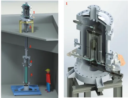
The KROTOS facility is dedicated to FCI (water as coolant) understanding. It has been moved from JRC Ispra to Cadarache and has been subsequently modified and improved. Details are given in [6][7][8][9]. KROTOS consists of four main parts (see Figure 4): a radiation furnace (1), the release tube (3), the test section (5) and the X-Ray radioscopy system.
Figure 1. VITI experimental assembly for heating test in a crucible [3]: (1) VITI chamber, (2) crucible, (3) sample, (4) support for crucible, (5) graphite susceptor, (6) thermal shield, (7) induction coil, (8) pyrometer for sample temperature, (9) pyrometer for crucible temperature, (10)
data acquisition, (11) picture of the assembly.
Figure 2. VITI oxidizing atmosphere set up.
The radiative furnace is a controlled atmosphere vessel consisting of eight concentric shields, which are placed around the cylindrical tungsten heater element, which encloses the crucible containing the melt material (1 liter only in the past, 1.5 liter maximum now). After having reached the desired melt temperature (up to 3000 K), the crucible is released thanks to a pneumatically operated release hook. It falls down in the 4 m long release tube until the impact on a puncher located at the top of the test section, permitting the corium to flow down to the test section through a melt release cone. The test section is a pressure vessel with a test tube inside containing water (200 mm inner diameter, ~1.6 m height), both are made of Fortal, a low-density Al alloy characterized by a low attenuation of X- Ray radiation. There are some different designs depending on the studied phenomena: the bottom of the test section enables to study steam explosion (section 2.2.1) or to characterize mixing (melt and void distribution) and debris bed (section 2.2.2).
Note that the top of the furnace also enables to perform aerosol test (section 2.2.3).
Figure 4. 3D drawing of KROTOS facility. radiative furnace (1), rapid-acting ball valve (2), release tube (3), puncher and release cone (4), test section (5).
Some instrumentation of the test section is the same for 2.1.1 and the 2.1.2 configurations (Figure 5). An optical bi-chromatic pyrometer monitors the temperature of the melt just before entering into the water and a high-speed video recording system visualizes the melt release conditions at 1595 mm level through a view window. The propagation of the melt in the test tube is tracked by sacrificial thermocouples positioned along the central axis. Several lateral K-type thermocouples are used to measure temperature of the gas atmosphere and temperature of the water in the test tube. Sacrificial K-type thermocouples are also used to detect the position of the melt jet leading edge before and during its penetration into the water, and to follow the premixing. The gas pressure variation within the test vessel is measured by piezo-resistive pressure transducers installed on the wall of the test vessel. A TDR-type (time domain reflectometry) probe is used for the water level measurement. A mass spectrometer measures the hydrogen production. The distribution of corium, void and water is obtained from a X-Ray radioscopy system with different set ups (X-Rays 1 or 2 position on Figure 5). It uses a high-energy X-ray source (Linatron of Varian, 9 MeV) (see details on Figure 8).
Figure 5. Test section of KROTOS facility and its instrumentation.
Figure 6. Design of the bottom of the test section to study the steam
explosion.
Figure 7. Design of the bottom of the test section to characterize the debris
bed.
Figure 8. KROTOS X-Ray radioscopy system. 1: X-ray source; 2: lead collimator; 3: test section; 4: scintillator; 5: mirror; 6: opaque box; 7: lead screen; 8: CCD camera. Top view
on left. X-Ray 1 position is represented on right.
X-rays passes filters to avoid the image oversaturation and to harden the beam, the lead collimator to decrease the image noise by suppressing significant amount of scattered radiation, and penetrates the test section and test tube. The transmitted radiation hits the scintillator screen, which converts the X-rays into visible light. A corresponding intensity image in visual spectrum is formed on the rear side of the screen
O 392 878 248 200 368 144° 1 2 3 4 5 6 7 8
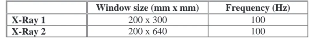
-inside the opaque box. The box contains a mirror and a high sensitive grey level CCD camera. The camera is rotated by 90° on the axis of the X-ray source and protected by a series of lead screens, in order to avoid direct radiations and minimize the scattered ones falling onto the CCD matrix of the camera. Table 1 gives the characteristic of the set up regarding visualization window size and acquisition frequency. The 9 MeV Linatron source is used through a new configuration allowing emitting impulses and having an acquisition with a new CCD camera at 100 Hz (it was only 55 Hz in the past). The lower position of the Linatron provides a larger window of visualization for more information during the premixing and the debris bed constitution.
Table I. Characteristic of X-Ray set up
Window size (mm x mm) Frequency (Hz) X-Ray 1 200 x 300 100
X-Ray 2 200 x 640 100
2.2.1 KROTOS FCI facility to study steam explosion
This configuration is devoted to the study of steam explosion propagation and energetics with prototypical corium melt [6]. The design of the bottom of the test section is given on Figure 6. A pressurized gas trigger device is positioned and is used to trigger the steam explosion after the premixing phase of the FCI. The gas chamber volume of 30 cm3 can be charged to a pressure up to 150 bar and is closed by a steel membrane. A pneumatically activated device cuts the membrane and delivers pressure pulse propagation vertically upwards through the mixture of melt, water and steam and destabilizes the vapor film around the corium droplets. Dynamic pressure transducers (0-100 MPa, 140 kHz) are mounted at the inner surface of the test tube to follow the propagation of the provoked steam explosion. A force transducer (0-1.2 MN) is mounted beneath the test tube to measure the reaction force during the FCI. The X-Ray radioscopy (X-Ray 1 position on Figure 5) gives the distribution of corium, void and water during the premixing and the steam explosion [9].
2.2.2 KROTOS FCI facility for characterization of premixing phase (melt and void distribution)
The understanding of the premixing mechanisms still remains a challenging task because the conditions of the premixing impose directly the efficiency of the explosion. The fine characterization of the premixing phases (corium, void and water) is one of the key parameters to answer to the steam explosion fine quantification needed for the reactor calculations. This configuration (Figure 7) provides the maximum information of premixing and debris bed during FCI. The sacrificial thermocouples enable to follow the premixing propagation, the water level transducer enables to calculate the void fraction and we obtain the distribution of corium, void and water during the premixing with the X-Ray radioscopy system (X-Ray 2 position on Figure 5). At the bottom of the test section, a plane cylinder is mounted to observe the formation of the debris bed, and to measure its temperature. Before post-test physical and chemical analyses of the debris, sieving is done in order to obtain a first estimation of the final granulometry of the corium debris (steam exploded or fragmented) [16].
2.2.3 KROTOS aerosol facility
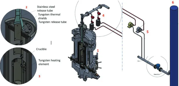
This configuration is used to study the thermal exchanges, thermo-physical interaction and aerosol release. No tests have been performed yet with this new device. Only the top of the furnace is modified (Figure 9). The crucible containing the melt material is held in place by means of the upper tungsten
thermal screens (3). A tungsten release aerosol tube (2), with the same diameter of the crucible, cross the upper shields to collect the gas. At the end of the release aerosol tube, 2 gas sampling assembly are mounted (4). When the pressure valve is opened, because of the pump (5), the aerosols are collected on impactors. The impactor includes several filters for separating the type of aerosols. Chemical and materials post-test analyses are performed on each filter.
Figure 9. Design of the KROTOS aerosol facility: Radiative furnace (1), tungsten release aerosol tube (2), system to held in place the crucible (3), 2 gas sampling assembly with
pressure valve and impactor (4), 2 pump (5), nuclear vent line (6)..
2.3. VULCANO
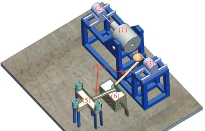
VULCANO facility (Figure 10) is mainly composed of a plasma arc rotating furnace, separate induction furnaces utilized for melting metals, and a test section that can be adapted to the peculiarities of each experimental program. The rotating furnace (1) enables to melt up to 90 kg of oxidic coriums of various compositions at 3000 K maximum temperature. Two graphite plasma torches (2)(3) are ignited by an electrical short circuit. The main arc is then created between the two torches, in an argon/nitrogen atmosphere. The maximum power is about 300 kW in our operating conditions. Corium initial materials are introduced as powders into the furnace which has been prepared with a zirconia insulation layer. The larger masses are melted in two heating steps. When the total energy deposit in the load and temperature at the surface of the corium (measured with pyrometers) reach the target values, pouring can occur. For the study of metallic oxidic corium, three induction furnaces (5) of 1 liter each (about 8 kg of steel) can be used to melt metals. The furnace crucibles are made of sintered refractory cement. The liquid oxidic and metallic melts are then poured in the test section through transfer funnels (4) in the test section. The test section showed on Figure 10 is relative to MCCI experiments.
2.3.1. Corium spreading program [10]
For the study of corium spreading, the test section consists of a spreading plane. It can be made of refractory bricks (e.g. zirconia or magnesia) and of a steel plate or concrete. Two geometries have been used: spreading in an open square or in a 19° angular sector (Figure 11). The spreading section limits are
materialized by refractory magnesia bricks. The test section is mounted on a weighing scale in order to measure the pouring flow rate. Temperature measurements are performed by thermocouples, two-colors pyrometers and infrared thermography. Spreading progression and front velocity are measured with geometrically calibrated cameras.
Figure 10. VULCANO facility: (1) furnace, (2) cathode plasma torch, (3) anode plasma torch, (4) pouring system, (5) furnaces for metals, (6) test section.
Figure 11. VULCANO-E configuration for corium spreading experiments.
2.3.2. Coolability program [11]
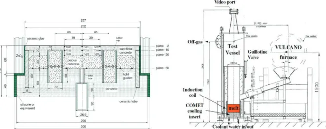
The coolability program consisted in validating the COMET bottom-flooding core-catcher with prototypic corium. A unit cell of the cooling device (Figure 12) was used in the VULCANO facility in a 25 cm diameter, 60 cm high zirconia crucible with about 40 kg corium melt poured from the arc plasma furnace. From bottom to top in different layers, the COMET cell is made of structural concrete, porous concrete which is connected to the water piping system and is filled with water, “sacrificial” concrete ensuring leak tightness, two porous concrete tubes connecting the porous concrete to the middle level of the sacrificial concrete. A dedicated test section has been constructed for this test. An inductor coil was installed around the zirconia cylinder, which was surrounded by a concrete cylinder, inside a fiber-reinforced resin shell. This cylindrical test vessel is topped with a metallic shell connected to the off-gas line. This gas line is connected to a steam condenser and a gas analysis circuit leading to a mass spectrometer. There has been up to now one VULCANO COMET test.
(1) (2) (3) (5) (6) (4) ) ) (4))
Figure 12. COMET test insert installed in the VULCANO test section (left) and VULCANO test vessel (right).
2.3.3. MCCI program [12][13]
The test sections for the study of corium and concrete interaction are made of concrete blocks with a Ø300 x 250 mm hemicylindrical cavity in which corium is poured (Figure 13). The cavity is closed with a zirconia plate of about 10 mm thickness. Induction coils surround the section and provide sustained heating in the corium pool formed in the crucible. Temperature measurements are carried on to trace the ablation front in the concrete. For this last purpose, the test section is equipped with 129 K-type thermocouples that are positioned before concrete casting. The sensors are located on 3 azimuths at 0°, 45° and 90° angles. Some high temperature type C thermocouples are installed in oxydic configuration to measure the temperature of the pool. Pyrometers are also used to measure the pool surface temperature. Details about temperature measurements were presented in [14].
Figure 13. MCCI VULCANO concrete test section 3 MAJOR RESULTS ON PROTOTYPIC CORIUM BEHAVIOR
3.1. CORIUM PROPERTIES
In the framework of severe accident studies, accurate data for the thermo-physical properties are necessary to model the corium behaviour (thermal-hydraulics, physico-chemistry, etc…) at different steps
during the various stages of severe accident progression (steam explosion, in-vessel interaction, corium concrete interaction, corium spreading,…) and for use in severe accidents codes. Up to now, VITI facility has been used in order to measure thermo-physical properties of corium melt simulant in the equivalent system Al2O3-ZrO2. Density, surface tension and viscosity have been measured on 4 mixtures
zirconia-alumina and for pure zirconia-alumina. For pure zirconia-alumina, results are consistent with previous results obtained in the literature [15].
As an example, thanks to the ability of KROTOS to use a wide variety of materials and CEA advanced capabilities for post-test physical and chemical analyses of the resulting debris, such analyses recently revealed the different physico-chemical behaviors between alumina and corium [16]. This has to be investigated further to determine the possible contribution of the materials to the reduced energetics observed with corium melts with respect to alumina melts and to help understanding the “material effect”.
3.2. FCI [17][18]
Seven KROTOS tests have been performed using prototypical corium representative of reactor case conditions. New results have been obtained to explain the key phenomena responsible for steam explosion energetics. According to reactor case scenarios and nature of the reactor (PWR, BWR), different corium compositions can be formed. In the frame of SERENA-2 program, it has been shown that the material effect plays an important role on steam explosion energetics. The so-called “eutectic” corium (70 w/o UO2– 30 w/o ZrO2) and “non-eutectic” corium (80 w/o UO2– 20 w/o ZrO2) have closed behavior
with a slight increase of the energetics rate for the “non-eutectic”. The so-called “sub-stoichiometric” (U,Zr)O2-x has low energetics rates for steam explosion, but produce a high amount of non-condensable
gazes (hydrogen). The production of hydrogen during FCI for some corium composition seems to have an impact on the stability of steam film around corium droplets and also on the void fraction, so meaning different steam explosion energetics. Corium composition with large or small interval of solidification have high energetics rate for steam explosion. The local void production and spatial distribution plays also an important role in the understanding and modelling of steam explosion. For this reason, CEA has developed specific instrumentation using high X-Ray source able to characterize locally void and corium droplets size distribution [9]. But clearly, at the end of SERENA-2 program, some issues regarding material effect on steam explosion energetics have not yet been closed.
3.3. CORIUM SPREADING
Twelve high-temperature dry spreading tests have been performed with either zirconia–alumina mixtures, simulant materials where HfO2 simulated UO2, or prototypic corium with up to 80 wt.% of depleted
UO2 [6]. Significant differences have been observed in simulant and prototypic corium in particular on
physico-chemistry processes, underlining the importance of studying prototypic corium. The main experimental results are the good spreadability of corium-concrete mixtures even for the more viscous ones (with large quantity of silica) and that the spreading is not affected by concrete ablation. Spreading models and codes have been validated and clearly show the efficiency of dry spreading.
3.3. MCCI
A total of 12 experiments have been conducted on VULCANO in order to study MCCI issues. The main result concerning dry oxidic corium tests [12][13] is that silica-rich concretes present an anisotropic ablation, contrary to limestone-rich concretes. This behavior is quite reproducible and can be described with our calculation tool, provided an empirical anisotropy factor is assumed. Today, despite the numerous experimental results, the phenomenology of this anisotropy is not explained. Dry tests performed with oxidic – metallic corium [13][19] have also shown unexpected results regarding steel oxidation and phase repartition. For both kind of corium, analytical research is needed to understand the causes of the observed phenomena in order to assess their effects at reactor scale.
The COMET coolability experiment performed in the VULCANO facility has contributed to validate the COMET PCA core catcher concept with prototypic corium and sustained heating [11].
4 FUTURE DEVELOPMENTS ON THE PLINIUS PLATFORM 4.1. PREMIXING PROCESS DURING FCI [11] [12]
Thanks to the development of a specific post-treatment for the radioscopy [7][8][9], very important information are obtained on the physic of the premixing phase: jet fragmentation process, particle sizes and velocities, phase distribution in the system (corium, steam, liquid water).
We have investigated the improvement of this X-ray radiography system in order to increase the acquisition frequency, the sensibility and the local information. We have already increased the acquisition frequency with the Linatron system, as well as put a second measurement position (see section 2.2). In order to have the whole premixing view of the test section and obtain a better precision of the corium fragments and the vapour film, it is planned to use another X-ray source. One solution would be to use an Oriatron-6 MeV source, with CCD cameras at 200 Hz, on a visualisation window of 200x300mm (Figure 15). Thus, we could have both the Oriatron measurement line at the upper position (X-Ray 1 on Figure 5) and the Linatron measurement line at the lower position (X-Ray 2) (Figure 14).
Figure 14. X-Ray radioscopy LINATRON. Figure 15. X-Ray radioscopy ORIATRON.
4.2. CORIUM COOLABILITY
Even though molten core concrete interaction is a rather slow process that cannot lead to early releases of radioactive material, a late release cannot be excluded if the corium pool is not satisfactorily cooled. Two mitigation processes can be applied: top-flooding of the corium pool or bottom-quenching as already studied. We are currently designing a new experimental configuration for top flooding that stands on ANL SWWICS experiments principle [20], extending the study of water ingression cooling to oxidic metallic corium. Indeed, its physical properties as conductivity, permeability, mechanical properties are not the same as oxidic corium and can affect the corium pool cooling efficiency. Moreover, we aim at carrying out top flooding tests with induction sustained heating to study the effect of gases coming from concrete ablation on cooling efficiency.
4.2.1. Principle of the experimental device
Contrary to previous VULCANO experiments, the corium melted thanks to a thermitic reaction [21]. A quantity of about 80 kg of powder should provide a corium pool of about 30 cm diameter and 15 cm
thick. The principle of the experiment is shown on Figure 16. The device will be composed of an instrumented cylindrical test section made of a fixed upper part and a flexible and moving lower part containing the crucible for corium. In order to determine the efficiency of top quenching, the water vapor generated after flooding will be quantified through a vapor line made of a condenser and water tank. The apparatus will be equipped with two bubbler tanks. The first one will operate in normal functioning and will enable to cool gases from thermitic reaction and to proceed to evacuation of H2 formed during this
reaction as well as during flooding of metallic corium. The second one will operate in case of overpressure in the test section. The experimental device should be operative in 2017.
Figure 16. Principle of future top flooding experimental devices.
4.2.2. Induction system
Since the end of 2014, we have installed a new induction generator on the PLINIUS platform in order to replace the former generator used for MCCI experiments. The nominal power is 400 kW and the frequency can be set between 80 and 300 kHz (the former generator power was 250 kW and optimized frequency was ~44 kHz). Figure 17 represents maximum power values depending on the frequency and on the electrical conductivity of corium that could be obtained with the new generator for two configurations: the hemi-cylindrical cavity of MCCI test sections (300 mm diameter, see 2.3.3) and a cylindrical cavity of 350 mm diameter. These calculated curves show a larger range of heating power than formerly (curve at 44 kHz).
4.2.3. Thermite processing
Uranothermite compositions have been studied on PLINIUS in the past, in particular in the frame of CORITER European program [21]. It has been possible to develop a safe and reproducible experimental process for synthetizing prototypic corium. Several compositions have been studied (as Zr/Fe2O3 + U3O8
and Zr/CrO3 + U3O8). In a first step (intermediate scale), 11 kg of prototypical corium have been
synthetized and melted at 3000qC in less than 30 s and in a second step 45 kg of corium representative of a French nuclear reactor have been synthetized and melted at 2850qC in about one minute. The objective is now to prepare larger amounts of thermite (80 kg) in a dedicated workshop equipped with glove boxes.
MCCI hemi-cylindrical configuration : 300 mm inner diameter Cylindrical configuration : 350 mm inner diameter with 200 mm thick concrete around
Figure 17. Maximum power values available with the new induction generator as a function of corium electrical conductivity and generator frequency: 44 kHz corresponds to the former
generator.
5 CONCLUSIONS
The CEA PLINIUS prototypic corium platform is a research tool dedicated to severe accident studies issues. Its main characteristics are: 3 facilities at different scales – VITI, KROTOS, VULCANO, a large range of masses from a few grams to a few tens of kg, different corium melting techniques (radiative, resistive, inductive heating techniques or chemical reaction), possibility to provide sustained heating to corium pool with inductive heating in MCCI experiments, an efficient X-Ray radioscopy system for the characterization of the main important phenomena during FCI. All these technologies enable to cover a large scope of issues and to adapt to research needs.
PLINIUS platform is proposed in a transnational access program that offers access of EU users to 18 severe accident research facilities in Europe. This is organized in the frame of SAFEST (Severe Accident Facilities for European Safety Targets) project under European Program FP7. The objective of SAFEST is creation of an integrated pan-European laboratory for severe accident research able to address and successfully resolve the variety of the remaining severe accident issues related to nuclear power plant severe accident analysis and corium behavior. PLINIUS is also participating to the ALISA project European program FP7 which aim is to provide a transnational access to research facilities in Europe and in China to allow the optimal use of the resources in the complex field of severe accident analysis.
A new larger corium facility PLINIUS 2 [22] is being designed to replace the current PLINIUS platform after 2020. PLINIUS-2 will provide larger mass capabilities for further experimental works on corium, based on the experience from 20 years prototypic corium operation in PLINIUS.
ACKNOWLEDGMENTS
Currently, PLINIUS platform is part of the Research Infrastructures supported by the European Atomic Energy Community through 7th Framework Projects ALISA and SAFEST (grant agreements 295421 and 604771). Some of the activities are performed with the financial help of the French government through the “Programme d’Investissement d’Avenir” (Grants ANR-11-RSNR-0014 and ANR-11-RSNR-0010).
REFERENCES
1. C. Journeau et al., “Severe accident research at the PLINIUS prototypic platform”, Proceedings of
2. P. Piluso et al., “Severe Accident Experiments on PLINIUS Platform Results of First Experiments on COLIMA Facility Related to VVER-440 - Presentation of Planned VULCANO and KROTOS Tests”,
Proceedings of International Conference Nuclear Energy for New Europe 2005, Bled, Slovenia
(2005).
3. P. Piluso et al., “Hafnium dioxide for porous and dense high-temperature refractories (2600 °C)”,
Journal of the European Ceramic Society, 29, pp. 961---968 (2009).
4. K. Plevacova et al., “Zirconium carbide coating for corium experiments related to water-cooled and sodium-cooled reactors,” J. of Nuclear materials, 414, pp. 23-31 (2011).
5. P. Piluso et al., “Viscosity measurements of ceramic oxides by aerodynamic levitation”, Int. J.
Thermophys., 23 (5), pp. 1229-1240 (2002).
6. N.Cassiaut-Louis et al., “KROTOS KS-6 test data report”, OECD/SERENA-2012-TR11 report
(2012).
7. N.Cassiaut-Louis et al., “X-Ray visualization and quantitative measurements of the premixing phase during KROTOS Corium water interaction experiments”, Proceedings of International Conference on
Advancements in Nuclear Instrumentation Measurement Methods and their Applications (ANIMMA),
Marseille, France (2013).
8. C. Brayer et al., “Analysis of the KROTOS KFC test by coupling X-Ray image analysis and MC3D calculations”, Proceedings of ICAPP ’12, Chicago, IL, USA, June 24-28 (2012).
9. C. Brayer et al., “Application of X-Ray radioscopy for investigations of the 3-phase-mixture resulting from the fragmentation of a high temperature molten material jet in water”, Proceedings of 8th
International Conference on Multiphase Flow ICMF 2013, Jeju, Korea (2013).
10. C. Journeau et al., “Ex-vessel corium spreading: results from the VULCANO spreading tests”, Nucl.
Eng. Des., 223, pp. 75-102 (2003).
11. C. Journeau et al., “Validation of the COMET Bottom-Flooding Core-Catcher with Prototypic Corium”, Proceedings of ICAPP’06, Reno, USA (2006).
12. C. Journeau et al., “Two dimensional interaction for oxidic corium with concretes: the VULCANO VB test series”, Ann. Nuc. Ener., 36, pp. 1597-1613 (2006).
13. C. Journeau et al., “Contributions of the VULCANO Experimental Programme to the Understanding of MCCI Phenomena”, Nucl. Eng. Technol., 44, 33, pp. 261-272 (2012).
14. V. Bouyer et al., “High temperature measurements in severe accident experiments on the PLINIUS Platform”, Proceedings of International Conference on Advancements in Nuclear Instrumentation
Measurement Methods and their Applications (ANIMMA), Marseille, France (2013).
15. D. Grischenko, “Recent progress in the gasfilm levitation as a method for thermophysical properties measurements: application to ZrO2–Al2O3 system”, High Temp.-High Pressures, 40 (2), pp. 127-149.
(2011).
16. V Tyrpekl et al., “Material effect in the nuclear fuel–coolant interaction: analyses of prototypic melt fragmentation and solidification in the Krotos facility”, Nuclear Technology, 186, (2014).
17. OECD Research Program on Fuel-coolant Interaction, Phase 1 Final Report (Synthesis of Phase 1 finding), July, (2006).
18. OECD/SERENA-Final seminar, CEA-Cadarache, November 2012.
19. J.J. Foit et al., “Experiments on MCCI with oxide and steel”, Ann. Nucl. Ener., 74, pp. 100-109 (2014).
20. S. Lomperski et al. “Experimental evaluation of the water ingression mechanism for corium cooling”,
Nucl. Eng. Des., 237, pp. 905–917 (2007).
21. Piluso et al., “Uranothermic Reaction as an Efficient SHS Process to Synthesize Severe Accident Nuclear Materials”, Intern. J. Self-Propagating High-Temperature Synthesis, 18, 4, pp. 241–251 (2009).
22. C. Journeau et al., “PLINIUS-2: A New Versatile Platform for Severe Accident Assessments”,