HAL Id: cea-03254586
https://hal-cea.archives-ouvertes.fr/cea-03254586
Submitted on 8 Jun 2021HAL is a multi-disciplinary open access
archive for the deposit and dissemination of sci-entific research documents, whether they are pub-lished or not. The documents may come from teaching and research institutions in France or abroad, or from public or private research centers.
L’archive ouverte pluridisciplinaire HAL, est destinée au dépôt et à la diffusion de documents scientifiques de niveau recherche, publiés ou non, émanant des établissements d’enseignement et de recherche français ou étrangers, des laboratoires publics ou privés.
Characterization of a medical interface
A. Janot, C. Bidard, M. Gautier, F. Gosselin, D. Keller, Y. Perrot
To cite this version:
A. Janot, C. Bidard, M. Gautier, F. Gosselin, D. Keller, et al.. Characterization of a medical interface. 2007 IEEE International Symposium on Industrial Electronics, Jun 2007, Vigo, Spain. pp.2071-2076, �10.1109/ISIE.2007.4374927�. �cea-03254586�
Characterization
of a medical
interface
A. JANOT"2),
C.BIDARD(l),
M.GAUTIER(2)
(1)CEA/LIST Interactive Robotic Unit
18 routedu Panorama, BP6,92265 Fontenay aux Roses
Cedex, France
alexandre.janotgcea.fr,
catherine.bidardwcea.frAbstract- The medical interface studied in this paper is an haptic interface. These interfaces are robotic devices intended to enhance theuser'simmersion in virtual environments through the stimulation of the haptic sense. Usually, they consist of an
articulated mechanical structure which introduces distortion between the operator and theexplored world. In orderto assess
the qualityof the devices, it must be identified. This paper deals with this issue and introduces the characterization of the medical interface. Each 3 degrees of freedom (DOFs) branch uses a
parallelogram and double parallelogram loop. The characterization is based onthe inverse model and least squares method.
I. INTRODUCTION
Haptic interfaces aim at the matching between the force and
displacements given bytheuserand thoseappliedtothe virtual world. Such systems are in growing demands for applications
such as force feedback remote-control systems for extreme environment, man-machine interaction and training in
professional operating procedures [1].
Usually, haptic interfaces consist ofa mechanical actuated structure, such asrobots, whose distal link is equipped with a
handle. When manipulating this handle to interact with the
explored world the user feels a distortion introduced by the
dynamic model of the interfaces. This distortion must be identified in order to enhance thedesignof the device and/or to
develop appropriatecontrol laws.
To do so, the system is often modeled as a second order,
sometimes with Coulombfriction, asin[2]-[3]. Ithas also been modeled as aseries of second orders [4]. Severaltechniques of identification have been tested: in [5] the authors identifythe device using spectral analysis while pulses are used in [4] to
characterize another haptic device and in [6], a parallel
interface device is identifiedbymeans of relative least squares method and inverse model. Inall
cases,
the distortion islocallyidentifiedrelying on specificmodels. In our case, the medical interface exhibitsacomplexarchitecture andastrongnonlinear behavior. Thus, these techniques can not be applied as they
would not allow characterizing the interface in different
positions of the workspace. Therefore, the link parameters
mustbe identified.
In [7], a
PHANToMTM
was identified using inverse model and least squares method. However, the conditioning numberF.
GOSSELIN(l),
D.KELLER('),
Y.PERROT(')
(2)IRCCyN, Robotic team
1, rue de la Noe - BP92 101 - 44321 Nantes Cedex 03, France
maxime.gautiergirccyn.ec-nantes.fr,
florian.gosselinwcea.frof the linear regression is not considered. Hence, it is impossible to know if the trajectories are enough exciting.
In [8]-[9], a parametric identification method adapted to multi DOFs systems, based on inverse model and least squares regression has been successfully applied to industrial robots. This method has been extended to a single DOF haptic interface using a cable transmission. The first results were encouraging [10]. Our purpose is to extend this result to 3 DOFs haptic devices. Therefore, we model and identify the 3 DOFsbranches of a medical interface which exhibit a complex architecture consisting of a single and a double parallelogram
loop.
The paper is organized as follows: the second section presents the medical interface and its modeling while the identification method and the experimental results are presented in the third section; finally, the performances will be discussed in section 4.
II. PRESENTATIONAND MODELING OF THE MEDICAL INTERFACE
A. Presentation
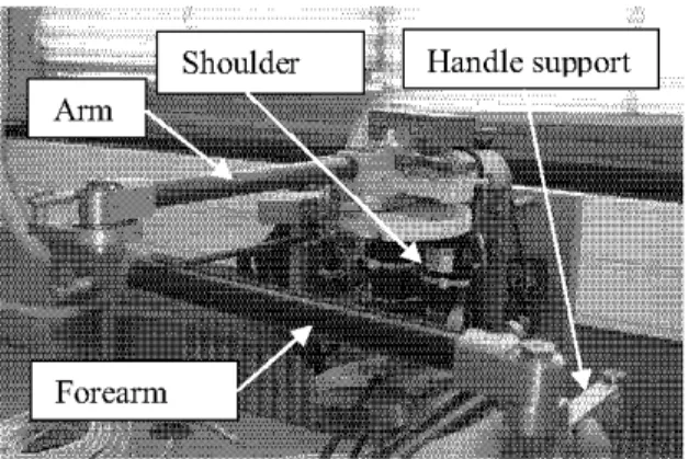
The CEA LIST hasrecently developeda 6DOFhigh fidelity haptic device for telesurgery [12]. As serial robots are quite complexto actuatewhile fully parallelrobots exhibitalimited
workspace, this device makes use of a redundant hybrid architecture composed of two 3 DOFs branches connected via a platform supporting a motorized handle, having thus a total of 7 motors (Fig. 1).
Each branch is composed of a shoulder, an arm and a forearm lever actuated by a parallelogram loop (Fig. 2). To provide a constant orientation between the support of the handle and the shoulder, a double parallelogram loop is used. Our purposeis to model and identify the serial upper and lower branches of the interface (the handle is disconnected).
* qa=
[q1
q2q5]T
the activejoints
position
vector* qp=
[q3
q6 q4 q7 q8qs]T
the passive joints position vector* qc=
[q1o
q11q12]T
thecutjoints
position
vector* Far
[Far,
Far2 Far5 Far3 Far6 Far4 Far7
Far8
Farg]T
thejoints
torque vectorof the equivalent tree structure
* Fm=
[F,
F2
F5]T
the motorizedjoints
torques02 X77 xi Xg \ Lg N; \°12 q4 \ q12 :q5-TT \ y4 XX3 4
Fig. 2. Upper branchotthemedicalintertaceto beidentified
Fig. 4. DHM frames for modeling the double parallelogram loop of the
branches of the medical interface
B. Modeling
Inthis section, the modeling of the upper branch is presented
(the modeling of the lower branch being the same). Fig. 3 presents the modified Denavit Hartenberg (DHM) frames of the single parallelogram loop actuating the forearm whileFig. 4 presents the DHM frames of the double parallelogram loop which is modeledas a series of twoparallelograms attached to
a common mechanical piece. This point of view can be consideredas anextension of thereasoning exposedin[ 1].
Z3 Z10,Z13 z2,z5 Z
x~~~~~~~ALA
d6,,
z410~~~~~~~~6
x5Fig.3.DMfae5od oeigtesnl aallga opo h
Inorde tooti neuvln resrcue ons1,1
L3
an x2arzitalzu 13.Wt epc o h on ubr
q3111~2-4
L~
/L5Fig. 3. DHM frames for modeling the single parallelogram loop ofthe branches of the medical interface
In order to obtain an
equivalent
tree structure,joints
10,
11I
and 12are
virtually
cut[
13].
Withrespect
tothejoint
numbers defined onFig. 3 andFig. 4,we denote for theequivalenttree structure:Now, the relations between the variables
q.
and qp are calculated. These relations constitute the geometric constraintequationsof the closedloops,i.e. qp=fc(qa)andparallelogram loops give linear constraint equations [11]. Since the links 2, 6 and 7(resp. 5, 3and9)arealways parallel,weobtain:
q3=qs-q2-K
(1)
q6 = q2- q5 q7= q2qg
= /2+q5 (2)(3)
(4)
Link 4and 8keep a constant orientation with respect to the shoulder. Thatgives:
q4 = 3
/2
-q5q8= /2-q2
Finally,the closedloop equations give: qlo q5 -q2-7 ql1I -q2 ql2 =3t /2-q5
(5)
(6)(7)
(8) (9) Knowing the constraint equations, the dynamic model of theclosed
loop
chainisgiven by:
FM
=[L
a
0Frar
=[3
G
]
arI 0 0 00 00O jO
Fm = O 1 0 -1 I 0 1 -I
Far
0
O
1 1 -1 -1 0 0 1(10) Thus, (10) describes the couplings in the 3 DOFs branches of the medical interface. Thanks to the constraintequations, the dynamic model can be written as:
=A(qa)qa + H(qa 9a) +Fyqa+Fcsign(qa) + offset
(1 1)
Where,
qa,
qa
andqa
are respectively the active jointsposition, velocity and acceleration vectors, A(qa) is the inertia matrix, H(qa,
qa)
is the vectorregrouping Coriolis, centrifugal andgravity torques,F,
andF,
arerespectively the viscous and Coulomb friction matrices and offset is the offset torques vector.The classical parameters used in (11) are the components
XXj,
XYj, XZj, YYj, YZj, ZZj
of the inertia tensor of link j denotedJJj,
the mass of the linkj calledmj,
the first moments vectorof link j around theoriginof framejdenoted j =[MXj
MYj
MZJJT,
and the friction coefficientsfvj, fcj.
For the motorizedjoints,weadd the actuator inertia calledlaj.The kinetic and potential energies being linear with respect to the inertial parameters, so is the dynamicmodel. It can thus be written as:
F=
D(qa, qa,qa)X
(12)Where
D(qa,qa,
q9a)
is a linear regressor and X is a vector composed of the inertial parameters. In the following, thesubscript "a" is missing because only the active joints are considered.
C. Baseparameters
The set of base parameters represents the minimum number of parameters from which the dynamic model can be calculated. Theycanbe deduced from the classical parameters
by eliminating those which have no effect on the dynamic
model and by regrouping some others. In fact, they represent the onlyidentifiable parameters. In [14] a direct and recursive method of calculation of minimum parameters is described. This method is programmed in SYMORO+ and it is efficient for robots havingserialor tree structures. Forclosedloops,the minimum inertial parameters of the equivalent tree structure are a subset of those of the closedloops. Generally, additional relations from the constraint equations occur. These
regroupings may be found using the QR decomposition
numerical method [15] ordealingwith theanalytical equations.
Some particular closed loop structures, as parallelogram,
enable easier parameterregroupings [11]. In ourcase, wehave calculated the base parameters through the analytical method and compared with those given by the numerical method. There is no difference. Hence, wegivethe base parameters and theregroupingrelations.
The base parameters are:
ZZIR,
MXIR,
MYIR,fvl, fcl,
offset,,
XX2R, XY2R, XZ2R, YZ2R,ZZ2R, MX2R, MY2,
fv2R, fc2R,
offset2, XX3R,XY3R, XZ3R, YZ3R,ZZ3R, MX3R, MY3,
fv3R, fc3R, MY4, MX5R, MY5, fv5R, fc5R,
offset5, MY6, MY7, MY8R. The regrouping relations are:
ZZIR
ZZ1+YY2+YY3-XX4+YY5+YY6+YY7-XX8+YY9+ ...m4d42+m7d72+md
92+(m3+m4+m8+mg)d32+Ial
MXIR
MXI-m7d7+(d7/d3)MX7
MYIR MyI+Mz2+Mz3+Mz4+Mz5+Mz6+Mz7+Mz8+Mz9
XX2R=XX2-YY2-(m3+m4+m8+m9)d32+XX6-YY6+XX7-YY7XY2R=
XY2+XY6+XY7
XZ2R=XZ2-(MZ3+MZ4+MZ5+MZ6+MZ7+MZ8+MZ9)d3+
...XZ6+XZ7YZ2R
YZ2+YZ
6+YZ7
ZZ2R=ZZ2+(m3+m4+m8+m9)d32+ZZ6+ZZ7+la2
MX2R
=MX2+(m3+m4+m8+mg)d3+MX6+MX7
fv2R fv2+ fv7+ fv8+fvl1
fc2R fc2+ fc7+ fc8+ fclIXX3R=XX3-YY3-d42m4+XX5-YY5-d62m6+XX9-YY9
XY3R=XY3+XY5+XY9 XZ3R=XZ3-d4MZ4+XZ5-d6MZ6+XZ9YZ3R YZ 3+YZ5+YZ9
ZZ3R=ZZ3+m4d42+ZZ5+m6d62+ZZ9+Ia5
MX3R
=MX3+m4d4+(d6/d3)MX6+MX9
MY3R
=MY3
+MY9fv3R fv3+ fv6+ fvlo
fc3RfC3+fC6+fC10-MX5R
=MX5+m6d6-(d6/d3)MX6
fv5R fv5+ fv4+
fv9+
fvI2
fc5R fc5+ fc4+
fc9+
fcI2
MY8R
=MY8-(d7/d3)MX7
The parameters having no effect on the dynamic model are:
XXI,
XYl,
XZI,
YYl,
YZI, MZI,
mI, XY4, XZ4, YZ4, ZZ4,XY8, XZ8, YZ8, ZZ8, MX4and MX8.
III. IDENTIFICATIONMETHOD AND EXPERIMENTAL RESULTS
A.
Theoty
Generally, ordinary least-squares (LS) technique is used to
estimate the minimum inertial parameters solving an
over-determined linear system obtained from a sampling of the
dynamic model, along a given trajectory (q,q, q) [8]-[9]. X
being the b base parameters vector to be identified (same vector as X
),
Y the measurements vector (obtained byconcatenation of the torques vector F over the whole
trajectory), W the observation matrix (obtained by
concatenation of the linear regressoroverthe wholetrajectory)
and p thevectorof errors, the system is describedasfollows:
The L.S. solution X minimizes the 2-norm of the vector of errors p. W is a rxb full rank and well conditioned matrix,
obtained by tracking exciting trajectories and by considering
the minimum inertial parameters, r being the number of
samplingsalong atrajectory. Hence, there isonlyonesolution X [9]. Standard deviations
7,
are estimatedusing classical and simple results from statistics. The matrix W is supposed deterministic, and p, a zero-mean additive independent noise,with a standard deviation suchas:
Cp =E(pp )=
2Ir
(14)where E is the expectation operator and Ir, the rxr identity
matrix. An unbiased estimation of (T is:
2 p
Y-wX
(r
-b)
The covariance matrix of the standard deviation is calculated asfollows:
CXX T (16)
2 =C is theith diagonalcoefficient ofC2. Therelative standard deviation
%O
iisgivenby:%5X =100
jr Xj (17)
However, inpractice, W is not deterministic. This problem can be solved by filtering the measurementmatrix Y and the columns of the observation matrix Wasdescribed in [9].
B. Experimentalresults
Exciting trajectories are designed by mixing triangular and sinus trajectories with various frequencies and
amplitudes.
Triangular positions give constant velocities and excite wellgravity and friction parameters, while sinus positions give
sinus accelerations and excite well inertia parameters.
The friction model is identified thanks to the method described in [19]. Itconsists inmeasuring the motorized
joint
torques at different constant velocities. Hence, we have used
triangular
trajectories
with variousamplitudes
andfrequencies.
Experiences show that in our case, nonlinear effects are negligible. Therefore, a classical static model (viscous andCoulomb) is sufficient. Inaddition,itcomesthat the friction of
passivejointsprovestobenegligible.
Appropriate data treatment was designedas in [9] and [20].
For each branch, W is a
(16000x34)
matrix and itsconditioning number is close to 50. The
trajectories
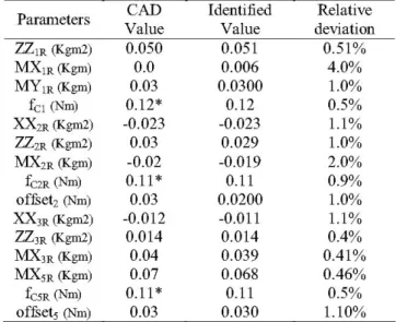
are thusenough exciting for identifying the base parameters of each branch [16]. The identified values of the upper branch are
summed up in Table 1 while the identified values of the lower
branch are summed up in Table 2. Parameters
offset,,
MYj
(exceptedMYIR),
fv3R,
f,3R,
viscous damping andnondiagonalcomponents of inertia tensor are missing because they are
small comparedtothe others. We checked that when identified they have a large relative deviation, and that when removed from the identification model, the estimation of the other parameters is not perturbed. We checked also that inertia and gravityvalues arecompatible with those obtained from CAD.
Direct comparisons have beenperformed. Thesetests consist incomparing the measured and the estimated torquesjustafter the identification procedure. An example for the arm of the lower branch is illustratedFig. 5. We show that the estimated torquefollows the measured torqueclosely.
Cross tests validations have been also performed. They
consist in comparing the experimental data obtained along a trajectorynotused duringthe identificationprocedure and data reconstructed from the identified parameters. Results obtained for the forearm of the upper branch(giveninFig. 6) show that the estimated torque follows the measured torqueclosely.
TABLE1: IDENTIFIEDVALUES FOR THE UPPER BRANCH
Parameters
ZZIR
(Kgm2)MXIR
(Kgm)MYIR
(Kgm) fCI (Nm) XX2R (Kgm2) ZZ2R (Kgm2)MX2R
(Kgm) fC2R (Nm) offset2(Nm)XX3R
(Kgm2)ZZ3R
(Kgm2) MX3R(Kgm)MX5R
(Kgm) fC5R (Nm) offset5 (Nm) CAD Value 0.050 0.0 0.03 0.12* -0.023 0.03 -0.02 0.11* 0.03 -0.012 0.014 0.04 0.07 0.1 1* 0.03 Identified Value 0.051 0.006 0.0300 0.12 -0.023 0.029 -0.019 0.11 0.0200 -0.011 0.014 0.039 0.068 0.11 0.030 Relative deviation 0.51% 4.0% 1.0% 0.5% 1.1% 1.0% 2.0% 0.9% 1.0% 1.1% 0.4% 0.41% 0.46% 0.5% 1.10%TABLE2:IDENTIFIEDVALUES FOR THE LOWER BRANCH
Parameters
ZZIR
(Kgm2) MXIR(Kgm) MYIR(Kgm) fCI (Nm) XX2R(Kgm2) ZZ2R(Kgm2) MX2R(Kgm) fC2R (Nm) offset2(Nm) XX3R(Kgm2) ZZ3R(Kgm2) MX3R(Kgm) MX5R(Kgm) fC5R (Nm) offset5 (Nm) CAD Value 0.046 0.0 -0.04 0.14* -0.021 0.028 -0.025 0.11* 0.03 -0.01 0.012 0.035 0.07 0.10* 0.03 Identified Value 0.046 -0.005 -0.040 0.13 -0.021 0.027 -0.023 0.11 0.020 -0.010 0.012 0.034 0.067 0.11 0.020 Relative deviation 0.65% 11.0% 0.42% 0.30% 1.2% 0.47% 0.95% 0.65% 3.0% 2.1% 0.46% 1.0% 0.5% 0.5% 1.00% 2074 I I IWenotethat theexperimentalresults for the upper and lower branch are close to each other. The differences may be due to small differences between machined parts of the upper and lower branches (due to the symmetrical nature of the two branches, some results are of opposite sign). The symbol *
means that these values have been identified through the method described in [19].
inthe operational space,
Mop
is the(3x3) apparent mass matrix defined byM0p=J'TA(q)J1,
(J is the (3x3) jacobian matrix equals to J=af(q)/aq),Bop
is the apparent viscous friction matrix which equals toB,P=J-TFvJ-
,Kop
is the operationalstiffiess matrix given by
Kop=j-T
KtotJ-1
(Ktot
represents the global stiffness of the device, defined byKtotAq
=JTFop-F)
andFcop=J-TFc
is the operational Coulombfriction matrix. Fd=J- (H(q, q ) -A(q) J q ) 0.6 0 Measured I- Estimaed 060 A t 0.8 4060 4080 4100 4120 4140 4160Fig. 5: Direct comparison validation, comparesthe measured and estimated
torquesappliedtothearmof the lower branch
(19) Fd given by (19), is the torque neglected in the linear characterization ofoperational dynamics of the interface. The greater the velocity and angular range, the higher the disturbance will be.
The apparent mass, the operational stiffness and friction felt
bythe operator, can be calculated at all configurations in the
workspace. In order to illustrate the interest of this approach
the details about the apparent inertia aregiven.
Fig. 7 shows the maximum values of the diagonal
components (called respectivelyMxx,Myy andMzz) obtained
through SVD decompositionof the apparentmassmatrix when q2orq3 varies aroundanatural
operator's position.
KMO KMO 0.72_ 0.7_ 0.68 0.66_ 0.64 _ 0.62_ 0.8 0.6_ 0.5f= -80 -60 -40 MYY 0.4 0.3 -80 -60 -40 MZz -20 -20 0. 125= 0.12_ i 0.115 _ 0.11_ 0.105_ -80 -60 -40 -20 cq2(dege) 50 55 60 65 70 MWY 0.6 -- --I----1-- -t -0.5 0.4 50 55 60 65 70 MAZ 0 19 -0t 18 - - - -0.17 0.16 0 15 0 50 55 60 65 70 q3(degr-s)
Fig. 6: Cross testvalidation, compares the measured and estimated torques
appliedtothe forearm of the upper branch
IV. CHARACTERIZATIONOF THE INTERFACE
Knowingthe values of the minimum inertial parameters, it is
possibleto calculate the apparentmassandoperationalfriction felt by the operator. This characterizes the distortion introducedbythehapticinterface. Inthe operationalspace, the model of each branchcanbe writtenasfollowing:
F0p=Mop
X+Bo.
X+KOp.X+FcOp.sign(
X )+Fd (18)Where
Fop
is the force applied bythe operator, X, X and Xare respectively the position, velocity and acceleration vector
Fig.7.Apparentmassaroundanaturalposition:upperbranch(solid line) and lower branch(dashed line)
When q2 varies while q3 is fixed at a constant position, the maximum weight felt by the operator is close to 710g. This value ismainlyduetothemassesof the extremities of the links
of the structure (see the regrouping formulas). Due to limited
reductionratios, the apparentmassresultingfrom the inertia of therotorsof themotorsislimited,aswellasthe apparentmass
of the counter-weights which are compensating the gravity
effect. Although their masses are close to lKg, their inertial effect is limited dueto their proximitywith the rotation axes.
We observe that the performances are
quite homogeneous.
Hence, whenmoving onlythearmof the medicalinterface, the operator is weakly disturbed by the variation of the apparent
mass.
Measured andestirrdedtorques
O0.
0.2i 0.3
When q3 varies while q2 is fixed at a constant position, the minimumweight felt by the operator is close to 600g. But, the performances are not homogeneous. Thus, when moving only the forearm of the medical interface, the operator is disturbed by the variation of the apparent mass. Indeed, this variation is close to 500g and can reach lKg. So, in order to compensate this undesirableeffect, acontrol law is needed.
Once again, theperformances of the upper branch are close tothose of the lower branch.
Finally, thanks to the identification procedure described
along this paper, we can model the branches of the medical interface exhibiting a complex architecture and evaluate their
performancesateachpointof theworkspace.
V. CONCLUSION
Experimental results given along this paper show that it is
possibletoapplyamodelingand an identification method used for industrial robots for characterizing haptic devices. Indeed,
associated with a proper parametric model, the identified values can be used to evaluate the distortion introducedbythe device. It is thuspossible to assessthequalities and drawbacks of the interface and to improveits design.Itis alsopossibleto compensateadverse effectsby appropriatecontrol laws.
One importantaspectof theproposed methodologyis thatno specific assumption is made. Indeed, the parallelogram loops asall base parametersweretaken intoaccountinthemodeling.
Therefore, the protocol exhibited along this paper can be
appliedtoanyhapticdevice.
The identification protocol exposed along this paper is not limited to mechanical systems. For instance, it was
successfully applied to a synchronous machine in [17] and it
was comparedwith another identification method[18].
However, to apply correctly this identification method, position, current measurements and exciting trajectories are
needed. Inaddition, the identification was made under therigid modeling hypothesiswhich is valid inafrequencyrange[20].
Futureworks concern the use of this method toidentifythe 6 DOFs medical interface. In addition, the structural flexibility
will be identified in order to determinate its influence in the
haptic rendering. Several techniques of identification of localized flexibilities have beendesignedand tested in[20] and could be extendedtomultidegreesof freedom.
REFERENCES
[1] P.A. Millman, M. Stanley and JE. Colgate, "Design of a high
performance haptic interface to virtual environments", IEEEAnnual
Virtual RealitySymposium, 1993, p. 216-222
[2] J. Colgate and G. Schenkel, "Passivity of a class of sampled data systems:applicationtohaptic interfaces",AmericanControlConference, Baltimore1994, p. 3236-3240
[3] N. Diolaitti, G. Niemayer, F. Barbagli and J. Kenneth Salisbury, "A criterion for the passivityofhaptic devices", Proc. IEEEInt. Conf on
Robotics andAutomation,2005, p. 2463-2468
[4] M. Moreyra and B. Hannaford, "A practical measure of dynamic response of haptic devices", Proc. IEEE Int. Conf on Robotics and Automation, Leuven, 1998, p.369-374
[5] A. Frisoli and M. Bergamasco, "Experimental identification and
evaluation ofperformance of a 2 dofhaptic display", Proc. IEEE Int.
ConfonRoboticsandAutomation, 2003,p. 3260-3265
[6] C.D. Lee, D.A. Lawrence and L.Y. Pao, "Dynamic modeling and parameteridentification ofaparallel haptic interface", Proc. 10thSymp.
HapticInterfaces for VirtualEnvironments and TeleoperatorSystems, IEEEVirtual Reality Conf., Orlando,2002, p. 172-179
[7] A.M. Tahmasebi, B. Taati, F. Mobasser and K. Hashtrudi-Zaad, "Dynamicparameteridentification andanalysis ofaPHANToMTmhaptic device", Proc. IEEE Conf on ControlApplications, Toronto, August
2005, pp. 1251-1256
[8] M.Gautier,W.Khalil andP. P.Restrepo,"Identification of thedynamic
parametersofaclosedloop robot",Proc. IEEE onInt. ConfonRobotics
andAutomation,Nagoya, may1995,p. 3045-3050
[9] M.Gautier, "Dynamic identification of robots withpowermodel",Proc.
IEEEInt. Conf on Robotics andAutomation, Albuquerque, 1997, p.
1922-1927
[10] F. Khatounian et al., "Parameter identification ofa single degree of freedom haptic interface", 14th IFACSymp. on System Identification,
SYSID2006,Newcastle, Australia, 2006,p. 249-254
[11] F. Bennis andW.Khalil, "Minimum inertialparametersof robots with
parallelogram closed loop", IEEE Trans. On Systems, Man and
Cybernetics, Vol.SMC21, 1991,p., 318-326
[12] F.Gosselin,C.Bidard,J.Brisset, "Design ofahighfidelity haptic device fortelesurgery",IEEEInt. Conf onRobotics andAutomation, Barcelone 2005,p. 206-211
[13] W. Khalil et J.F. Kleinfinger, "A newgeometric notation foropenand closed loop robots",In: IEEEInt. Conf On Robotics andAutomation,
SanFranciscoUSA,April 1986,pp. 1147-1180.
[14] M.Gautier andW.Khalil, "Direct calculation of minimumsetof inertial
parameters of serial robots", IEEE Transactions on Robotics and Automation, Vol.6(3),June1990.
[15] M. Gautier , "Numerical calculation of the base inertial parameters", JournalofRobotics Systems, Vol. 8,august1991,p. 485-506
[16] M. Gautier andW.Khalil, "Exciting trajectories for theidentification of base inertial parameters ofrobots", In. Proc. Of the 30th Conf on DecisionandControl, Brigthon, England, December 1991,pp. 494-499.
[17] F. Khatounian, S. Moreau, E. Monmasson, A. Janot and F. Louveau,
"Simultaneous Identification of the InertialRotorPosition and Electrical
Parameters ofa PMSM for aHaptic Interface", In. 12th EPE-PEMC
Conference, Portoroz, Slovenia, August September 2006, CD-ROM,
ISBN 1-4244-0121-6.
[18] F. Khatounian, S. Moreau, E. Monmasson, A.Janot and F. Louveau,
"Parameters Estimation of the Actuator Used in Haptic Interfaces: Comparison oftwo IdentificationMethods", In. ISIE2006, Montreal,
Canada, August September2006
[19] R. Specht, and R. Isermann, "On-line identification ofinertia, friction andgravitational forces appliedto anindustrialrobot",Proc.IFACSymp.
onRobotControl,SYROCO'88, 1988,p. 88.1-88.6
[20] M.T.Pham,M. Gautier andP. Poignet, "Identification of joint stiffness with band pass filtering", Proc. IEEE on Int. Conf on Robotics and Automation,Seoul,may2001,p.2867-2872