Development of a Robot Localization and
Environment Mapping System
by
Cynthia Dawn Walker Panas
Sc.B. Mechanical Engineering
MASSACHUSETTS NSTITUTE OF ECHNOLOG -2L1
12 L ... - __-IMassachusetts Institute of Technology, 2007
ARCHIVES
Submitted to the Department of Mechanical Engineering
in partial fulfillment of the requirements for the degree of
Master of Science in Mechanical Engineering
at the
MASSACHUSETTS INSTITUTE OF TECHNOLOGY
February 2012
@
Massachusetts Institute of Technology 2012. All rights reserved.
A uth or ...
/...
...
. ...
Department of Mechanical Engineering
January 6, 2012
7l**
2
C ertified by ...
...
...
...
Kamal Youcef-Toumi
Professor of Mechanical Engineering
Thesis Supervisor
A ccepted by ... . .. wm ...
David E. Hardt
Professor of Mechanical Engineeering
Graduate Officer
Development of a Robot Localization and Environment
Mapping System
by
Cynthia Dawn Walker Panas
Submitted to the Department of Mechanical Engineering on January 6, 2012, in partial fulfillment of the
requirements for the degree of
Master of Science in Mechanical Engineering
Abstract
The intent of this research is to develop a robust, efficient, self-contained localization module for use in a robotic liquefied petroleum gas (LPG) tank inspection system. Inspecting large LPG tanks for defects is difficult, expensive and energy intensive. Replacing the human inspectors with a robotic inspection system will make the in-spection process faster, less expensive, more reliable and safer. The sensing platform designed in this work can collect data about the environment and track the robotic inspection platform, recording the defect locations. It consists of a two axis gimbaled sensing platform with a single point distance sensor placed in the manhole of the tank. A collection of algorithms were developed to use in conjunction with the sens-ing platform to collect and process the 3D data into a map of the environment. The algorithm's main feature is a robust and efficient method of segmenting and fitting data to a right capped cylinder that is faster and more robust to noise than current methods. The improved performance comes from a unique combination of object shape knowledge, the Gauss image and 3D histogram techniques which achieve accu-rate segmentation without iteration. The hardware and software were demonstaccu-rated to function robustly in a noisy environment. The unique ability of the system to work in an LPG tank allows it to be integrated into a robotic inspection system that can remove the majority of the cost and risk associated with LPG tank inspection. Thesis Supervisor: Kamal Youcef-Toumi
Acknowledgments
This work was made possible through the topic suggestion and financial support of the Qatar National Research Fund. I would like to thank Dr Uvais Qidwai for his insight into the project details and continued work on the funding paperwork.
I would like to thank my Professor, Kamal Youcef-Toumi, for his insight into
difficult problems and his trust in me to carry out my work as I believe necessary. I would also like to thank him for his support during my father's illness and eventual passing. Professor Youcef-Toumi was very understanding and his flexibility with my work made that horrible time easier.
I would also like to thank my fellow graduate students, Andreas Schuh, Amith
Somanath and Ethan Heller for helping with the equipment and taking the time to offer advice on a range of subjects when I was having difficulty finding a solution.
I also want to acknoweldge and express my gratitude to my family for their per-sonal support throughout my graduate experience. I want to thank my mother and sister for their unceasing willingness to listen to the complicated technical details of my work despite their lack of understanding. I also want to give a special thanks to my inlaws for their willingness to let me sit in their dining room for hour upon hour while I was writing my thesis. Thank you for continually encouraging and feeding me during this process.
Finally, it is unquestionably necessary to give huge thanks for the personal and technical support of my husband and fellow graduate student, Robert Panas. He spent countless hours helping me come up with ideas, fix bugs in my code and fabri-cate the hardware. Without him this would not have been possible.
This thesis is dedicated to the memory of my late father Donald Walker. His influence and unending support made this thesis possible. I will love and miss him
Contents
1 Introduction 21 1.1 Motivation . . . . 21 1.2 Research Focus . . . . 22 1.3 Background . . . . 22 1.3.1 LPG/LNG . . . . 22 1.3.2 Conventional Inspection . . . . 24 1.3.3 Robotic Inspection . . . . 251.3.4 Proposed System Design . . . . 26
1.4 Prior Art . . . . 27
1.4.1 Localization Method Prior Art . . . . 27
1.4.2 Data Processing Prior Art . . . . 29
1.5 Scope ... ... ... 31
2 Sensor Platform Design 33 2.1 Sensor Platform Requirements . . . . 33
2.2 Distance Sensing Technologies . . . . 35
2.2.1 Vision Sensors . . . . 35
2.2.2 GPS . . . . 35
2.2.3 Acoustic . . . . 36
2.2.4 Electromagnetic Sensors . . . . 37
2.2.5 Sensor Technology Conclusion . . . . 40
2.3 Sensor Layout . . . . 41
2.3.2 Off Robot . . . . 46 2.3.3 Concept Comparisons . . . . 52 2.3.4 Concept Selection . . . . 54 3 Mapping Algorithm 57 3.1 Algorithm Requirements . . . . 57 3.2 Algorithm Overview . . . . 60
3.2.1 Data Collection and Normal Calculation Steps . . . . 65
3.2.2 Segmentation . . . . 76
3.2.3 Fitting . . . . 83
3.3 Algorithm Advantages and Limitations . . . . 86
4 Results 87 4.1 Evaluation Through Simulation . . . . 87
4.2 Prototype Hardware . . . . 91
4.2.1 Prototype Tank . . . . 92
4.2.2 Prototype Operating Code . . . . 93
4.3 Evaluation Through Hardware Testing . . . . 93
5 Conclusion 97 5.1 Future Work . . . . 98
5.1.1 Hardware Future Work . . . . 98
5.1.2 Software Future Work . . . . 99
5.1.3 Inspection System Future Work . . . . 100
A Matlab Files 101 A.1 Main Tank Mapping File . . . . 102
A.2 Cylinder Fitting Function . . . . 107
A.3 Plotting Function . . . . 115
A.4 Plane Fitting Function . . . . 120
A.5 Circle Fitting Function . . . . 121
A.7 Distance Sensor Simulation Function . . . . 128 A.8 Tip Tilt Function . . . . 131 B Labview Code
B.1 M ain Function . . . .
B.2 Point of Interest Calculation subVI . . . . B.3 Neighborhood Property Calculations subVI . . . . B.4 Neighbor Location Calculations subVI . . . . B.5 Radian to Quadrature Count and Quadrature Count to B.6 Motor Movement subVIs . . . .
B.7 Read Distance subVI . . . .
Radian subVIs
C Outlier Removal Method
133 134 136 137 138 139 140 141 143
List of Figures
1-1 LPG Storage Tanks. (a) Dominion Cove Point LNG facility located in Lusby, Maryland. Photo courtesy of Dominion Corporation [1]. (b) Two LPG storage tanks. Photo courtesy of Lusas Corporation [2]. (c) Row of LPG storage tanks. Photo courtesy of Gauging Systems Inc [3]. 23
1-2 LPG Tank Cross-section. Multilayer construction of steel plating, in-sulation and support walls. Domed carbon steel top has suspended aluminum deck. Concrete base layers and support walls make external inspection im possible . . . . 23 1-3 Inspection Robots. (a) External crawling inspection robot [4]. (b)
Maverick, a remote-controlled, submersible robot for inspection of gaso-line tanks [5]. (c) Neptune, a fuel storage tank inspection robot
[6].
(d) ICM climbing robot with installed NDT sensors [7]. (e) Techcorr
cleaning and inspection robot
[81.
. . . . 251-4 Proposed Design of Inspection System. Internal mobile inspection robot scans inside surfaces of tank for defects. Localization sensor platform locates and tracks position of inspection robot. Controlling computer is located outside the tank, away from the hazardous envi-ronment inside the tank. . . . . 26 1-5 Triangulation. Distance from sensor creates a sphere(or circle when in
2D) of possible locations of the point of interest. The intersection of
2-1 Concept 1: A set of scanning distance sensors on the robot in a plane parallel to floor measure to the walls and a drop in locating feature. The large black circle represents the tank walls. The small black cir-cle is the manhole. The black dot is the center of the tank. The green rectangle represents the robot. The dashed arrows represent the measurements taken by the sensors and the dashed line circles show the possible locations of the robot based on the measurements. The circle intersections are the possible locations of the robot. These pos-sible locations are narrowed down to the actual location based on the integration of previous data. . . . . 43
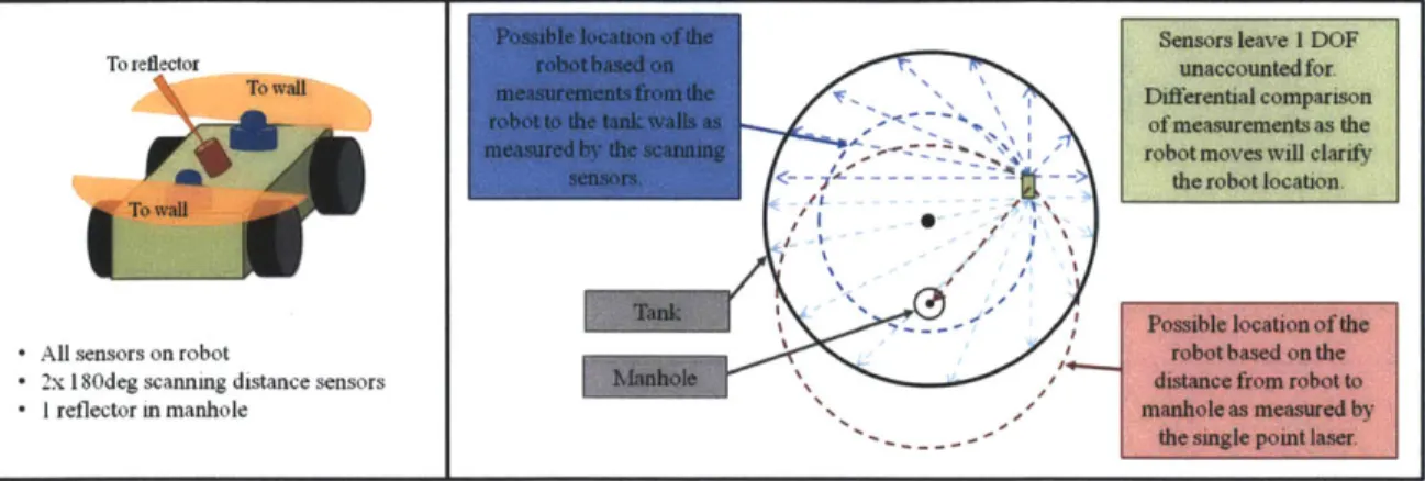
2-2 On Robot Concept 2: A set of scanning distance sensors on the robot in a plane parallel to floor with 1 single point distance sensor measuring to a reflector in the manhole. The large black circle represents the tank walls. The small black circle is the manhole. The black dot is the center of the tank. The green rectangle represents the robot. The dashed arrows represent the measurements taken by the sensors and the dashed line circles show the possible locations of the robot based on the measurements. The circle intersections are the possible locations of the robot. The location is finalized by the measurement to the reflector. 44
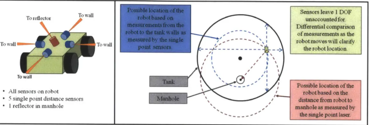
2-3 Concept 3: A set of single point distance sensors on the robot in a plane parallel to floor with 1 single point distance sensor measuring to a reflector in the manhole. The large black circle represents the tank walls. The small black circle is the manhole. The black dot is the center of the tank. The green rectangle represents the robot. The dashed arrows represent the measurements taken by the sensors and the dashed line circles show the possible locations of the robot based on the measurements. The circle intersections are the possible locations of the robot. The location is finalized by the measurement to the reflector. 45
2-4 Concept 4: A separate sensor module consisting of a set of scanning distance sensors dropped into the tank measuring the distance to walls and robot. The large black circle represents the tank walls. The small black circle is the manhole. The black dot is the center of the tank. The green rectangle represents the robot, while the red dot represents the sensor platform. The dashed arrows represent the measurements taken by the sensors. . . . . 46
2-5 Concept 5: A physical tether to the robot from the manhole. The
orientation and the length of the tether determine position. The large black circle represents the tank walls. The small black circle is the manhole. The black dot is the center of the tank. The green rectangle represents the robot. The dashed line circle shows the possible loca-tions of the robot based on the length of the tether. The two angle measurements determine where the robot is on the circle defined by the tether length. ... ... 48
2-6 Concept 6: A local GPS-like system consisting of distance measuring sensors placed on walls by robot as it heads into tank. The large black circle represents the tank walls. The small black circle with a central dot is the manhole. The larger black dot is the center of the tank. The green rectangle represents the robot. The dashed line circles show the possible locations of the robot based on the distance measurements from each sensor. The circles' intersection is the location of the robot. 49
2-7 Concept 7: A local GPS-like system consisting of distance measuring
sensors on a expanding scaffolding hanging from the manhole. The large black circle represents the tank walls. The small black circle with a central dot is the manhole. The larger black dot is the center of the tank. The green rectangle represents the robot. The orange triangle represents the expanding network with sensors on each corner. The dashed line circles show the possible locations of the robot based on the distance measurements from each sensor. The circles' intersection is the location of the robot. . . . . 50
2-8 Concept 8: A sensor module consisting of a single point distance sensor
and two axis angle measurement devices placed in the manhole. The large black circle represents the tank walls. The small black circle is the manhole. The black dot is the center of the tank. The green rectangle represents the robot. The measured distance and the angle of the measurement fully define the location of the robot. Measurements can also be taken to the walls to collect data for a map of the tank. . 51
2-9 Two surveying total robotic systems. Left: Trimble S8 surveying total
station [9]. Right: Leica TPS1200+ surveying total station[10]. ... 54
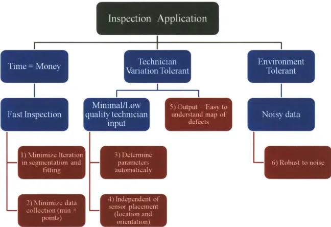
3-1 How the tank inspection application drives the algorithm requirements. The three application needs of minimizing time, being tolerant of tech-nician variation and error and being tolerant of noise induced by the environment drive the six algorithm requirements of minimizing it-eration, minimizing the amount of data, determining the parameters automatically, being sensor location and orientation independent, out-putting an easy to understand tank map and being robust to noise. . 58
3-2 Right capped cylinder with tank and sensor coordinate frames. The cylinder coordinate frame is designated by XYZ where Z is aligned with the center axis of the cylinder. The sensor has two coordinate frames, 6#z and xyz, where z is aligned with the starting direction of the sensor for both. . . . . 61 3-3 Resulting data from different sensor platform orientations upon data
collection startup. Tank rotation is dependent upon sensor starting orientation. . . . . 62
3-4 Alorithm processing flow. Process movement is shown by black ar-rows Note the repeating steps within the data collection process. Data passed from one step to the next is shown by large arrows. . . . . 64
3-5 Possible layouts for neighborhood points collection. a) a checkerboard layout with points evenly distributed along both axes b) a circular
layout with points evenly distributed around the circle perimeter. . . 66
3-6 Standard Deviation in Normal Angle, STD, vs the number of points (N) and characteristic length (L) of a circular point layout and square
checkerboard layout for noise standard deviation of 0.02. The equations for the planar fits are shown in Equ. (3.7) and Equ. (3.8). . . . . 67 3-7 Encoder resolution effect on distance measurement error. The actual
position of the axis can be anywhere within the step size of the encoder resulting in an angular error and mis-measurement of the distance, ee 69 3-8 Simulated average error in cylinder fits vs the neighborhood radius as
a fraction of either the diameter or height, whichever is smallest. This was simulated without noise to isolate the effects due to smoothing. A safe upper limit for neighborhood radius size is approximately 20% of the smaller tank dimension . . . . 70 3-9 Derivation of allowable angular error, 0
e from input allowable accuracy,
3-10 Effect of sensor placement on data collection. As shown in a, c and d,
data points collect around the sensor when a portion of the sensor view is obstructed. The best data is evenly distributed about the cylinder. The best place for the sensor is to be placed in the center of the tank as shown in b. The worst place is in the corner of the tank as shown in a . . . . 73 3-11 Using n, and r, to find commands for sensor platform. a) The
projec-tion of the desired neighborhood circle onto a unit sphere surrounding
the sensor. b)The vectors used to calculate the neighbor locations. . . 74
3-12 Gaussian mapping of an uncapped cylinder (a) and a plane (b) onto
the Gaussian sphere. . . . . 77 3-13 (a) Simulated raw data with arrow indicating floor normal. (b) 3D
Histogram of the Gaussian mapping of a capped cylinder. Note the one point (at the end of the arrow) where the color difference indicates many normals is in line with the expected floor normal . . . . 78
3-14 Deriving bin size from 0
e. Worst case error is from the center of the bin to its corner. Bins are arranged at a unit distance from the center of the sphere, thus the arm length is 1. . . . . 79 3-15 Isolation of the floor, roof and wall data sets. The only points excluded
are those from the corners that are ambiguous as to which group they b elong . . . . 81 3-16 Derivation of 6z and 6r. The tank is tipped by 0. Ad and Az are the
extents of the data in the corresponding direction. . . . . 82 3-17 Cylinder Fitting Steps and Final Completed Fitting. The white stars
are the date points, while the black is the fitted plane/cylinder. In the top row are the floor and roof fits from left to right. The bottom left is the cylinder fit. The bottom right is the trimmed and combined fit. 85
4-1 Raw data, fits and fit accuracies of varying simulated tests. The simu-lated sensor was rotated by 15, 30, 45, 60 and 70 deg with varying tank heights, diameters and manhole locations. The manhole locations are
indicated by the black circle in the raw data image. . . . . 88
4-2 Skewed circle data. The blue line indicates the expected circle, while the black shows the resulting circle fit from the algorithm. The line passing through the points where the two circle intersect is the axis the cylinder is rotated. . . . . 89
4-3 Accuracy versus sensor noise. The desired accuracy for the tests that make up the chart was 0.05m. The accuracy is within tolerance for noise levels up to the desired accuracy and sometimes above. . . . . . 90
4-4 Algorithm segmentation and fitting time as a function of the number of points. It shows an exponential increase. Even above 10000 points, the time to process the data points is only a few seconds . . . . 91
4-5 Prototype Gimbal.Consists of a nested U shaped structure driven by a Maxon EC-Max 40 and RE 50 motor, controlled by Maxon EPOS2 controllers. The rotational sensors are SICK DFS60A 65536 count encoders. The distance sensor is a 17m range SICK DT500. . . . . . 92
4-6 Prototype Tank. Made of a PVC frame covered by stetched fabric. The tank was placed on a rubber floor. . . . . 93
4-7 Test Run Data. a) The raw test run data using the tank and sensor platform described above. b) The same data rotated with the outliers removed and its fit. The roof data is very angled, most likely due to reflection problems between the laser and stretched fabric. . . . . 94
B-1 Main Program Front Panel . . . . 134
B-2 Main Program Block Diagram . . . . 135
B-3 POI Calculation SubVI Connector . . . . 136
B-4 POI Calculation SubVI Block Diagram . . . . 136
B-6 Neighborhood Property Calculations Block Diagram.
B-7 Neighbor Location Calculations SubVI Connector .
B-8 Neighbor Location Calculations Block Diagram . . .
B-9 Radian to Quadrature Count SubVI Connector . . .
B-10 Quadrature Count to Radian SubVI Connector . . .
B-11 Radian to Quadrature Count SubVI Block Diagram B-12 Quadrature Count to Radian SubVI Block Diagram B-13 Motor Movement SubVI Connector . . . . B-14 Motor Movement SubVI Block Diagram . . . .
B-15 Read Distance SubVI Connector . . . . B-16 Read Distance SubVI Block Diagram . . . .
137 . . . . 138 . . . . 138 . . . . 139 . . . . 139 . . . . 139 . . . . 139 . . . . 140 . . . . 140 . . . . 141 . . . . 141
C-1 Clipping process in the z direction. z5 is the 5th percentile of the data.
z9 5 is the 95th percentile of the data. zo and zioo are the modified
extents containing all valid data but excluding outliers. 1 is the actual height of the data. . . . .
C-2 Clipping process in the radial direction. . . . .
143 145
List of Tables
2.1 Sensor Platform Functional Requirements . . . . 33
2.2 Pugh Chart of Sensor Technology Options . . . . 40
2.3 Pew Chart of Sensor Placement Concepts . . . . 53
3.1 Required User Inputs . . . . 68
3.2 Optional or Derived User Inputs . . . . 68
4.1 Estimated Parameters Using Various Numbers of Neighborhoods . . . 94
Chapter 1
Introduction
1.1
Motivation
Inspecting large liquefied petroleum gas (LPG) tanks for defects is difficult, expensive and energy intensive. LPG is stored in steel alloy tanks at approximately -160C. These tanks are periodically inspected for cracks, corrosion and other defects, despite the significant hazards to the inspector [11]. External inspection is not possible for the lowest im of the walls and the floor of the tanks due to structural concrete in these areas. The current inspection process poses serious safety challenges as it involves sending human inspectors into the emptied tanks. The tanks need to be taken out of service and warmed for 10-14 days in order to make them safe for human ingress [12]. The cost of this shutdown is approximately 15 million dollars per day and significant energy is required to warm the tanks up and then cool them back down.
A robotic inspection system will make the inspection of LPG tanks more efficient.
The down time can be shortened because the tank will not need to be as warm for the robot inspector as it needs to be for the human inspector. This reduces inspection cost and there will be less energy used to cool the tank back down to operating temperatures. The inspection process itself can be done more quickly and thoroughly because the robots will move along prescribed paths more accurately than human inspectors. The risk is also diminished because robots are not sensitive to the same hazards as human inspectors.
1.2
Research Focus
The purpose of this research is to develop a robust, efficient, self-contained localization module for use in a robotic liquefied petroleum gas tank inspection system. This module consists of the hardware sensing platform and the corresponding algorithms for mapping the environment. It will be used with a new inspection robot being developed in a joint project between MIT and Qatar University.
The first part of the work is designing a sensor hardware platform. The design process involves determining the best sensing technology, followed by determining the optimal layout of the sensors in the LPG tanks. These choices must take into consideration the environment of the tank as well as the lack of any distinguishing features besides the presence of a manhole in the walls or roof.
The second part of the work focuses on fitting the 3D data from the sensor platform to a capped cylinder. The resulting fit creates a map of the environment to be used in inspection robot path planning and defect localization. The algorithm needs to be robust to noise because the environment and interaction between the sensor and tank walls may result in significant error. It also needs to be faster than current fitting methods to decrease inspection time.
1.3
Background
1.3.1
LPG/LNG
Liquefied Petroleum Gas, or LPG, refers to a class of hydrocarbon fuels composed mostly of propane and butane [13]. LPG is gaseous at atmospheric temperature and pressure, but it can be cooled or compressed into a liquid. LPG is commonly used as fuel in heating, cooking and even vehicles. It is a byproduct of natural gas or crude oil refining so large tanks are often found on-site at petroleum processing plants [13]. These tanks must be periodically inspected for corrosion, cracking and other defects. Figure 1-1 shows a few examples of the large LPG storage tanks.
Figure 1-1: LPG Storage Tanks. (a) Dominion Cove Point LNG facility located in Lusby, Maryland. Photo courtesy of Dominion Corporation [1]. (b) Two LPG storage tanks. Photo courtesy of Lusas Corporation [2]. (c) Row of LPG storage tanks. Photo courtesy of Gauging Systems Inc [3].
- Steel Inner Tank - Pearlite Insulation - Carbon Steel Liner - Concrete Support Wall Primary Steel Bottom
Secondary Bottom Base Insulation Carbon Steel Liner Concrete Base Layer
Figure 1-2: LPG Tank Cross-section. Multilayer construction of steel plating, insu-lation and support walls. Domed carbon steel top has suspended aluminum deck. Concrete base layers and support walls make external inspection impossible.
inspection. LPG tanks are carbon or duplex steel approximately 98m in diameter and 60m tall. The tanks sit on concrete slabs with their walls reinforced by concrete for at least a meter up from the floor. The details of the tank structure are shown in Figure 1-2. External inspection of the floor and walls behind the concrete is impossible, so internal inspection is necessary. The temperature inside is cryogenic even after draining. There is no source of light in the tank and any light source needs to be low power in order to avoid ignition of residual particles. The residual particles also impose limitations on other energy imparting systems, such as EM radiation. The low temperatures, residual flammable particles and lack of light need to be taken into consideration when designing an inspection system.
1.3.2 Conventional Inspection
Conventional inspection is completed by human inspectors inside the tank with spe-cialized equipment. The tank must be drained, warmed to habitable temperatures and cleaned before the inspector is sent in [11]. The inspector collects a sparse amount of data due to the slow speed of human inspection and limited allowable exposure time. After inspection the tank must be cooled to cryogenic temperatures before being put back into service.
Conventional inspection has many negatives including high cost, being hazardous to the inspection staff, and negative environmental impacts. Taking the tanks out of service and warming them to habitable temperatures is very costly, approximately
15 million dollars per day of down time for up to two weeks. In addition to the
high cost of inspection, there are significant safety and health challenges to manned inspection due to the confined space and residual material [12]. Cleaning the tanks for human ingress involves degassing the tank and cleaning sludge from the bottom. The release of gas into the environment and the disposal of sludge is hazardous to the environment. Developing a robotic inspection system that can withstand colder temperatures and does not require complete degassing or cleaning of the tank floor removes the safety and health issues and greatly reduces the environmental impact of tank inspection.
1.3.3
Robotic Inspection
Robotic inspection has the advantages of not exposing human inspectors to the tank environment, reducing the cost and environmental impact and being more effective than human inspection. The temperature of the tank will not need to be raised to as high a temperature because the robot habitable temperature is much lower than human habitable temperature. This will reduce the energy needs and down time resulting in a less expensive inspection. A robot inspection system would not require complete degassing and cleaning, thereby reducing the environmental impact of inspection. The robot can also be designed to clean the tank during the inspection routine much like the Techcorr robot in Figure 1-3 (e). Robot inspection removes the risk to inspectors because they are not needed in the tank. Finally, robotic inspection will result in a complete inspection of the tank because the robot can be exposed to the hazardous environment for longer than a human inspector.
Figure 1-3: Inspection Robots. (a) External crawling inspection robot [4]. (b) Mav-erick, a remote-controlled, submersible robot for inspection of gasoline tanks [5]. (c) Neptune, a fuel storage tank inspection robot [6]. (d) ICM climbing robot with in-stalled NDT sensors [7]. (e) Techcorr cleaning and inspection robot [8].
Current inspection systems are unable to replace human inspectors for the bottom of LPG tanks.. Robotic inspection of storage tanks is not a novel idea. Some current inspection robots are shown in Figure 1-3. Most inspection robots can attach to and inspect the tank externally, such as the robot in Figure 1-3 (a) [14][15]. These robots
can only inspect the walls above the structural concrete with no way to inspect the floor of the tank. There are some robots, such as those depicted in Figure 1-3 (b), (c),
(d) and (e), that can access the floor of tank through internal inspection, but they are
designed for tanks storing other substances [11] [16]. These robots are designed for use in tanks storing products that are in a liquid state and stored at room temperature, namely kerosene, gasoline, jet-fuel, etc. One of the unique challenges of designing an inspection robot for LPG tanks is that the tank is held at cryogenic temperatures. None of the previous designs are applicable to use in this environment, so a system needs to be developed to specifically address LPG tank inspection.
1.3.4
Proposed System Design
Cable
Management
System
Figure 1-4: Proposed Design of Inspection System. Internal mobile inspection robot scans inside surfaces of tank for defects. Localization sensor platform locates and tracks position of inspection robot. Controlling computer is located outside the tank, away from the hazardous environment inside the tank.
The proposed inspection system design consists of a mobile platform, an ingress and egress mechanism, non-destructive testing equipment, an external controlling computer, and a localization system. The layout of these components are shown in Figure 1-4. The NDT equipment will be mounted on the mobile platform that enters the tank via the ingress and egress mechanism. A controlling computer will be located
outside the tank and will communicate with the robot, either through an umbilical cord or a wireless system. Placing the controlling computer outside the tank reduces the explosion risk by keeping the majority of the electronic switching outside the explosive environment. A localization system will be placed in the manhole to create a reference frame from which a map of the tank will be created.
This thesis encompasses the work done on the design of the localization system for the robotic LPG tank inspection system. The first component of the work is the sensor platform design, including the concept definition and hardware selection. The second part of the work consists of the development and first implementation of data collection and tank mapping algorithms. The fitting algorithm detailed in this work is specific to cylindrical tanks with planar caps because it is the most common LPG storage tank shape.
1.4
Prior Art
The two components of the inspection system detailed in this thesis are the design of the localization system hardware and the processing of the collected data into a useful map. This section discusses prior work done on localization systems, followed
by a discussion of the prior work done on fitting a capped cylinder to 3D data.
1.4.1
Localization Method Prior Art
There are four methods of locating a mobile robot discussed here: triangulation, vision, landmark interaction, and dead reckoning. These three methods are the most common means of localizing a robot in its environment. The method of localization and limitations of each of these methods are described below.
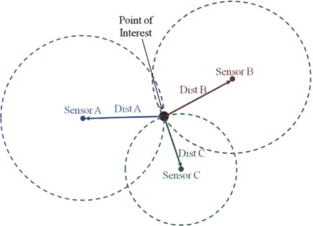
One of the most common methods for locating mobile robots is triangulation. Three or more sensors with known locations send out signals in all directions. The signals are received and returned by transceivers on the robot [11][17]. The distance to the robot from each sensor can be calculated from the time of flight of the sensor signal to and from the robot. The distance from the sensor defines a sphere of possible
Point of ... . .- -- Interest Sensor B Dist SensorA DistA / I st C ---Sensor C A/
Figure 1-5: Triangulation. Distance from sensor creates a sphere(or circle when in
2D) of possible locations of the point of interest. The intersection of the spheres(or
circles) pinpoints the location of the point of interest.
robot locations. The sphere's intersection pinpoints the location of the robot as shown
in Figure 1-5. A method of repeatedly and accurately placing triangulation sensors will need to be developed before triangulation is a feasible option for the inspection
localization system.
A second localization method is to use vision sensors to image the environment [18]. This is most similar to the human method of localization. A robot uses a camera, instead of eyes, to record its surroundings and then extracts details of the environment
to orient itself by. There are two major difficulties with vision localization in an LPG tank. The first difficulty is the lack of guaranteed features in the tank. There may not be any features in the tank that can be extracted from images to orient the robot with. The second difficulty is the lack of light in the tank. There is no light entering the tank, and only a low power light source can be used without risking explosion.
Another method that is similar to a vision based system is a method that uses
landmark sightings [19]. Landmarks are placed at known intervals in the environment.
These landmarks can be visual or can use another technology. They are detected
landmarks. The difficulty with this method is that the landmarks would need to be placed accurately. This limits the transportability of the system in the same way that placing triangulation sensors do.
The above methods are usually combined with dead reckoning
[19].
Dead reckon-ing uses sensors that measure the motion of the robot wheels or tracks. The amount of rotation is directly related to the distance traveled. Errors in the measurement of the distance traveled occur when the wheels or tracks slip. Slipping is more likely to occur on uneven ground, which the tank may have due to uneven build up of partic-ulates. The slipping error keeps dead reckoning from being a stand alone method for localization, but it can provide supplemental information when used in conjunction with another localization method.All of the localization methods listed above have significant difficulties when
ap-plied to an LPG tank inspection system. A method needs to be designed that can work in the LPG tank conditions. The requirements and design of a localization sensor platform that can overcome the difficulties of the environment are described in Chapter 2.
1.4.2
Data Processing Prior Art
Processing environment data involves segmenting it into sections that are then fit to geometric primitives such as planes and circles [20][21]. The edges of the shape are located at the intersection of the geometric primitives. All fitting is done us-ing a batch least squares optimization method. This thesis focuses on developus-ing a new segmentation method that is faster and more robust to noise than the current methods.
There are four categories of segmentation methods: Clustering, Seed and Grow, Edge detection and Hough Transform. In each of these methods, properties of points on the surface of the object of interest are used. Usually these properties are the position and orientation of the surface normal at the point of interest [22]. Each of these methods is described below.
similar properties are grouped together. Points are considered to be part of a cluster when the properties of the point of interest and the properties defining the cluster are within a user defined similarity threshold. When a point does not belong to any of the existing clusters, a new cluster is formed. The comparison process iterates through each point on the surface until all points have been sorted into a cluster. Each point now lies in a cluster and each cluster corresponds to a surface.
Seed and Grow is similar to clustering in that it groups together points with similar properties. The difference is that random seeds are selected and compared to their neighbors instead of to a set of clusters. Neighboring points are compared and collected into a group until the discrepancy between the properties of the current point and its neighbor exceeds a user defined threshold. Once all the neighboring points next to the grown section fall outside of a threshold for similarity, another seed is chosen. The process repeats until all points are inside a group. A final sweep combines homogeneous regions [21] [22].
Edge detection also compares neighboring points, but in this method points defin-ing the edges of the surfaces are collected instead of points within the surfaces. The properties of each point are compared to the properties of all its neighbors. An edge is indicated when discrepancies reach a defined threshold. These edges are collected and used to define the extents of each section [23].
The Hough Transform relies on a voting procedure to find the most common geometric parameters for a given area. Several points are chosen and all possible planes (or whatever shape is of interest) that intersect these points are determined.
A vote is cast for each of the possible solutions. The solution with the most votes is
assumed to be the true fit [24] [25]. Multiple surfaces will result in multiple solutions with a large number of votes. Each point's properties are then compared to the solutions and grouped according to the best fit.
These methods are flexible in the shapes they are able to segment and fit, but there is room for improvement when segmenting inspection environment data. These methods are flexible because they assume nothing about the environment from which the data is being extracted. No external information is needed and the solution
is unconstrained. This flexibility comes at the expense of computation power and processing time. All the methods mentioned above require iteration to converge on a solution. The computation expense and processing time can become significant when the size of the data point cloud is large [26]. Improvement on processing time and computation needs can be achieved by integrating some knowledge of the solution into the algorithm. Fortunately, the general shape of the inspection environment is known in the case of inspection robots. The shape knowledge can be used to remove iteration which is the major contributor to the time and computational expense. The knowledge can also be used to reject noise errors in the data, making the fit more robust to noisy data than the methods mentioned above.
1.5
Scope
This thesis describes the design of a localization sensor platform and corresponding algorithms for an LPG tank inspection localization system. Chapter 2 discusses the qualitative design process and selection of technologies for the sensing platform. Chapter 3 details the data collection and mapping algorithm. Chapter 4 describes simulated and real world testing of the algorithm and hardware design. Chapter 5 summarizes the work completed on the localization system and provides a discussion of future work that could be done to improve the system.
Chapter 2
Sensor Platform Design
The first step in designing a robot localization system is to determine the best hardware design given the contraints imposed by the environment. This chapter describes the qualitative design process used to design the localization platform for a robotic LPG tank inspection system. It begins with a discussion of the system requirements followed by an evaluation of the available sensing technologies. Eight sensor layouts are evaluated and the final design concept is discussed in detail.
2.1
Sensor Platform Requirements
The requirements for a localization sensor platform in an LPG tank are driven by three factors: the environment in which the platform will be operating, the need for the system to be portable between tanks, and the funding limitations. The requirements are listed in Table 2.1.
Table 2.1: Sensor Property
Sensing Distance Range Operating Temperature
Size (width x length) Energy Released Tank Independent Commercial Availability
Cost
Platform Functional Requirements Required Desired 0 to 98 0 to 150 -100 to 50 -100 to 50 <0.5 x 0.7 0.1 x 0.1 <0.48 <0.25 Yes Yes
Available Readily Available <20,000 <10,000 Units m C m mJ $
The tank environment influences the sensing distance range, the operating tem-perature, the size and the energy released requirements of the sensing platform.The sensing distance range is determined by the size of the tank. The diameter of the tank is 98 m so the sensor's minimum required range is 0 to 98 m with a desired range up to 115 m, the diagonal distance across the tank. The system must be small enough to fit through the 0.5 m diameter manhole. The environment in the tank can be down to -100 C, while the temperature outside the tank can reach up to 50 C. The sensor system may need to operate in both environments, so the required and desired operating temperature ranges are -100 to 50 C. The tank is also dark so any sensor system needs to be able to operate in low light or use a low power light source. The sensors must also emit only a low amount of power due to the explosive nature of the fumes in the the air. The minimum ignition energy for propane in air is 0.25-0.48 mJ
[27]. Any sensor must be emitting lower than 0.48 mJ energy, preferably less than 0.25 mJ. A final but unlisted requirement driven by the metal tank wall is that only
systems sending signals from within the tank are acceptable. The metal tank acts as a Faraday cage, thus signals from outside the tank are unreliable.
The second driving factor on the requirements is the need for the system to be portable which influences the size and tank independent requirements. The system needs to be small enough to be carried by a single technician so that it can be easily moved between tanks. The system also needs to be independent of which tank in which it is being used, thus nothing can be permanently installed in the tank. Finally the system needs to be tolerant of installation variations.
The final driving factors are the logistical and financial considerations due to funding limitations. The time limitation of the funding source does not allow for the design and testing of new technology. Any technology used in the platform needs to be composed of off-the-shelf components. In addition, the cost of the system should be reasonable. The cost limitations of $20,000 and $10,000 are order of magnitude estimates based on the cost of the robot and the amount of the project funding. These limitations only eliminate expensive technologies that could dominate the system cost.
2.2
Distance Sensing Technologies
A range of sensing technologies were examined before the optimal technology was
identified. The first technology examined was a vision sensor system as it mimics how the human inspectors would navigate around the tank. A local GPS system was considered, followed by Acoustics, otherwise referred to as SONAR. Finally, two types of EM sensors were considered: RADAR and LIDAR.
2.2.1 Vision Sensors
A vision system was initially considered but immediately discarded. There are three
issues that made the abandonment of vision sensors reasonable. The first is the lack of available light in the tank. Any vision sensor would have to be able to take images with very little to no light and the addition of a light source is almost impossible due to the risk of explosion. The second issue is the lack of distinguishing features in the tank. Even if images were able to be recorded, there are no features that could be used as references for locating the robot. The third reason for discarding the vision system is that it would require a high bandwidth connection to the controlling computer. Communication between the robot and the controlling computer is going to be limited so a low bandwidth sensor is preferred.
2.2.2 GPS
Localization via GPS was also immediately discarded. GPS, Global Positioning Sys-tems, operate by receiving signals from satellites. The location of the sensor is found relative to the satellites' known locations using triangulation [28]. There are two problems with this technology when being applied to localization within the tank. The first is that even high resolution GPS is only accurate to within a few meters
[29]. It is desirable to know the robot localization within a few centimeters which is
orders of magnitude better resolution than the GPS can supply. The second problem is that the metal tank creates a Faraday cage that will prevent clean signal reception from external sensors [30].
2.2.3
Acoustic
A third technology considered for the distance sensor was acoustic sensing, otherwise
known as sound navigation and ranging or SONAR. In these sensors a series of acous-tic waves, usually in the ultrasonic range, are generated by a transducer and travel through the environment. When the waves hit an object, they are reflected back to-ward the receiver. The distance of the object from the sensor is directly proportional to the time from transmission to detection and the properties of the medium through which the wave is traveling
[31].
The sound waves can be concentrated in a beam to generate directional information in addition to the distance measurement.The maximum distance and measurement accuracy of sonar heavily depends on three factors: the operating frequency, the acoustic impedance of the medium and the acoustic impedance of sensors. High frequency waves result in better accuracy, but are attenuated more quickly than low frequency waves. Low impedance environments, such as air, need larger amplitude waves to achieve enough acoustic power to travel. To get these large amplitudes low frequencies would be needed. A rule of thumb is that it is only possible to image a feature that is larger than the wavelength of the signal. The application needs good resolution so it would need a high frequency signal, but the high frequency signal would be too attenuated at 98 m to be able to return to the transducer resulting in conflicting signal needs for the desired rsolution and sensing range. Conduction between the transducer and the environment also impact the measurement. Conduction is best when the impedance of the sensor matches that of the environment. The most common transducer is made of piezoelectric material which has an impedance of 35 MPas/m [32]. The impedance of air is approximately 420 Pas/m [33]'. The piezoelectric transducer is mismatched to air by about 105. This large impedance mismatch indicates that the sensor will not generate good signals in air. The conflicting signal needs for the resolution and range combine with the mismatch in impedance make conventional transducers poor sensors for an LPG tank localization system.
distances needed to sense the tank. Acoustic sensors for use in air have a max range of a few meters due to the mismatched impedances. A new transducer would need to be developed using a material with the same impedance as air to acheive the desired accuracy and the necessary range. As mentioned in the requirements section, the development of a new sensor is out of the scope of the project, thus SONAR sensors are not a good option for the main distance sensor.
2.2.4
Electromagnetic Sensors
The last set of technologies that were explored were electromagnetic sensors. Elec-tromagnetic distance sensors use a process similar to that of acoustic sensing where a wave pulse is emitted into the environment and the distance to the object it hits can be calculated from the time to receive the reflected returning signal. The main dif-ference is the type of wave used. Conventional radio detection and ranging, RADAR, uses electromagnetic waves in the radio frequency range where the wavelength ranges from 1 cm to 100 m [34]. Millimeter wave radar uses waves with 1 mm to 7.5 mm wavelength [34]. LIDAR, light detection and ranging, uses visible or infrared waves, generally with 600-1000 nm wavelengths [34].
Conventional Radar
Conventional RADAR is a common technology in marine and air vehicle detection, but has significant issues that limit its applicability as an LPG localization sensor. Radar waves are reflected when there is a large change in dialectic or diamagnetic constants, which is the case for metal vehicles in the air or water [34]. For the tank inspection application, the boost in signal for metal in air is a hindrance because the large metallic wall will result in a strong signal that may wash out any signal returned
by the small robot. Another reason that radar is used in vehicle detection is that
the radar sensing range is large due to its long wavelength. While long wavelengths are a benefit in long range detecting, they are problematic in terms of accuracy. It is generally considered to only be possible to image a feature about the same size or
larger than the wavelength [34]. This means that most traditional radar sets would not be able to sense our robot due to its small size. The minimum range for sensing is also dependent on the wavelength, with longer wavelengths unable to measure close distances. For instance, marine RADAR typically has a minimum sensing distance of 20 m, much larger than the required minimum required by the LPG system [28]. Marine radar was particularly explored because it has the smallest traditional radar packages. Even so, the size of the marine radar sets were just slightly too large for the application. Traditional radar is not a good technology for this application due to its inability to meet the minimum sensing distance, resolution and size requirements.
MM Wave Radar
Millimeter wave radar is a promising modification of conventional radar for sensing distances in a range appropriate for a tank inspection localization system, but it is still too young of a technology to apply to this project. MM wave radar operates using the same principles as conventional radar, but it uses millimeter length wavelengths. It does not suffer from the same limitations of traditional radar systems, but has a shorter maximum sensing distance. Its smaller wavelength reduces the minimum sensing distance to 0.6 m and increases the resolution to 5 mm [35]. This is at the expense of the maximum sensing range, now 500 m, which is still over the maximum range the localization system would need. Due to its relatively new nature, it is not widely in use and not readily available. The majority of users create their own system, and the commercially available versions are expensive.
Lidar
The final potential technology considered was LIDAR, light detection and ranging. The wavelength used for LIDAR is in the visible or infrared region of the electromag-netic spectrum. The short wavelength limits the maximum sensing distance to lower than 300 m, but it has a shorter minimum sensing distance of 0.2 m, and a better resolution of 1 mm [36]. LIDAR is commonly used as a distance measuring technology in many fields such as robotics, manufacturing, mapping, and construction so there
are many commercially available laser rangefinders.
Commercial LIDAR systems measure distance using one of two methods: phase shift or time-of-flight. Time-of-flight, TOF, uses the same process described in the RADAR section except in this case the relationship is related to the speed of light instead of the speed of sound. The equation governing the relationship between the time of flight, tf light, and the speed of light c are shown in Equ. (2.1) [37].
dist= c * tflight (2.1)
In phase shift measurements, the sensor emits a wave of known frequency which bounces off the object to be measured. The phase of the returned wave is measured
by the sensor. The difference in phase, the phase shift, is related to the time of flight
in Equ. (2.2) [37].
0 = 2 (tflight) (f (2.2)
where
f
is the frequency of the wave. The distance point to the of interest can be found by solving Equ. (2.2) for tflight and using that value in Equ. (2.1). Aliasing occurs if the distance to be measured is longer than the wavelength of the signal. Multiple waves of varying frequency can be used to remove the aliasing effect[37].
Both TOF and phase shift techniques can be used to achieve the requirements listed above so other considerations were used to determine which technology is the better option. TOF uses laser pulses instead of continuous laser beams to measure distance. Although the pulses are powerful enough to measure large distances, they do not accumulate significant energy due to their short duration. This is important to the LPG device because there is a risk of igniting the fumes remaining in the tank if too much energy accumulates. For example, the Acuity AR3000 is a 193 nJ laser pulsed at 2 khz for 6 ns when using time-of-flight for measuring distances [36]. This is orders of magnitude smaller than the minimum ignition energy of propane in air of 0.25-0.48 mJ [27]. TOF sensors are also better able to measure wet surfaces, which may be present in the tank, and TOF is more capable of measuring off oblique surfaces thus allowing for more freedom in sensor placement [37]. Time-of-flight has multiple
advantages over phase shift sensing making it a better option for this application.
2.2.5
Sensor Technology Conclusion
Of the three technologies available for distance measuring, LIDAR is the best option
for this application. Vision does not work because of the lack of light and bandwidth needs. GPS is not acceptable because of the Faraday cage effect of the tank and its large resolution. Sonar does not work because there is no commercially available sensor that can achieve the required resolution over the required sensing range. The three EM sensing technologies are compared with each other with regards to each design requirement in the un-weighted Pugh chart, Table 2.2. Conventional radar is eliminated because it does not meet the needed sensing range and does not fit the size requirement. Millimeter wave radar meets the technical requirements, but it is not readily commercially available within an acceptable price range. Table 2.2 clearly shows LIDAR as the best option for this application.
Table 2.2: Pugh Chart of Sensor Technology Options
Technology Sensing Operating Size Energy Commercial Cost Total
Range Temp Released Availability
Acoustic -1 -1 0 0 -1 -1 -4 Radar 0 -1 -1 -1 -1 1 -3
Lidar 1 -1 0 -1 0 0 -1
LIDAR meets all the sensing technology requirements except for the operating temperature requirement of -100 to 50C. None of the sensors were able to meet this requirement. Electronic component operating temperatures are only rated down to -40 C so no sensor manufacturer will quote a lower operating temperature for any sensing technology. The temperature requirement needs to be removed due to the inability of any sensor to meet it. The temperature problem will have to be accounted for in the design of the sensing platform with some form of heating and insulation.
2.3
Sensor Layout
Several factors need to be considered when determining the optimal way to layout the sensor or sensors. The first two consideration are the cost and accuracy. Multiple or expensive sensors increase the cost of the system, but may increase the accuracy. The trade-off between these two factors needs to be considered for each design. The third consideration is the complexity of the design in regards to communication and fabrication. A good design will minimize the complexity because it will reduce con-struction costs and often is more robust. The last consideration is the flexibility of the design. It would be preferable if the system that locates the position of the robot in the tank can also map the environment in order to make a map of the tank extents
and the defect locations.
LIDAR sensors can be bought in two forms: single point sensors and scanning sensors. A single point sensor measures the distance to one point in the direction it is facing. The advantage of this type of sensor is that the operating computer will know the direction the laser is pointing at all times. The disadvantage is that to take measurements in more than one direction, a platform will have to be built with actuation in all directions of interest. A scanning sensor already has one degree of rotation actuated. It is usually made from a single point sensor reflected off of a rotating angled mirror. The advantage of this type of sensor is that it is already actuated about one axis so to take measurements in space a platform will only need to be actuated about one more axis. The first disadvantage is that scanning sensors usually cannot rotate a full 360 degrees so multiple sensors would be need to be used. The second disadvantage is that it may be difficult to back out and control the instantaneous direction from the sensor. The scanning sensors are meant to create a horizontal slice of the environment, not point at a single entity. This would limit the flexibility of the sensor platform as it would not be able to track the robot.
There are eight concepts discussed in the following sections. They can be broken into two categories: those with the main sensor(s) on the robot and those with the main sensor(s) located elsewhere. The location, number and type of sensors depend
on the concept. These details and a discussion of the advantages and disadvantages of each design are discussed in the following sections. At the end of the chapter the concepts are compared and the final design is chosen.
2.3.1
On Robot
The advantages of a design where the main set of sensors are on the robot include a decreased chance of communication problems and less of an issue with noise. A physical communication connection between the sensors and the robots can be used when the sensors are located on the robot. The physical connection has a lower probability of encountering communication problems than the wireless system that will need to be used by sensors not located on the robot. The on robot sensors will be located in the same location as the robot, so there is no chance of losing the robot in the measurement noise; the noise just decreases the accuracy of the measurements. The disadvantages of an on robot sensor system include complexity of localizing with no unique environment features and the placement of the sensors within the hazardous environment. A sensing system contained entirely on the robot will need a reference feature to complete its orientation of the robot. The lack of unique environ-ment features will require the placeenviron-ment of an external reference item in addition to the sensors on the robot. The second disadvantage is that all the sensing components will be thoroughly inside the corrosive and thermally challenging environment. Addi-tional advantages and disadvantages depend on the specific setup and are discussed in the concept description.
Concept 1: On Robot Idea #1
The first on robot concept consists of several scanning LIDAR sensors placed on the robot with a pylon dropped in from the manhole as shown in Figure 2-1. At least two scanning sensors will be needed to see a full 360 degrees around the robot. These sensors will map a horizontal plane of the tank walls and pylon in relation to the robot. The radial position of the robot can be found from the distances to the walls

![Figure 1-3: Inspection Robots. (a) External crawling inspection robot [4]. (b) Mav- Mav-erick, a remote-controlled, submersible robot for inspection of gasoline tanks [5]](https://thumb-eu.123doks.com/thumbv2/123doknet/14732873.573440/25.918.192.712.556.828/inspection-external-crawling-inspection-controlled-submersible-inspection-gasoline.webp)

![Figure 2-9: Two surveying total robotic systems. Left: Trimble S8 surveying total station [9]](https://thumb-eu.123doks.com/thumbv2/123doknet/14732873.573440/54.918.207.701.523.894/figure-surveying-total-robotic-systems-trimble-surveying-station.webp)