DETECTION OF OPEN FRACTURES WITH VERTICAL SEISMIC PROFILING
by
1r.B.Beydoun, C.H. Cheng and M.N. ToksOz EarthResources Laboratory
Department of Earth, Atmospheric and Planetary Sciences Massachusetts Institute of Technology
Cambridge,lolA02139.
ABSTRACT
In Vertical Seismic Profiling surveys tube waves are generated by compressional waves impinging on subsurface fractures or permeable zones. The problem of generation of these waves by a non-normal incident P wave for an inclined borehole intersecting a tilted parallel wall fracture is formulated theoretically. The amplitude of tube waves depends on the permeability. the length of the fracture, and on the frequency. The relative effects of these parameters are studied individually. The problem is also formulated for a thin oblate ellipsoidal (penny-shaped) fracture. The results for the two fracture models are compared and contrasted. Field data from Tyngsboro, Massachusetts are shown for open fractures in granite. From tube wave amplitudes normalized to P wave amplitudes, calculated permeabilities are on the order of one hundred millidarcys.
NOMENCLATURE a2 c d
I
g 4(z), lii(z) k KK"
L(t) Lo L m nK IJ.-1')'-1, pressure ditrusivity in fracture
tube wave phase velocity effective length of fracture P wave or tube wave frequency gravitational acceleration constant modified Bessel function of the i-th order r.;1c, tube wave vertical wavenumber fracture permeability (1 darcy= 10-12m2) fracture hydraulic conductivity (10-3 oml sec) fracture width
static fracture width
k (l-c2I ex2)l!, tube wave radial wavenumber
from P wave contribution
k (1-c21(2)l!, tube wave radial wavenumber from S wave contribution
k (1-c2I exJ)l!, tUbe wave radial wavenumber from fiuid P wave contribution
unit vector normal to the fracture walls
generated tube wave pressure amplitude in borehole fiuid in the vicinity of the fracture
262 P(z,t) Po q(z,t) Q(t) r R S T u Beydoun etaL
P wave arrivaL in the vicinity of the fracture tluid pressure distribution in the fracture
equilibrium borehole pressure at fracture depth rate of tluid tlow in the fracture
pressure source function (inhomogeneous term) in PDE (A.2) ellipsoidal fracture radius
borehole radius
axis running along the center of the fracture, oriented away from the borehole
lit. P wave or tube wave period
displacement amplitude along iG in the formation
of the first P wave arrival, in the vicinity of the fracture generated tube'wave vertical displacement amplitude along Zb in the formation, in the vicinity of the fracture
two-dimensional volume of tluid ejected by the fracture in T12
three-dimensional extrapolation of V2D
total volume of tluid ~ectedby the ellipsoidal fracture unit vector oriented Z x
s
unit vector along the borehole axis oriented downwards vertical unit vector oriented downwards
compressional (P) wave velocity of the formation compressional (P) wave velocity of the tluid shear (S) wave velocity of the formation tluid compressibility
Lo/2r, aspect ratio of ellipsoidal fracture
2<"01Lo, maximum volumetric strain (or dilatation) of ellipsoidal fracture
tube wave volumetric strain in the tluid maximum strain vector of the fracture maximum strain vector of incidentP wave maximum normal fracture displacement
cos-l(iG .it), angle between P wavenumber and fracture normal P wavenumber unit vector
dynamic tluid viscosity formation density tluid density
Poisson's ratio of the formation
cos-I(it ' Zb), angle between borehole axis and fracture normal tube wave potential in the borehole tluid
geometrical factor
2rr! ' P wave or tube wave anguiar frequency
INTRODUCTION
(
(
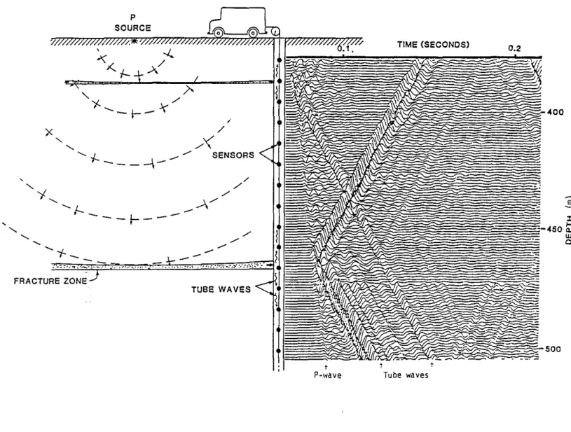
Vertical Seismic Profiling (VSP) surveys have become a very valuable diagnostic tool in the evaluation of the formation properties surrounding the borehole. In tleld experiments with compressional wave VSPs, Huang and Hunter (198la,b) had observed that tube waves are generated at fractures intersecting the borehole. In a similar set of experiments in Tyngsboro and in Hamilton, Massachusetts, we have observed the same phenomena. Examples of tube waves originating at fractures and propagating up and down the borehole
from the data collected at Tyngsboro and Hamilton are shown in a VSP section in Figures 1. and 2. The widely accepted mechanism for the generation of tube waves is that the incident P waves compress the fracture and inject a fluid pulse into the borehole. Figure 3 schematically illustrates this efficient mechanism for the generation of tUbe waves.
The fluid pulse mechanism for the generation of tube waves has been formulated mathematically by Beydoun et al. (1983). The geometrical model used in that study is that of a parallel-walled open fracture intersecting a borehole. A compressional plane wave impinges on the fracture. First, the volume of fluid ejected from the fracture into the borehole is calculated. Then, the tube wave amplitudes generated in the borehole fluid and in the formation are evaluated. Using this model. the in situ fracture permeability can then be estimated from the ratio of the tube wave amplitude to the P wave amplitude measured in the formation or in the fluid. The model used in Beydoun et al. (1983) assumed a vertical borehole, a horizontal fracture perpendicular to the borehole, and a vertical incident P wave normal to the fracture. In this paper we have extend this model to include random orientations of the borehole, fracture and the incident P wave. In addition, we have examined a fracture model based on a thin ellipsoidal (penny-shaped) crack. We will compare the theoretical predictions of the two models and the strengths and weaknesses of each. Finally, we will apply our parallel wall fracture model to the data from Tyngsboro.
THE PARALI..EL WALL FRACTURE MODEL
The theory for the parallel wall fracture model has been discussed in some detail in Beydoun et al. (1983) for the vertical borehole, horizontal fracture and vertical incident P wave. In the following section, we will present the corresponding theory for the angle dependent model. The development is closely parallel to the original model. and we are presenting here the essential results that are different from the previous model. The reader is referred to Beydoun et al. (1983) for the more basic details.
Theory of FluidFlow in the Fracture
Consider a parallel-walled, fluid-fllled open fracture imbedded in a homogeneous isotropis.. elastic medium. The fracture is intersected by an uncased borehole. Let Z be the vertical unit vector, let Zb be the unit vector in the direction of the borehole axis, let fi. be the unit vector normal the the fracture wall, and let i1 be the axis normal to fi. (parallel to the fracture walls and oriented away from the borehole) situated at the center of the fracture. These vectors and their origins are shown in Figure 4. The fluid in the fracture is in equilibrium with the fluld in the borehole. A plane P wave with wavenumber unit vector 1Cimpinges on the fracture. For very small strains, the fracture width is assumed to oscillate about the static shape La as
L(t) =La - (a cos(CJt)
where 2(0 is the maximum normal fracture displacement.
264 Beydoun etal.
(
To simplify the calculations of the fluid injection from the fracture into the borehole, the following assumptions are made: (1) ~o«Lo , (2) one-dimensional linear laminar regime of flow occurs within the fracture (Stokes' law satisfied) , (3) the fluid compressibility is small, (4) the fluid injected into the borehole from the fracture does not significantly perturb the borehole pressure Po at the fracture location and the fracture pressure is equal to Po when the fracture velocity is zero, (5) low frequency approximation with frequency dependence (aT»R,L), (6) the fracture intrinsic permeability, K, does not vary with time, (7) the fracture inclination with respect to the borehole axis 'I' = cOS-I(Zb'n) is small, and (8) if u is the maximum amplitude of the P wave particle displacement (along iC) in the vicinity of the fracture and". = cos-l(iC'n) the angle between the incident wave and the normal to the fracture, then for a thin fracture with large surface area and small flUid compressibility,
~o '" u cos"'.
The two-dimensional problem, where the fracture is infinitely long in the Y direction, will be solved flrst. The fluid flow rate in the presence of a pressure gradient ap (s ,t)/as is related to the fracture width L(t), the flUid viscosity I.J. and density P!., and the fracture intrinsic permeability K by Darcy's law (With Assumption (2), see for example De Wiest, 1969)
( ( q(s t)
= _
.Ii'L(t) , I.J. ap(s,t) as (2) (The elevation gradient term(PI 9 az/ as) is not present because the fracture is plane and point-symmetric with respect to the zb origin.
The fracture movement being T-periodic and T/2 symmetric, we shall investigate the fracture dynamics in a time interval of T/2 (from t=O to t=T/2). The volume of fluid ejected from the fracture into the borehole (fracture closure) during the one-half cycle of the incident wave is (see AppendiX A) ( ( (3) where T/2
F(GJ,~o/Lo) '" 2GJ
J
(T/2-t)l! sin(GJt) dt for ~o«Lo.o
An effective length of the fracture, d, can be defined as the radial distance (along s) from the borehole wall to a point at which the pressure gradient falls to about ten percent the pressure gradient at the borehole wall over a time interval of T/2. The effective fracture length is given by the expression
d(K)
=
[2:/f
This can be verified by substituting Eq. (4) in Eq. (A.4) in Appendix A.
The volume used to derive Eq. (3) is two dimensional. The actual fracture geometry involves a three-dimensional configuration which can be approximated by extrapolation of the two-dimensional solution, assuming the geometry is axisymmetric with respect to the it axis. This geometrical extrapolation is based on the steady state solution, and is assumed to be independent of the small fluid compressibility and of the low frequency of excitation.
Use of Navier-Stokes equation in cylindrical coordinates and the continuity equation (Landau and Lifchitz, 1971) with the assumptions (1), (2) and (5) indicate that the permeability of two-disc radial fluid flow is the same as the permeability of two parallel planes fluid flow. Comparing the steady state solutions for the 2D and 3D problems, the respectively flow rates can be related as follows:
(5) where
The X component is defined as the geometrical factor; cf. is the etl'ective fracture length defined previously in Eq. (4) and R is the borehole radius. For any given time interval the equation relating the two- and three-dimensional volumes is similar to Eq. (5), and in particular tor a time interval of T/2
V(K)
=
2 rr R X(K) V2D(K) (6)where V is the volume ejected from the circular fracture into the borehole during a time interval of T/2.
TubeWave Generation
Tube waves are low frequency Stoneley waves. These gUided waves reach their largest amplitudes at the solid-fluid boundary and decay approximately exponentially away from it. The fluid pulse V forced from the fracture into the borehole by an incident compressional wave generates tube waves which propagate up and down the borehole.
To determine the relationship between the ejected fluid volume and the tube waves generated, the tube wave volumetric strain (or dilatation) in the fluid (
t})
is used. Further, the tube wave and the P wave are assumed to have the same frequency. The integrated tube wave volumetric strain in the borehole fluid (at 2b=0) in the time period T/2 can be equated to the fluidvolume injected into the borehole, -V(K), over the same time period. The minus sign is necessary since the borehole system is ditl'erent from the fracture system: the algebraic volume ejected from the fracture is a negative volume for the fracture but a positive volume for the borehole. In aXisymmetric cylindrical coordinates this volume is expressed as
266 Beydoun et al.
T/2 R
- V(K)
=
2 11" CJ J
6J(r,Zb=O,t) rdr dta a (7)
(
The volumetric strain and amplitude of the tube wave can be determined using the seismic potential for the tube wave (see Appendix B). The amplitudes of the up and down going tube waves will be the same because of symmetry.
The fracture permeability can be evaluated by considering the inverse problem. The in situ fracture permeability can be determined from the tube wave amplitude normalized to the direct P wave amplitude in the fluid (pressure ratio) or in the formation (displacement ratio). The P wave pressure in the borehole fluid can be written in terms of the displacement in the formation (White, 1965) with assumptions (5) and (8)
(
(8)
where rp - '13
=
cos-l(iC .Zb) (oriented angles, see Figure 4.) is the angle between the P wavenumber vector and the borehole axis.Using Eq. (B.2) to (B.8), the ratios of fracture induced tube wave amplitudes to incident P wave amplitudes can be determined. The pressure ratio in the borehole (measured by a hydrophone) is
(
T a r.J(f2 cos'l3(l - (e cos(9'-.,9.)10.)2] Io(nR)
p Ip
=
C .{'A cos(9'-.,9.)e 20. (1 - 2({3 cos(9'-.,9.)1 a)2] where C=C(K) is given inequation (B.8).
(9)
The component along Zb of the displacement ratio at the wall of the borehole (measured by an anchored borehole geophone) is
u!1 (ucos(rp-.,9.))
=
[kKo(lR) + mGKo(mR)]A cos'l3l ({'ocos(rp-.,9.)). (10)The factor A is related to C by Eq. (B.5), and C is related to the fracture flow via Eq. (B.6). Eq. (9) or (10) can be solved to determine the fracture permeability K. Normally, given the formation and fluid properties, displacement or pressure ratios can be determined as a function of frequency With permeability, K, as a parameter. These values can then be compared with observations to determine K.
A simple relation exists between the fracture intrinsic permeability K and the fracture hydraulic conductivity (or coefficient of permeability)K;,
K;,=Kp/glfJ-. (11)
The Sl units of K are m2, and the common unit is the darcy (1 d
=
10-12 m2 ).The Sl units of K;, are ml sec, and the common unit is 10-3 eml sec, which is sometimes called the darcy: to avoid any confusion this nomenclature shall not
be used. However ifthe fluid is water a simple approximate relation exists: 1darcy '" 10-s cml sec,
ELLIPTICAL FRACTURE MODEL
In order to study the model dependence of our results, we need to study different models of fractures. One such model is the elliptic or penny-shaped crack model of the fracture. In this model, the fracture is assumed to be circular, with the fracture height very much smaller than the fracture radius. We also assume that the borehole is located at the center of the fracture, that its radius is small compared to the fracture radius and that it acts as an infinite drain for the fluid ejected from the fracture. In that sense, the fracture can be treated to be under the "drained" condition. Other assumptions are: the wavelength of the incident wave is much longer than the size of the fracture; the frequency of excitation is low enough for complete drainage from the fracture during any stress cycle; and the incident strain is small enough that the fracture is never completely closed.
Under these conditions, the volumetric strain of the fracture is related to the applied strain using the theory of Eshelby (1957). The volumetric strain of the fracture can then be related to the volume of fluid ejected and compared with that obtained using the previous model. The applied strain can be related to the incident displacement. In this way we can relate the incident P wave displacement to the volume of fluid ejected from the fracture into the borehole in a manner similar to that given in Eq. (6).
Theory
Without loss of generality, we can assume the fracture to be horizontal and the borehole to be vertical. An incident P wave impinges on the fracture at an angle" with the normal to the fracture. Using the same coordinate system as in Figure 4., the maximum dilatational strains of the incident P wave are deflned as
e:"
ande:..
If the boundary conditions are written in terms of maximum stresses, we can infer the maximum strains from the constitutive relation of the medium. The incident strain vector (com;osed of the three maximum dilatational components of the strain tensor),e ,
can be related to the strain vector of the fracture,e,
by the matrix equation (Eshelby, 195?; Anderson et al., 1974; Cheng, 1978):(12)
(13) where A is the strain enhancement factor (Korringa et al., 1979). For low aspect ratio (thin) fractures, results show that only
e:"
is important in the calculation of the volumetric strain of the fracture. The maximum volumetric strain ti of the fracture is given by:A __ 4(1 - cr)2
'" ~-=:!-.,...e:z,
1\"<i(1 - 2cr)
where cr is Poisson's ratio of the formation and 6 is the aspect ratio of the fracture (width divided by diameter). From the notations of the parallel wall modeL we have 6
=
Lo/2r and ti=
2101 La. Therefore, the elasticity effects of the medium, ignored in the parallel wall modeL can be taken into account since268 Beydoun etaI.
(
equation (13) links
to
to the boundary conditions in the elastic medium. In the "drained" case under consideration, the volume of fluid ejected can be assumed to be the volumetric strain of the fracture multiplied by the (negative) fracture volume. The volume of an ellipsoidal fracture with radiusr and aspect ratio .5 is 4rr.5r s/3. Thus. the volume ejected into the borehole upon an incident P wave at an angle'" with the normal to the fracture is given by:v.
• = -!.rrr
3 2 ;'0 (14) (
Identifying this volume,
v,.
with the volume V given by equation (6), an expression for the ellipsoidal fracture radius.r. is found:r
=
[;:raf
Note that-Vis a positive quantity (see Eq. 3).
ComparisonwithParallelWallYodel
(15)
(
(
The parameters of comparison are the effective fracture distance, d, versus the ellipsoidal fracture radius. r. The variables considered are the frequency and the fracture permeability. The other physical parameters are kept constant and their values are shown in Table 1. Results are shown in the table below: ( d(m) r(m) f=150 Hz, K=10 d 0.52 0.41 f=100 Hz. K=10 d 0.63 0.48 f= 50 Hz, K=10 d 0.89 0.64 ( f=150 Hz, K= 1 d 0.16 0.18 f=lOO Hz, K= 1 d 0.20 0.21 f= 50 Hz. K= 1 d 0.28 0.29
These results compare favorablyin the sense that they are of the same order of magnitude, considering that the two models presented in this paper are based on totally different approaches. The effective fracture length is comparable to the radius of the ellipsoidal fracture.
There is no dependence on formation properties in the parallel wall model. The main interest was, that assuming the displacement field in the vicinity of the fracture, to calculate the maximum volume of fluid ejected by the fracture, the flUid properties being taken into account. Formation properties can be apprOXimately incorporated by specifying the boundary conditions of the incident field and using Eq. (13).
There is no dependence on the fluid properties in the ellipsoidal crack model. This is because we have used the "drained" assumption. FlUid properties, both elastic and viscous, can be incorporated into the ellipsoidal
crack model (Johnston at a.l., 1979). Furthermore, the borehole radius effect is not present in the formulation since we have assumed the borehole radius to be small compared to r. However, when the borehole radius is decreased by a factor of 10 (from O.lm to O.Olm), the fracture radius calculated using Eq. (15) is decreased by approximately 30 percent. Therefore, the borehole effect does not significantly change the results. Frequency dependence, as used in the parallel wall fracture model, can also be introduced into the ellipsoidal model, provided the long wavelength assumption still holds (Kuster and Toksoz, 1974).
It is clear that for both models, given the observed P wave to tube wave pressure ratio, one can obtain only one parameter for the fracture. In the case of the parallel wall fracture model, the parameter is the width of the fracture, and by inference, the in situ fracture permeability. On the other hand, in the case of the ellipsoidal fracture model, the parameter one can obtain is the radius of the fracture. Comparison of the two models brings additional information. The two main consequences of this comparison are : the parallel wall model can be extended to include formation properties in the calculation of the volume V and the fracture effective distance is representative of the fracture radius.
RESULTS AND DISCUSSION
In order to demonstrate the different efficiencies of tube wave generation, three separate formations are considered: a granite, representing a typical crystalline rock; a "hard" sediment that. would represent relatively dense carbonate and hard sandstones; and a "sediment" to represent the more typical sedimentary rocks such as sandstones and shales. The properties of these formations and other physical parameters used in this study are listed in Table 1. The tube wave phase velocity c is calculated by solving the tube wave period equation for the given formation and borehole parameters as a function of fre quency.
Before we discuss specific numerical and field results, there are several points of interest that are apparent from a close examination of the analytic expressions for the fiuid ejection and tube wave generation. These are discussed briefly as follows:
For a given fracture permeability, formation andP wave angle of incidence a smaller borehole radius gives a higher pTIpa ratio. This is related to the )( factor in the extension from the two-dimensional model to three dimensions.
For the case where the borehole is vertical and the incidentP wave is also vertical, the fracture inclination being 19-, we can observe from Eq. (B.B) that C(K) is a monotically increasing function of the permeability K. ThenpTlpa in Eq. (9) is proportional to C(:1·cos19-. Therefore if 19- is unknown, and we wish to have an estimate of K given p I pa, then setting 19-=0 will yield a lower bound for K.
The tube wave to P wave pressure ratio p TIpa is maximum for 19- minimum and minimum for 19- maximum. Therefore by rotating the the source around the borehole, one can estimate the inclination of the fracture plane.
270 Beydoun etaL
(
Pressure and Displacement Amplitude Ratios
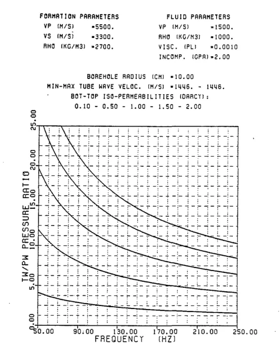
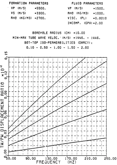
The ratios of tube wave amplitudes to P wave amplitudes are shown in Figures 5 - 8 for the simple case where"
=
rp=
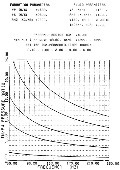
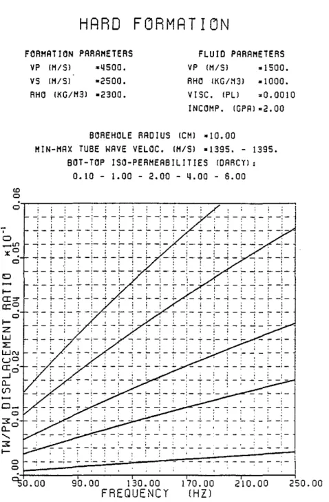
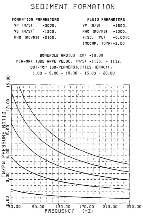
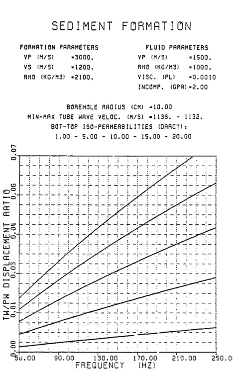
O. The first comparison made is that of the ratios of p,ressure amplitudes inside the borehole fluid. This is useful for interpreting the hydrophone data. The second comparison is that of the ratios of displacements that may be measured by a borehole seismometer locked to the borehole wall. Only the component of the displacement along Zbis considered. The tube wave particle motion at the borehole interface is highly elliptical and it is important to specify the component of displacement under consideration. Owing to the much larger amplitudes of tube wave's in the fluid it is preferable to use hydrophone data as opposed to geophone data to detect highly permeable zones. The borehole acts essentially as an ampl!tler. The tube wave pressure amplitudes in the fluid diminish with increasing frequency. The displacement ratios in the formation increase with frequency. Higher fracture permeability yields higher tUbe wave amplitudes. For a given fracture permeability, the "harder" the formation is, the higher the tube wave pressure amplitude in the fluid (Figure 5a, 6a, and 7a), and the lower the tube wave displacement amplitude in the formation (Figure 5b, 6b and 7b).
Figure 8 shows the effect of the borehole radius on the TW /PW pressure ratio. When the radius decreases the fluid volume decreases and. for a constant fracture permeability, the TW/PW ratio balances this decrease by increasing (Eqs. 9, E.8 and 6).
Field Examples
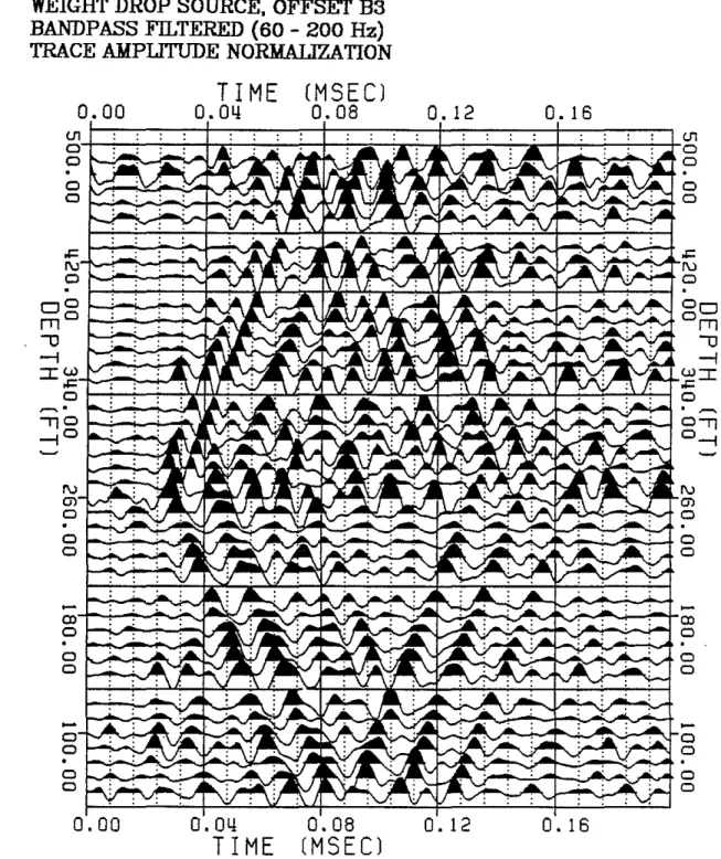
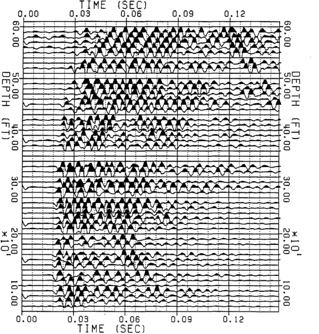
Field examples of tube wave generation in a borehole which intersects open fractures in granite are shown in Figures 1. (Tyngsboro, Mass.) and 2. (Hamilton. Mass.). These examples are pressure measurements in the borehole fluid. Comparison of data from the televiewer and the tUbe waves show a good correlation between tUbe wave generation and open fractures.
For the Tyngsboro data, the tube wave to P wave amplitude ratios were calculated as a function of frequency in well #3 for three fracture depths: 253', 290' and 471'. Due to weak P wave signals these values have relatively large error bars (in average about ±3 in the TW /PW ratio). These values are super-imposed on the theoretical iso-permeability curves of a granite model with a borehole radius of 7.6 em with"
=
rp=
0 (Figure 9). The trend of the data follows in some sense the theoretical curves. The permeability ranges between aprroximately 0.1 and 0.5 Darcys. These values are consistent with other permeability calculations in fractured granite as compiled by Brace (1980).However, preliminary comparisons between the observed flow and the estimated flow (calculated from the theoretical permeability, an estimated fractured zone width and a pressure head) show that the the estimated flow is lower than the observed one. This could be due (by order of importance) to (1) an over-estimate of the effective fracture distance; which means that only a part of the distance contributes to the volume ejected, therefore, a smaller volume is ejected for an observed TW/PW ratio; (2) an inclined fracture for which, if the model is used with"
=
0, would yield a lower bound of the permeability, thus, a lower flow; and (3) the perhaps inaccurate assumption of linear laminar regime of flow; this' would yield a lower volume ejected and a(
lower estimated fracture permeability. More field data are being processed at the present time and the results will be further compared with those obtained from the model. This will be the subject of an forthcoming paper.
CONCLUSIONS
Tube waves can be used to detect open fractures intersecting a borehole and to determine an eqUivalent fracture permeability using tube wave to P wave amplitude ratios in the borehole fluid (pressure ratio). It should be noted that the tUbe to P wave pressure ratio in the borehole fluid is approximately 3 orders of magnitude greater than the displacement ratio in the formation. For this reason it is preferable to use hydrophone data instead of wall-locked borehole geophone data, to locate these permeable zones. It is important to mention that a number of assumptions were made in this study and a complex "equivalency" was established between the two-dimensional cartesian geometry and the circular crack model. Another fracture model based on the static compression of an thin ellipsoidal or penny-shaped crack was developed. The comparison shows that the fracture effective distance is representative of the fracture radius. The parallel wall fracture model was applied to VSP data from Tyngsboro and Hamilton, Massachusetts. The results show a reasonable agreement with data.
ACKNOWLEDGMENT
The authors would like to thank Ernest Hardin from MIT/ERL for the processing and display of the data. This research was partially supported by the Full Waveform Acoustic Logging Consortium at M.I.T.
REFERENCES
Beydoun, W.B., Cheng, C.H. and Toksoz, M.N., 1983, Detection of Subsurface Fractures and Permeable Zones by the Analysis of Tube Waves: Annual Report FWAL consortium, MIT/ERL.
Brace, W.F., 1980, Permeability of crystalline and argillaceous rocks: Int. J. Rock Mech. Min. Sci. & Geomech. Abstr., v.17, p.241-251.
Cheng. C.H., 1978, Seismic velocities in porous rocks direct and inverse problems: Sc.D. thesis, M.LT., Cambridge.
Cheng, C.H. and Toksoz, M.N., 1981, Elastic wave propagation in a flUid-filled borehole and synthetic acoustic logs: Geophysics, v.46, p.1042-1053.
De Wiest, R.J.M., 1969, Flow Through Porous Media: AcademiC Press, New York, Eshelby, J.D., 1957, The determination of the elastic field of an ellipsoidal
inclusion, and related problems: Proc. Roy, Soc. London, Ser. A, v.241, p.376-396.
272 Beydounet
at
Huang, C.F. and Hunter, JA., 1981a, The correlation of "tube wave" events with open fractures in tl.uid-tl.lled boreholes: Current Research, Part A, Geological Survey of Canada, Paper 81-1A, p.361-376.
_ _'-- " 1981b, A seismic "Tube Wave" method for in-situ estimation of fracture permeability in boreholes: S.E.G. Preprint Series, 51st Annual International Meeting, Los Angeles, v.1, E1.4 p.23-46.
Johnston, D.H., Toksoz, M.N. and Timur, A., 1979, Attenuation of seismic waves in dry and saturated rocks, II. mechanisms: Geophysics, v.44, p.691-711.
Korringa, J., Brown, R.J.S., Thompson, D.D. and Runge, R.J., 1979, Self-consistent imbedding and the ellipsoidal model for porous rocks: J. Geophys. Res., v.84, p.5591-5598.
Kuster, G.T. and Toksoz, M.N., 1974, Velocity and attenuation of seismic waves in two-phase media: Part I. theoretical formulations: Geophysics, v.39, p.587-606.
Landau, L. and Lifchitz, E., 1976, Mecanique des Fluldes, MIR Publications, Moscow.
White, J.E" 1965, Seismic Waves, Radiation, Transmission and -Attenuation: McGraw Hill Book Company.
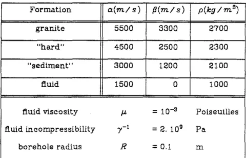
Table 1.Physical parameters used in thisstudy
Formation a(m/s) fJ(ml s) p(kglm3)
granite 5500 3300 2700
"hard" 4500 2500 2300
"sediment" 3000 1200 2100
flUid 1500 0 1000
flUid viscosity J.L
=
10-3 Poiseuilles tl.uid incompressibility 7-1=
2. 109 Pa borehole radius R=
0.1 m ( ( ( ( ( (APPENDIXA: TWO-DIMENSIONAL SOLlmON OF FRACTURE FLOW
The volume of fluid ejected from the fracture into the borehole (fracture closure) in T/2 is derived from the calculation of the injected fluid volume from the borehole to the fracture (fracture opening) in T/2. The net change of fluid dq in a volume element L (t)ds is due to the volume of fluid injected into the fracture (fracture opening) and the compressibility of the fluid (no mass is generated or lost in the element). During a time increment dt, this total change is
-dq dt
=
dL(t) dsdt+
L(t)i'ilp(s,t) dsdtdt at (A.l)
where i' is the fluid compressibility and dL(t)/ dt =c..>(o sin(c..>t), the velocity of the fracture wall. The net storage given by (A.l) must equal the net volume of fluid (aq (s ,t)/ as) dsdt flowing into the dil!erential volume, giving
~
[ K L(t) ap(s,t) ] =L(t) ilp(s,t)+
dL(t)as f-J- as i' at dt
Setting a2 =K/f-J-i' and Q(t) = c..>(osin(c..>t)/ (i'L(t», the folloWing equation is
found
(A.2)
with the boundary conditions for pressure (Assumption (4» p(s=R,t) P(s,t=O) ilp(s,t)/as = Po for all t ;" 0
=
Po for all s ;"R =0 s-.oaEq. (A.2) is a one-dimensional inhomogeneous dil!usion equation. The heat conduction analogy corresponds to a semi-inflnite half-space (s;"R) having a2 as thermal dil!usivity and a time varying heat source Q(t). The second condition assumes that the dil!usion process is over before T/2, since the process is reversed every T/2. The last condition states that there is no fluid flow in the fracture far (s»R+d) from the borehole intersection.
The solution to this partial dil!erential Eq. (A.2) is found by the standard Laplace transform method
•
where er! (z)
= .;..
f
e-t2d~
is the error function. V1[ 0274 Beydoun etaL
Thus, the pressure gradient is
~.J.l
=__
1_j
Q(r) ex [ _(S-R)2 ] (t_r)-1/2 dras
av'iTo
P4a2 (t-r) s ;;" R (A.4)The rate at which fluid flows is given by Eq. (2). By caicuiating the volume injected into the fracture for the maximum fracture displacement 2<:"0' we can obtain the maximum volume injected in a finite amount of time. This maximum volume occurs during a time interval of t
=
T12. Therefore the volume of fluid forced into the fracture from the borehole in T12isT/2 Vw=
J
q(s=R,t)dt o or explicitly, ( where (A.5) T/2 t F(r.>,<:"olLo)=
r.>J J
o 0 1 - (<:"01 Lo)cos(r.>t) sin(r.>r) 1 - (<:"01Lo)cos(GJr) (t - r)* dr dtSince L(t) is T-periodic and T12-symmetric we can directly infer from (A.5) the fluid volume forced from the fracture into the borehole. The right hand side of (A.5) is different in sign during the fracture closure, because the fiuid fiows in the opposite direction. Therefore the volume of fiuid injected into the borehole in T12 is given by Eq. (3).
Computation shows that for increasing frequency, F(r.>, <:"01 L o) decreases. As the frequency increases less fluid is ejected into the borehole. For <:"0« Lo (Assumption (1)), an asymptotic expression for F can be found by interchanging the order of integration in the (r,t) plane:
T/2
F(GJ,O) =2GJ
J
(T12-t)*sin(GJt) dt o(
APPENDIX B: TUBE WAVE SOURCE
The borehole geometry is taken to be axi-symmetric with respect to the
z.
axis. The generated tube wave potential in the fluid is chosen to be(B.!) where C is a parameter, depending on the medium and the fluid properties. In this problem, C will depend also on the fracture parameters.
The tube wave pressure amplitude in the borehole fluid pT and its displacement amplitude in the formation along z.,
uJ,
are then given by, ignoring the sinusoidal time dependence for the moment:PT
=
PI G)2 C Io(nr)rsR-u!
=
A[kKo(lr) + mGKo(mr)] r;;"R+ where G = _,..;;2;:.l!:.,{3_2K~l(.::lR:..:.)~: k (c2-2{32) K,(mR) A=
.:C,..;;n.:....:.I~l(:..::n:.:R.!....)~(2:.!:{3:....2_-=..C2..!....) 1 c2 K,(lR)Tube wave volumetric strain in the fluid is defined as
(B.2) (B.3)
(B.4)
(B.5)
where
uJr
anduJ.
are the radial (perpendicular to z.) component and the component alongz.
of the tube wave particle displacement in the fluid.The relations between the potential and the displacement components are
uJr
=
oiflJIOr andTherefore a simple relation arises between the volumetric strain and the potential
(B.6) where <;,2 is the Laplacian operator. Caicuiation of Eq. (B.6) with (B.l) yields
(B.7) The double integral in (7) is easily computed, since the variabies are separated
2:76 Beydoun etaI.
- V(K)
=
4rrR C(K) (2 - 021 a'j) J1(nR) kinc
(
The parameter C depends on the fracture parameters and therefore couples the fracture movement to the tube wave propagation. The tube wave pressure in the fuild and displacement in the formation are now linked to the fracture dynamics (Eq. (B.2) and (B.3)). Using Eq. (6) and (3) we finally obtain
(RB)
(
, (
(
TYNGSBORO WELL No.2
WEIGlIT DROP SOURCE. OFFSET B3
BANDPASS FILTERED (60 - 200 Hz)
TRACE AMPLITUDE NORMALIZAnON
O. 16
T I ME
(MSECl
0.00
O.O~0.08
0.12
~d=::;::=::;::::;:::t:i=::;::::::;::::;::::=t=:;::::;~:;;~t=~~;:::::;i;:=t=;::=;::===+~
o
0 o 0o
0 ~.,,0
I--..."-'~"" -i0~'-'""' ___O. 16
O.
12
~~i;:Al:::±?O~::K:O::=H~
YO;~N~~'-";':"'--!,,"'0a.;.---...-,o-="---'
nr'''- ;..-.-....-...-...~ 0 ---""'-J 00.08
(MSECl
O.O~TIME
0.00
~+-...;.._..-!'-...;-,. o !-;...a""";""";-{"A o "-'-..~~.~ o I - - - v " , ~ ~~
A:\.-4."';';""'-..-+~
o "'_~!'v-V~""'''''''''~'--"f 0O~~~~~~~O
Figure 1: Example of fracture generated tUbe wave in a VSP, in Tyngsboro, Mas-sachusetts.
278 Beydoun etal.
(
BRmON (HAMILTON) WELL No.2
EXPLOSION SOURCE, OBSERVATION WELL
BANDPASS FILTERED (60 - 250 Hz)
TRACE AMPIJTUDE NORMALIZATION
(
0.00
'l,j:""0
- '
o
o Ul o o o-
o oo
0.00
TIME
0.03
-,0,03
TIME
(SEC)
0.06
0.06
(SEC)
0.09
0.09
0" 12 O. 12 ( CJ) 0 0 0 ( UlO °fTl ' " 1 ) 0 0 " "::r:
( -='l 0 " ".
~ 0 0 ( Ul 0 0 0 ( ~;l(.
... 0 0o
_
o o oFigure 2: Example of fracture generated tube wave in a VSP, in Hamilton, Mas-sachusetts.
P SOURCE
X
/
"
/'(
' - .1 __ -- SENSORS-,....-\-
--FRACTURE ZONE TUBE WAVES TIME (SECONDS) 0.2¥~'«
Figure 3: Schematic diagram of the mechanism of generation of tUbe waves (left) and an actual VSP section (from Huang & Hunter, 19B1b) showing the fracture generated tube waves.
280
...
Z
Beydoun etaL ~n
Formation
\
\\
\
...
X
(Angle orientation
Flgure 4: Fracture model used in this study
GRAN IT E FI)RMATII)N
FLUID PAAAHETEAS VP IH/S) -1500. RHO [KG/H3) -1000. VISC. IPLl -0.0010 INCOHP. IGPAJ-2.00 PARAHETEAS -5500. -3300. -2700. FORHATION VP IH/SJ VS IH/S) RHO IKG/H3JBOREHOLE RAO I US [CHI -10.00
MIN-MAX TUBE WAVE VELOC. [HIS) -1446. - 1446. BOT-TOP ISO-PERMEABILlTIES !ORRcn:
0.10 - 0.50 - 1.00 - 1.50 - 2.00 250.00 210.00 170.00 (HZ) , . . . , .
.
. . _ l.... _: _ ~ _~_ 4 _:_ -4 _ '_ _! _ .:- _!_ , i ' i i '- ;- -!-T - i- ""1 - :- ~- r-;---.---,---.-
., ,. I. . . . ,, , , ' , , , . ., , . . . , . . ..
. . -~~-~~-~-:-~-:-~-~~-~-:-. . . . . , I " , ' - -i' - ,.... -i - ;-. -: - .:.. -: - -+ -:- -: - -- -: - .;... -,--i- -+-:- -;-i- -i-"i- -i- --:- -:- -i -:- --:-:--i-90,00 130.00
FREQUENCY
o o lCn-c--:'\-,--,--,--,---,.--,.----,---,-,-,-.,--,---c--,--,-..,..., ! !;- !
-!- ! -
r
i -
r--! -!
-!- -: -;- -: - ;--! - :-
-;-1.. _;_ ..l _:.... ....: _ :..._~_ .;- _;_ ..:. _ ~_ ...: _ :... ...; _ :- _:_ ~ ~ ! ~ o o o C\I 10 "S0.00 >-0:0 a:o W~ a: ::> (/") (/")0 WO a:' a...~ :3: a... '-:3:0 >-0 onFigure 5a: Tube to P wave pressure ratios as functions of frequency and per-meability in a granite.
282 Beydoun et aI.
c
GRAN ITE FORMATION
(( FLUID PARAHETERS VP lH/S) -1500. RHO IKG/H3) -1000. VISCo lPL) -0.0010 INCOHP. IGPA) -2.00 -2700. PAAAHE1EAS -5500. -3300. FORHA1ION VP IH/S) VS (HIS) RHO IKG/H3)
BORE~OLE RADIUS ICH) -10.00
HIN-HAX lUBE WAVE VELOC.· IH/S) -1446. - 1446. B01-TOP ISO-PEAHEABILIT IES IDAACll:
0.10 - 0.50 - 1.00 - 1.50 - 2.00 ( ( ( ( -+
-:-.. :-,=-1
~ ~~-~->~
- T-,- -, -;--
~-
~-: -
~-;- ., -;- -, - :...
--i - ~ -: -j
90.00 I~O.OO I~O.OO 2'10.00 250.00 FREwUENCY (HZ) · . . . . --'·_
.....
_.-
. .....
_.-
. ...-' - - '. ._....
. .- ~. -,-. ~..
..
. . , , , , , , , , -:-:- -:--:- -:--:' _.--:"" 0:'--'-"-.-,-. ....,....-.'---'---"--'-.-:-.--,---,--;-.---,--,--:-;,..,..--,--,--,-., : : ! : ! ! ! -: - t- -: - t - i- ""t -i- -: -r- -: - :-
-i- -: -: j _ 1... _!_ 1. _!_j _:... j _ l.. _; _ 1.. _i_.!. _ '_ j _ l... j _ : ! 1 ; i . ! . . . . , . . . , . ,.
..
. . . . ~---.---,----~---,-~-· . ..
, . . . . ~O.OO o...
cr", a::~ o...
Z l.l.J ~ l.l.J'" W O cr' --,0 0.. <Il 'l' o-'"
x-:
o 0", o :J:' 0..0 "-:J:...
o oFigure 5b: Tube to P wave displacement ratios as functions of frequency and permeability in a granite.
HARD FORMATION
FLUID PAAAMETEAS VP {H/SI -1500. AHO {KG 1M3 I -1000. VISCo IPLl -0.0010 INCOMP. IGPAI-2.00 PAAAHETEAS -4500. -2500. -2300. FOAHATION VP (H/SI VS IM/S) AHO IKG/M31BOREHOLE RAO I US {CHI -10. 00
HIN-HAX TUBE HAVE VELOC. {H/SI -1395. - 1395. BOT - TOP I SO-PEAHEAB I LI TIES IOAACTI:
0.10 - 1.00 - 2.00 - 4.00 - 6.00
-i
250.00 210.00 170.00 (HZ) ~-~~-~-!-+-!-~-~~-~-i--.-I - -,- -
I , ,.
. . ... _1_ .... _. . . . 90.~0 130.00 FREQUENCY--: _L _:_
! \ ;....;-:
: i ; ; : : : ; ; .-' - l - - - -'-
~--
~-
~ -'-o o K1'~---~---~-1-1-1-
~
-
r
-I-
T
-I-1-
i-
i -
i-
-I -
T
-1-1
:-7-~l-~~-r-i-T-~--1-~l-r-i-1 -!- -:- -: -T -;...--i - :- -i - :--i-+-:-
~- :-
~- :-
-:-~O.OO o o o o o C\J o t-O:o a:o !.W~ a: :::> <I"> <1">0 !.Wo a:' Q...~-Figure 6a: Tube to P wave pressure ratios as functions of frequency and per-meability in a "hard" formation.
284 Beydoun et aI.
HARD FORMATION
( { FLUID PARAHETERS VP IHISI _ I 500. RHO IKG/H31 -1000. VISC. IPLl -0.0010 INCOHP. IGPAI -2.00 PARAHETERS -4500. -2500. -2300. FORMATION VP IHISI VS IHISI RHO IKG/H31BOREHOLE RADIUS ICHI -10.00
HI N-HAX TUBE WAVE VELOC. IHISI -1395. - 1395. BOT - TOP I SO-PERHEAB 1LI TIES IDARcn:
0.10 - 1.00 - 2.00 - 4.00 - 6.00 { ( - - : : -, - ; -,
.
. , . . . -,_..... .
-,- ... -,.... ....- . -''';- -:-'0+ -:- -: - ' ~-~-i- -:- -;-...,. -;--:- i-, I , • , , , I f -i - !""" -; - T -;- ""t -;- --: -r- -; - :- -;- .... -
~- """"! - :- -: - : ; -J_L_;_i_~_l_LJ_L~_i_ ~ ! o-'"
"C:
o CD 0 - , - -,---,---,---,---,---,---,---,--_ _--;; -,---,--...., o ";" l ( 250.00 210.00 , -:-....:-:...:_:....-:-: : : ' : : 170.00 (HZ) - ...., -,-~-.-, , , • < • • ., , , , , , , , , , -_.
- - _.--_.-
- - - _.,- ,- -; - !
--
~
-
~
-; -
~
-'=
~
='_
J
=
C
=
=
c
t
1
90.00 130.00 FREQUENCY , - ,... - : - ~ : - ""7 - : - ...; - ~ - ' - ~ - ; - -:- - - ..: - - - - ~ -~-...:-.:... -:- ~.-:-...;.-:-: ! : : ! : : , . ~ . . , . . , . . . . , . . , -;-"!- - ! - -;--f-'~ -~ ~ - : - -f-'"!--:-7-:- . -:- -;- :-._~-o"""
( I ' "a:C:
o"""
Z W ::E W'" W O ( I ' -,0 CL (f) 0 _ o ::l:' CLO"
:::c , ; , ; ; . , :"""15
,~""L
~-
-;--
-7:ft-:-"
.;._:-
~ _:- _:-±::-
-
-=~
-' -
-=-
- -- -=-
- ---- -=-
~. - --
--=J-
--
--
-,-~o.ooFigure 6b: Tube to P wave displacement ratios as functions of frequency and permeability in a "hard" formation,
SEDIMENT FORMATION
FORHRTION PARAHETERS VP IH/SJ -3000. VS IH/SI -1200. RHO IKG/H31 -2100. FLUID PARAMETERS VP IM/SI -1500. RHO IKG/M3J -1000. vrsc. IPLI -0.0010 INCOMP. IGPAJ-2.00BOREHOLE RADIUS ICMI -10.00
MIN-MAX TUBE WAVE VELOC. IH/SI -1136. - 1132. BOT - TOP I SO-PERMEAB III TIES 10ARcn:
1.00 - 5.00 - 10.00 - 15.00 - 20.00 o o
""
...
-.,..---,
250.00 210.00 170.00 (HZ) 90.00 130.00FREQUENCY
t -i- t -i-: -i-'~- ~ -:-: -i-:-i-: - ; : - : -:-_:_ i. _i_ i _l-J _~ _i_':" _:_ i. _~_J _L. --.:_:.... _:_ "'SO. 00 o o <:> o o
'"
I -eI: 0:0 oWen
0: ::::> en en wo 0: 0 a....to 3: a... ... 3:0 1 - 0'"
Figure 7a: Tube to P wave pressure ratios as functions of frequency and per-meability in a ··sediment."
( 286 Beydoun etat
SEDIMENT FORMATION
( FLUID PARAMETERS VP IM/Sl -1500. RHO IKG/H3l -1000. VISCo IPLl -0.0010 INCOHP. IGPRl-2.00 PARAMETERS -3000. -1200. -2100. FORMATION VP IM/Sl VS IM/Sl RHO IKG/H3lBOREHOLE RADIUS ICMl -10.00
MIN-MAX TUBE WAVE VELOC. IM/Sl -1136. - 1132. BOT-TOP ISC-PERMEA8 IUT IES IOARcn:
1.00 - 5.00 - 10.00 - 15.00 - 20.00 ( r-o o-r-...,...,...--,---...,---,----,--...,...,~--...,
-1 -
~
-j-
~
-:-
~
-!-
~
-
~
-i-
~
-i-
~
-;-
~
-
~
-: -
~
-:-
J : : : : : : : : : . : : : : . . I ~_~_l_~_!_~_~~_~~_~_!_~_~_ _~~ :_l "'Su.OO ( · . , ,·
....
·,- -., - ' - '.
, - -'-,. ,. -,- ' , · , . . . , , , , ,--
- -.-- .-~
- - -; -
~ ~'~
:
~.~
=
=: ;
=
=
==
1
; ;
: ,
I
---~-~~---l -·-1-'-~-r-~-7-·-~----~~----1- ;- _: -
~-;-
~-:-
~-
~_: - - -'''-'';- ' .
, i
-~~~.
~-_~~.
__
~~~~-~-_~~~~_~~l!
90.00 130.00 170.00 2~0.00 2~0.00 FREQUENCY (HZ) o o....
ZO'"
UJo ::E UJ U a: --,,,, 0..0 ( I ) ' o-Figure 7b: Tube to P wave displacement ratios as functions of frequency and permeability in a "sediment."
HARD FORMATION
FLUID PARAHETERS VP [H/SI -1500. RHD [KG/H31 -1000. VISC. [?LJ -0.0010 INCDHP. [GPAI-2.00 PAAAHETERS -4500. -2500. -2300. FDRHRTIDN VP [HISI VS [HIS I RHD [KG/H31 F R E QUE N C T [HZI -150. TUBE WAVE VELDCIH [H/SI -1395. BDT-TDP ISD-PERHEABILITIE5 [OAROI: 0.10 - 1.00 - 2.00 - 4.00 - 6.00 - -'-
--
{---,
_!
,__ ... ,_ ... _...
l.. _._ ! ~ : ! ! ! ! ! ! : '-l-. !--+.--':-+-:-4-!--:-;"-:-i !--+.--':-+-:-4-!--:-;"-:-i !--+.--':-+-:-4-!--:-;"-:-i i i r-i- ~ -i- ~ -;- ~-;- -~-, . , . . . . ' -,... -,-..- -,-..
. ... -,-,...
, .- . - ... - . .- -,- t~-t-!-t-i-j-~~-~~-. . . . , . . ,.
. ..
~... :--~-, -:--~- ""7 ... :- -: - :- --; ...~-~-.
. . . , ,--_._--,---
, , , , , . ,.
-._--
,. , ...---_.- _.---
. . . ., , , , , . - t- -: . . . , --;- ~ -;- + -:- ~ , . . . ..
..
... - ~ -~... ..;.. ... ! - ...:. - : - --! ... 3: Q... "-3:0 .... 0'"
o o ~.--.,-.,--:-.,--:-r-....,....,-.,-.,-.,-.,-.,--.,----'----'-"" o o o C\J o....
CI:o a:o w~ a: :::J U1 U1 0 wo a: . Q...~g
-i ... :- -i'" ~ -;- ~ ....- _ _ _ _ _ c , _ j "b.50 4.40 8.30 12.20 16.10BOREHOLE RRO I US (eM) 20.00
Figure 8: Tube to P wave pressure ratios as functions of borehole radius and permeability in a "hard" formation.
288 Beydoun etal..
GRAN ITE FORMATION
( FLUID PARAHETERS VP IH/SI -1500. RHO IKG/H31 -1000. VISCo IPLl -0.0010 INCOHP. IGPA).2.00 PARAHETERS -5800. -3300. -2700. FORHATION VP IH/SI VS IH/Si RHO IKG/H31 (
.'"
( ( ~ ~ r-. r-. r-. r-. x x Q) Q) <':i (')a;
Q) ~ ~ '- '-.Q .Q-- --
0 0 ttl ttl '-'--
-.
-(') r-. 10 '<t C\l
...
•
rJi
(') (IJ 'to«
Q) :::E;s:
0 Q)a:
-0 ttl CD C!J (IJ c C!J 0c Z c>-
ttl I- (J o ttl'
-~ C\l...:
ttl "0 c.i ttl-
en Ol o --o o R::-,--,--,--,--.;--,--,--,--,-...,-"<':"""...,---,----,----,---,---,---,--,--.,.--, ( l t -!-t - ;_. -: - r- -; --:- -i-. , . , 80REHOLE RADIUS ICH) -7.60HIN-HAX TUBE WAVE VELOC. IH/S) -1446. - 1446. BOT - TOP I SO-PERHEAB III TIES 10AReTl:
0.10 - 0.20 - 0.50 - 1.00 - 2.00 o o <0 >-0:0 0::0 W~ 0:: ;:) (f) (f) WO 0::0 . . ' • ' o...ci
-'-.T .-:- -,
O~5d :~O
- , - ,~'~ ~:=~~~~~
t
j=
r
T
I _'_
:~:
==:
-;->-0 ' , ' ,Q' 1il . ' '.' , , , , , , , ,
=-
:=H=T-i=i=J~=,4-:·:- ~.--EI
"~
~ r~=q=:=FH=H~~I~=j-~~-:==l
•
"20.00 60.00 100.00 140.00 180.00 220.00 FREQUENCY (HZl-Figure 9; Data versus theoretical tube to P wave pressure ratios as functions of frequency and permeability in a granite.