Dynamic Exoskeleton: Mechanical Design of a Human Exoskeleton to
Enhance Maximum Dynamic Performance
by
Jacob Tims
Submitted to the
Department of Mechanical Engineering
in Partial Fulfillment of the Requirements for the Degree of Bachelor of Science in Mechanical Engineering
at the
Massachusetts Institute of Technology
June 2016 MASSACHUSETTS INSTITUTE OF TECHNOLOGY
JUL 082016
LIBRARIES
ARCHIVES
0 2016 Massachusetts Institute of Technology. All rights reserved.
Signature of Author:
Signature redacted
7
Certified by:
Accepted by:
Department of Mechanical Engineering
ay6, 2016
Signature redacted_
Sangbae Kim ssociate Pro of Mechanical Engineering Thesis Supervisor
Signature redacted
Dynamic Exoskeleton: Mechanical Design of a Human Exoskeleton to
Enhance Maximum Dynamic Performance
by
Jacob Tims
Submitted to the Department of Mechanical Engineering on May 6, 2016 in Partial Fulfillment of the
Requirements for the Degree of
Bachelor of Science in Mechanical Engineering
ABSTRACT
An exoskeleton was designed with the primary goal of enhancing the maximum dynamic capability of a human, thus allowing the user to run faster, jump higher, or traverse challenging terrain. This paper presents the mechanical design of an alpha prototype with a focus on increasing the maximum vertical jump height of a human. High torque motors were constrained to the body with two degrees of freedom using carbon fiber, aluminum, and other lightweight materials. The exoskeleton actuates the hip joint by comfortably providing force to three points on the body. Human testing showed a maximum increase in jump height of 13%.
Thesis Supervisor: Sangbae Kim
TABLE OF CONTENTS Abstract 3 Table of Contents 4 List of Figures 5 1. Introduction 6 2. Background 6
2.1 Overall Design Approach 6
2.2 Model and Simulations 7
3. Mechanical Design Considerations 7
3.1 Degrees of Freedom and Alignment 7
3.2 Effectively Transmitting Torque to a Human Body 8
3.3 Strength vs. Weight 9
4. Exoskeleton Prototypes 10
5. Testing, Results, and Conclusions 11
5.1 Human Testing 11
5.2 Conclusions 11
6. Acknowledgements 12
LIST OF FIGURES
Figure 1: The alpha prototype of a dynamic human exoskeleton 6
Figure 2: Diagram of the vertical jump simulation 7
Figure 3: Alignments of the two degrees of freedom 8
Figure 4: Modeling human leg curvature 8
Figure 5: Strain distribution in a composite beam 9
Figure 6: FEA of an aluminum part which was optimized for weight 10
Figure 7: Forces produced by the exoskeleton 10
Figure 8: Adjustability in the exoskeleton 11
Figure 9: Measuring maximum jump height while wearing the dynamic exoskeleton 11
I. INTRODUCTION
Human exoskeletons have tremendous potential for medical, industrial, and military applications. There are several being developed in research and industry today which augment the human body and aim to improve performance. The Soft Exosuit research project at Harvard is being designed to decrease the metabolic cost of walking in both healthy and impaired individuals through the use of textiles and Bowden cables [1]. The HULC exoskeleton, developed by Lockheed Martin, transmits load to the ground through titanium legs and allows soldiers to carry heavier loads for longer distances without injury [2]. The HAL exoskeleton was designed by Cyberdine to improve the walking gait of individuals with lower limb disorders or to assist healthy individuals in carrying heavy loads [3]. Other notable exoskeletons include the EKSO by Eksobionics, the ReWalk Personal Exoskeleton by ReWalk, and the Stride Management Assist by Honda
[4] [5] [6].
Many of these exoskeletons are well designed and highly effective at reducing metabolic cost or increasing load bearing capability. However, it is believed that there are no exoskeletons being developed which enhance the maximum dynamic performance of a human, such as sprinting or jumping. Natural human motion is heavily dynamic, so the next major step for exoskeleton technology is to design systems which enhance, and don't inhibit, dynamic motion.
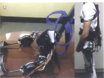
The goal of this project is to create an actively powered exoskeleton that demonstrates the ability to improve dynamic performance. The metric of success chosen is the maximum vertical jump height, as this is a relatively simple motion to study and simulate and safe to test. This paper discusses the mechanical design of a jumping exoskeleton prototype, as shown in Figure 1, followed by the results of human testing.
6
Figure 1: The alpha prototype of a dynamic human exoskeleton.
II. BACKGROUND
A. Overall Design Approach
In order to enhance the dynamic capabilities of a human an exoskeleton must increase the force output of the 'feet without significantly inhibiting the user's natural leg motion. This can be accomplished through several means. Honda's Stride Management Assist directly actuates the joints involved in the motion, in this case the hip, while Lockheed Martin's HULC exoskeleton actuates the foot relative to the torso without directly actuating a leg joint. This method is not conducive to dynamic motion since the mechanism must extend all the way down the body and increase the moment of inertia of the leg. Because of this, the design of the dynamic exoskeleton employs the method of directly actuating the hip joint.
The hip joint is specifically selected because it performs more work than the knee or ankle in a vertical jump [7], so actuating at this point should allow the user to increase his maximum dynamic performance. Placing the motors here also concentrates the mass of the exoskeleton very near to the center of mass of the user, which minimizes the moment of inertia of the legs and allows for higher angular acceleration.
B. Mode/ aid Si mm/a/ion
To mathematically analyze and predict the effects of actuating the hip joint during a vertical jump, a simulation was performed using a modified version of the human model developed by K.B. Cheng [8]. This model simplifies the kinematics of a jump to four segments as shown in Figure 2, with all muscle forces represented as torques applied to three frictionless revolute joints. The modified simulation added 6 kg of mass to the torso and 100 Nm of torque to each hip to represent the added mass and torque of the exoskeleton. The modifications to the simulation increased the vertical jump height by 520%, confirming that an exoskeleton could be effective at improving maximum dynamic performance [9].
I,
JL
T3
\2T
1
III. MECHANICAL DESIGN CONSIDERATIONS
A. Degrees of Freedom and .- 1/gnmvenl
A vertical jump is a complicated maneuver which requires many degrees of freedom to maintain balance and maximize power. In order to not interfere with the body's natural motion, the kinematics of the exoskeleton and the human body must match as closely as possible. A human hip is a ball and socket joint, Which means it has three degrees of freedom: extension, abduction, and rotation. Video analysis showed that rotation had a minimum impact on the vertical jump, so the exoskeleton was designed to allow for freedom in extension and abduction.
If the exoskeleton were rigidly attached to the human body, these two rotational degrees of freedom would need to be perfectly aligned to the corresponding joint. To practically achieve this is impossible and unnecessary. The exoskeleton design took advantage of the natural compliance of the human body to make up for the lack of kinematic alignment. As seen in figure 3, the current design aligns the axis of the rotation of the motor and the extension of the hip as closely as possible and leaves the axes corresponding to abduction offset approximately 8". This causes sliding at the interface of the leg pads which is accommodated by a slippery ABS plate attached to the leg.
The vertical jump simulation the human body to four connected by three actuated Figure 2:
simplified segments joints.
aligned motor axis
Figure 3: The motor's axis is aligned with
the center of rotation of the hip joint. The second abduction axis is offset by 6-8 inches.
B. Ej(ective/y Transmitting Torque to a Human Bocfy
Adding external actuation to a human body is non-trivial for a number of reasons. In addition to the alignment issues, correct placement of forces is crucial to the safety and comfort of the user. The exoskeleton design accounts for this in a few different ways.
First, large surface areas are used wherever force is applied to rmrunuze pressure. For the torso attachments, many off-the-shelf straps and braces were explored to find one which comfortably transmitted force across the chest and shoulders. For the leg attachments, large rigid custom-shaped pads were created to press against the leg in key areas.
Second, in one exoskeleton prototype adjustment features are built in to account for different body sizes. To accommodate different sizes of hips, the motor was attached to the back plate through a series of Delrin spacers which can be added to move the motors further apart. There are also two sets of slots to allow the. user to position the motor axis closer in alignment with the hip joint.
8
Lastly, several methods were employed to design features that closely match the curvature of the human leg to maximize the surface area of contact and minimize pressure. One method was to shape foam using heat and use it as the core for the carbon fiber layup. Quarter-inch green machining foam was cut into slabs on a band saw and heated up using a hot air gun. The slabs were then pressed around the leg of the user and held in place until it solidified into the curvature of the leg.
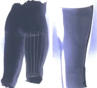
The other method employed was to scan and model the user's leg and 3D print a custom leg pad. An Xbox Kinect was used to scan the user's legs and build an STL file of the curvature and dimensions. As seen in Figure 4, while mostly accurate these models contained a significant amount noise and were built from overly complex polygonal surfaces which Solidworks could not modify. The files were therefore imported only as a reference.
To model the curvature of a portion of the user's leg like the thigh, splines were used to trace the outline of the STL reference at 22.5-degree sections running vertically down the leg. Another was made following the curvature horizontally. The vertical splines were then lofted around 180 degrees following the profile of the horizontal spline to create a smooth, accurate, and machinable model of the user's leg.
Figure 4: The STL file is traced with splines
Qeft) and the profile is lofted to create a smooth and accurate part (right).
C. Strength vs. We~ht
One of the most important considerations in the design of the exoskeleton was the weight. Simulations showed that even small amounts of mass added to the human body drastically reduced the maximum jump height. Yet the actuators used have a maximum output of approximately 180 Nm, which could easily damage weak points of an exoskeleton. Lightweight yet strong
design was critical to effective dynamic performance. The first technique employed to optimize for weight was to design for bending stress. The equation for stress
a
in a beam isMy a =
-/
where Mis the applied moment,
y
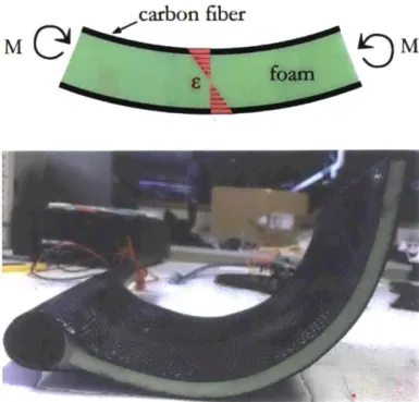
is the perpendicular distance to the neutral axis, and I is the moment of inertia. This shows that the material most highly stressed will be that which is the furthest from the neutral axis, or the material on the outside. Making this layer of material strong will make the entire beam strongeven if the material on the inside is lightweight or fragile, as shown in Figure 5. For this reason, carbon fiber was extensively used as the outermost layer of material, while the inside was either hollow or filled with lightweight foam.
The result was an extremely lightweight and rigid
structure which had the ability to be formed into various organic shapes useful for the exoskeleton.
Figure 5: The strain distribution in the composite beam allows the carbon fiber to take the vast majority of bending load.
Where metal was required, aluminum was used for its favorable strength to weight ratio, and Finite Element Analysis was performed in Solidworks to optimize for weight. The iterative design process to produce lightweight metal parts was as follows:
1) The aluminum part was designed.
2) Loads and boundary conditions were applied in the FEA and the simulation calculated stress and strain.
3) The stress profile was examined to find material which was under very high or very low stress. 4) Material which was highly stressed was built up,
thickened, or redesigned with greater support.
5) Material which was under low stress was taken out.
This process repeated until the part showed a relatively uniform stress profile, which meant that load was distributed evenly and it was optimized for weight, as shown in Figure 6.
Max: 1,049e+008
IMin: 1.312e+0041,
von Mises ([hmA
1.049e+008 9.614e+007 8.740e+007 7.866e+007 6.992e+007 6.119e+ 007 5.245e+007 4.371e+ 007 3.497e+007 2.623e+007 1.749e+ 007 8,752e+006 1312e+004 SYield str ength: 5.050e+ 008
F3
F
-/
/7i
Figure 6: FEA of an aluminum part which was optimized for weight.
IV. EXOSKELETON PROTOTYPES
Two versions of the dynamic exoskeleton were designed and fabricated to actuate the hip joint and increase the maximum jump height of a human. Both have similar functionality and construction, but one was designed for adjustability while the other was streamlined for weight.
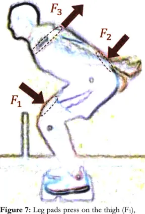
While the actuators lie next to the hip joint, force is applied in three different locations on the body, as shown in Figure 7. Two custom-shaped carbon fiber leg pads press on the front of the user's thighs, while two commercially available back braces apply torque to the torso. The first brace is a lumbar lower back brace with a semi-rigid ABS plate which presses on the lower back. The second is a fabric upper back brace which wraps around the shoulders and chest and pulls backwards during the
jump,
and is sufficiently flexible so that it does not impede the user's natural torso motion.Figure 7: Leg pads press on the thigh (F1), an ABS plate presses on the lower back (F2), and fabric straps pull back on the chest and shoulders (F3).
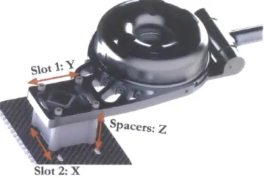
The leg pads are sandwiched with foam and attached to a hollow carbon fiber tube that fits into the abduction hinge on the motor output. The fixed side of the motor is connected to the torso attachment through a lightweight aluminum connector. In the adjustable prototype, there are three degrees of adjustability at this point through slots and spacers, as seen in Figure 8. Two slots allow adjustability in the X and Y directions, while interchangeable spacers allow adjustability in the Z direction. In the lightweight prototype, the aluminum connector is bolted directly to an aluminum back piece which wraps around the torso on both sides. From there, a rectangular carbon fiber tube is bolted on and extends up the spine, securing the fabric brace at the top and the lumbar back brace at the bottom. Lastly, a traditional climbing harness is secured around the user's upper thighs to inhibit vertical movement of the exoskeleton during a jump. Combined, these attachments distribute the load evenly across the body and effectively transmit torque to the hip.
Slot 2: X
Figure 8: Two slots allow adjustability in the X and Y directions, while spacers allow adjustability in Z.
The total mass of the adjustable prototype is approximately 6 kg, half of which is due to the actuators on either side. These actuators, very similar to those designed for use on the MIT Cheetah Robot [1 O], are brushless, 3-phase motors with a peak torque of 180 Nm. Each motor contains a single stage planetary gearbox with a 6:1 gear ratio, which allows the output to be highly back-drivable.
V. TESTING, RESULTS, AND CONCLUSIONS
A. Human Testing
Figure 9: Measuring maximum jump height while wearing the dynamic exoskeleton [9].
The adjustable prototype was the only version of the exoskeleton to undergo human testing. Three healthy human test subjects, hereby referred to as Subject A, Subject B, and Subject C, wore the exoskeleton over multiple jumping sessions to collect data. First, the subjects were asked to perform two vertical jumps without the exoskeleton to determine their baseline jump height. Then the subjects wore the exoskeleton and incrementally increased torque every two jumps as the height continued to be recorded, as shown in Figure 9. For Subject A and Subject B, the torque never exceeded 90 Nm, which is approximately 50% of the peak output of the motors. Subject C increased torque up to 165 Nm, which is approximately 92% of the peak output [9].
The testing results are presented in Figure 10. All three subjects exceeded their baseline jump height, which is represented in the figure with a dashed line. The best improvement in maximum jump height was 13% and was exhibited by Subject A, while Subject B improved by 5% and Subject C improved by 6%. The data suggests that the maximum jump heights of Subject B and C could be further increased if the torque of the exoskeleton had exceeded 90 Nm [9].
-.-Subject A - Subject B - Subject C C1 E 0.45 04 0.35 03 20 so 80 110 Motor Torque (Nm) 140 170
Figure 10: Jump height increases with torque for each subject. Baseline JUMP heights are represented by the dashed lines [9].
B. Conclusions
Human testing data clearly shows that the exoskeleton is effective at increasing the maximum jump height of the user, and that electric actuators are capable of effectively applying torque to the human body and increasing its dynamic capabilities. It is believed that this is the first actively powered exoskeleton to do so. There is plenty of room for further design iterations which could be more lightweight, form-fitted, mobile, and could increase the dynamic capability of a human in multiple ways. This technology, when further developed, has the potential to make humans faster, stronger, more agile, and more athletic.
VI. ACKNOWLEDGEMENTS
The author would like to thank Lockheed Martin for supporting this research, as well as Prof. Sangbae Kim and the Biomimetics Robotics Lab for their guidance and support on the project.
VII. REFERENCES
[1] Asbeck AT, Schmidt K, Galiana I, Walsh CJ. Multi-joint Soft Exosuit for Gait Assistance, in International Conference on Robotics and Automation (ICRA) (2015) 368711
[2] Lockheed Martin HULC Exoskeleton (Accessed 2016 April 28:
http://www.lockheedmartin.com/us/products/exoskel eton/hulc.html)
[3] Cyberdine HAL Exoskeleton (Accessed 2016 April 28): http://www.cyberdyne.jp/english/products/HAL/ [4] Eksobionics EKSO Exoskeleton (Accessed 2016 April
28): http://www.eksobionics.com
[5] ReWalk Personal Exoskeleton (Accessed 2016 April 28): http://www.rewalk.com
[6] Honda Stride Management Assist Exoskeleton (2016 April 28):
http://asimo.honda.com/innovations/feature/stridema nagement-assist/
[7] K.B. Cheng, The mechanisms that enable arm motion to enhance vertical jump performance, Journal of Biomechanics 41 (2008) 18471854.
[8] K.B. Cheng, The Relationship Between Joint Strength and Standing Vertical Jump Performance, Journal of Applied Biomechanics 24 (2008) 224-233.
[9] Michael Farid, Jacob Tims, Neville Hogan, Sangbae Kim, Dynamic Exoskeleton: Design and Analysis of a Human Exoskeleton to Enhance Maximum Dynamic Performance
[10] Seok, S., A. Wang, D. Otten, S. Kim, "Actuator design for high force proprioceptive control in fast legged locomotion", Intelligent Robots and Systems (IROS), 2012 IEEE/RSJ International Conference on, Vilamoura, Portugal, IEEE, 10/2012.