Experimental
investigation
on
thermomechanical
behaviour at high temperature of the textile reinforced
concrete (TRC)/epoxy adhesive interface (without or with
fire protection)
Thanh Hai NGUYEN
1, Xuan Hong VU
1, Emmanuel FERRIER
1, Amir SI LARBI
21Université de Lyon, Université Lyon 1, Laboratory of Composite Materials for Construction (LMC2), 82 bd
Niels Bohr, F-69622 Villeurbanne, France. Mail : thanhhai1018@yahoo.com , xuan-hong.vu@univ-lyon1.fr,
emmanuel.ferrier@univ-lyon1.fr 2
Univ. Lyon, ENISE, LTDS, UMR 5513 CNRS, 58 rue Jean Parot, 42023 Saint-Etienne Cedex 2, France. Mail :
amir.si-larbi@enise.fr
Abstract. This study concerns the experimental characterization of thermomechanical behaviour of the “TRC5Mat/epoxy
adhesive/TRC5Mat” joint (without or with fire protection materials). The TRC5Mat composite is manufactured with a sulfo-aluminate cementitious matrix and five layers of alkali resistant (AR) - MAT glass textile. The thermomechanical tests are performed on “TRC5Mat/ adhesive/TRC5Mat” joints according to two thermomechanical loading paths: maximum mechanical strength holding at a target and constant temperature level (loading path 1); maximum temperature holding at a target and constant force level (loading path 2). These tests allow identifying the behaviour of the studied joint. In addition, the thermomechanical tests have been also carried out on the “TRC/epoxy adhesive/TRC” joint, protected by two thermal insulation materials (or fire protection ones). These tests have allowed evaluating the real thermal efficiency of the TRC5Mat composite and of the thermal insulation materials. The failure modes of the TRC5Mat-dI joints (without and with fire protection materials) are presented and discussed.
Résumé. Cette étude concerne la caractérisation expérimentale du comportement thermomécanique du joint “TRC5Mat/
adhésif époxy/TRC5Mat” (sans ou avec matériau de protection au feu). Le composite TRC5Mat est fait avec une matrice cimentaire sulfo-alumineuse et 5 couches de textile en verre MAT-akali résistant (AR). Les essais thermomécaniques sont réalisés sur les joints “TRC5Mat/ adhésif/TRC5Mat” selon deux sollicitations: tenue mécanique maximale à une température cible et constante (sollicitation 1) et tenue maximale en température à un niveau de force cible et constante (sollicitation 2). Ces essais permettent d’identifier le comportement du joint étudié. En plus, les essais thermomécaniques ont été réalisés sur le joint “TRC5Mat/ adhésif/TRC5Mat”, protégé par deux matériaux isolants. Ces essais ont permis d’évaluer l’efficacité thermique réelle du composite TRC5Mat et les matériaux isolants thermiques. Les modes de rupture des joints TRC5Mat-dI (sans et avec les matériaux de protection au feu) sont présentées et discutées.
KEYWORDS: textile reinforced concrete/adhesive interface, textile reinforced concrete (mortar), high temperature effect, thermomechanical test, insulation material
MOTS-CLÉS: interface mortier renforcé par des textiles/adhésif, Béton (ou mortier) renforcé par des textiles (TRC), effet de la haute température, essai thermomécanique, matériau isolant
1. Introduction
Textile reinforced mortar (or textile reinforced concrete, TRC) can be used to repair and/or strengthen structural elements of construction works (building, bridge,…) [COL 2015, CON2014, HEG 2008]. It can be also used as constituent elements of the new construction works or for the prefabrication of structural elements [BUTL 2010]. This study deals with the repair and/or strengthening system by gluing of prefabricated TRC plate on structure. When a construction work reinforced with TRC is subjected to fire (accidental or technological risk), their structures are simultaneously submitted by high temperatures (potentially up to 1200°C) and mechanical loadings [CHEN 2009]. The textile reinforced mortar (TRC) and the “TRC/epoxy adhesive/TRC” interface are important components in a system of reinforcement and/or reparation of civil engineering works: principal structure/ epoxy adhesive/TRC composite. In this system, the “materials/ epoxy adhesive” interface is most sensitive to temperature. In the literature, the behaviour of the interface “concrete/epoxy adhesive/polymer reinforced by carbon fiber (CFRP)” (glued to the outside) has been studied for temperature levels varying from -40°C to 120°C [FER 2012, LEO 2009, KLA 2008, CAM 2007, GAM 2006]. However, the high temperature influence on the interface “concrete/epoxy adhesive/TRC” is not much studied. Because of the limited size of the experimental device, this study is investigated for the thermomechanical behaviour of the TRC/adhesive interface. The thermomechanical tests at high temperature on the TRC material or the TRC/adhesive interface are still rare in the literature. This study concerns the experimental characterization of thermomechanical behaviour of the “TRC/epoxy adhesive/TRC” joint (without or with fire protection). In the following, this paper
presents an experimental procedure. It then describes and discusses the results of tests carried out on the studied specimens. Failure modes of the studied samples are also presented. The main conclusions end this paper.
2. Experimental procedure 2.1. Experimental device
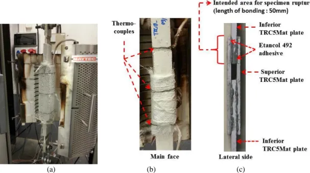
A thermomechanical machine, usually called the TM20kN-1200C machine, used for this study [VU 2013]. This machine has a loading sensor of 20 KN, a furnace that can provide a high temperature, potentially up to 1200°C. Figure 1a shows the furnace 1200C and the configuration of a high-temperature tensile test on a specimen TRC5Mat-dI protected by a thermal insulator. This machine is automatic and servo-controllable and can simultaneously generate the mechanical and thermal loadings. The maximum velocity of temperature rise in the oven is 30°C/ minute. Three thermocouples are then installed on the specimen at equal distances in the middle of the furnace in order to measure the temperature around the specimen (Figure 1b). The tests and validation of the measurement of the specimen, obtained by the laser sensor, are previously described [VU 2013].
2.1. Tested specimens
In this research, only the thermomechanical behaviour of the "TRC/adhesive" interface is studied because of the limited size of the used furnace (effective height of 30cm; effective diameter of 8cm, Figure 1a). In the following, the main components, the dimension of the tested specimen are respectively presented.
Textile-reinforced concrete
One textile-reinforced composite (called TRC5Mat) is manufactured with a sulfo-aluminate cementitious matrix and five layers of alkali resistant (AR) - MAT glass textile. The used sulfo-aluminate cementitious matrix is made with an ettringite binder, a granular skeleton (with a grain size below 30 µm), water and adjuvant agents (the tensile bending strength of this matrix at 28 days of age is 8.5 MPa, its compressive strength at 28 days of age is 35 MPa, and its other properties are presented in [MIC 2013, MIC 2012]. The reinforcement ratio of the textile for the TRC composite is 2.5% (Vf = fibre volume/ TRC volume = 2.5%). The used alkali resistant (AR) - MAT glass textile has an open geometry to allow easy penetration of the cement mortar. Table 1 Table 2 respectively present the physical and mechanical properties of a single fibre of the alkali-resistant glass, the alkali-resistant (AR)-MAT glass textile (commercially named "Cem-M601 MAT®"). The choices of the textiles are justified by a very good ability to bridge cracks, including at an early stage of mechanical stress of the MAT textile [NGUYEN 2015]. The sulfo-aluminate cementitious matrix and the reinforcement textiles are cast in a mold to obtain a rectangular plate of TRC5Mat (having the dimension 800mm x 500mm x 10mm). After 7 days, the rectangular plates were cut, resulting in specimens of 700 mm × 45 mm × 10 mm.
Tensile resistance (MPa) Elastic modulus (GPa) Strain at rupture (%) Softening point (°C) Poisson coefficient Thermal expansion coefficient Density (kg/dm3) 1000÷1700 74÷76 1.8 860 0,25 7.9. 10-6 2.6
Table 1: Physical and mechanical properties of a single fibre of the alkali-resistant glass
Fibre diameter Nominal weight Density Length of cut yarn
14 m 120 g/m2 2.68 g/cm3 ~ 75 mm
Table 2: Physical and mechanical properties of the alkali-resistant (AR)-MAT glass textile
Epoxy adhesive
The Etancol 492 glue, an epoxy resin type, is chosen to make the ‘‘TRC5Mat/adhesive’’ interface because it is commonly used in reality in order to bond composite to repair and/or strengthen the structures. The Etancol 492 glue is a structural adhesive based on epoxy resin (without solvent, with two components of cycloaliphatic hardeners). It adheres the requirements of EN 1504-4 standard as a structural bonding product for reinforcements by external bonding. Its mechanical characteristics at ambient temperature, given by the manufacturer of this glue (SPPM society), are shown in Table 3.
TRC5Mat-dI specimen (without fire protection)
The configuration of all of the TRC5Mat-dI specimens tested at high temperature in this study is presented in Figure 1a [NGUYEN 2015]. At the same moment with the bonding of TRC5Mat plates, four aluminum plates, with the dimensions of 3mm x 45mm x 70 mm, are glued on both ends of each TRC5Mat-dI specimen. The
TRC5Mat-dI specimens are then stored in the laboratory at least 7 days before the tensile/shear test so that the adhesive at the interface of these specimens reaches their resistance stability. The TRC5Mat-dI specimens are drilled at each end to be compatible with the used “ball joint” loading heads (Figure 1).
TRC5Mat-dI specimen (protected with fire protection material)
Two thermal insulators are used to protect the TRC5Mat-dI specimen. The first insulator, called PROMASPRAY®T, is a commercial product of the PROMAT company. It is a sprayed coating for the thermal insulation of surfaces that are not exposed to the inclemency of weather. This insulator is a dry material that consists of slag wool, hydraulic and semi-synthetic binders and various adjuvants. It is in the form of flakes. The second insulator, called the insulator A, was developed in the laboratory LGCIE [MIC 2013, MIC 2012]. Table 5 presents the list of the tests carried out on TRC5Mat-dI specimens (protected by the ‘‘PROMASPRAY®T’’ or insulator A). In order to observe the evolution of the temperature at the TRC5Mat/adhesive interface, the isolated specimen "TRC5Mat-dI-Insulator A-1.5cm-50%-2" is equipped with a thermocouple at this interface.
Designation Temperature of vitreous transition, Tg Implementation temperature Volumic mass Ultimate tensile stress Elongation at rupture Ultime shear stress Ultime compressive stress Characteristic 54 °C ± 2 °C + 5 °C / + 35 °C 1.5 ± 0.03 g/cm3 29.5 ± 1 MPa 0.65 ± 0,10 % > 15 MPa 83 ± 1,6 MPa
Standard ISO 11357-2 ISO 527 ISO 527 ISO 604
Table 3 : Some properties of the Etancol 492 glue
(a) (b) (c)
Figure 1. (a) Furnace 1200°C and specimen TRC5Mat-dI protected by a thermal insulator; (b) TRC5Mat-dI specimen image (without fire protection material); (c) Lateral side of the TRC5Mat-dI specimen.
2.2. Loading paths of thermomechanical tests
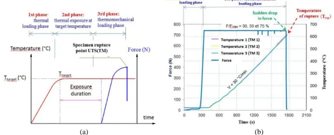
The regimes 1 and 2 are used for this study (Figure 2). In the regime 1 (Figure 2a), the temperature rises to desired one. Once the furnace temperature reaches the target value, it is then kept constant for one desired exposure duration. The force, applied to the specimen, increases until the maximum one that the specimen can be resisted. In the regime 2 (Figure 2b), the axial force, applied to the specimen, increases to desired value. The axial force increase is controlled by the traverse displacement with a displacement rate of 300µm/ minute. The desired axial force value (or the desired axial stress one) is maintained for the remainder of the test. The temperature rises to the maximum one (Trup) that the specimen can be resisted. At the end of the second phase of the test, there is a sudden drop in axial force that the specimen can support. The list of the tests carried on TRC5Mat-dI specimens according to the regimes 1 and 2 is presented on (Table 4). The test results of these tests are shown in the part 3.
(a) (b)
Figure 2 : Used loading paths : (a) regime 1: maximum mechanical strength holding at a constant temperature; (b) regime 2: maximum temperature holding at a target and constant stress.
Regime 1 Regime 2 Specimen reference Target temperature (°C) Exposure duration at target temperature Numb er of tests Specimen reference σtarget/σmax (%) σtarget (MPa) Number of tests TRC5Mat-dI- T20-r1 (1,2) (*) 20 - 2 TRC5Mat-dI- T20-r1 (1,2) (*) 100 5.24 2 TRC5Mat-dI-T100 (1) 100 30 minutes 1 TRC5Mat-dI-r0,3 (1,2) 30 3.93 2 TRC5Mat-dI-T200 (1,2) 200 30 minutes 1 TRC5Mat-dI-r0,5 (1,2) 50 2.62 3 TRC5Mat-dI-T300 300 30 minutes 1 TRC5Mat-dI-r0,75 (1,2,3) 75 1.57 3 TRC5Mat-dI-T400 400 30 minutes 1
Table 4 : List of the tests carried on TRC5Mat-dI specimens (without fire protection); (*) Two TRC5Mat-dI- T20-r1 (1,2) specimens : tested at 20°C and exploited as the tests conducted according to the regimes 1 and 2.
TRC5Mat-dI specimen (with fire protection) Thermal insulator /max (%) Thickness of the thermal insulator (cm) Number of tests TRC5Mat-dI-SprayT-1.5cm-50%-1 SprayT 50% 1,5 cm 2 TRC5Mat-dI-SprayT-1.5cm-50%-2 1,5 cm
TRC5Mat-dI-Thermal insulator
A-1.5cm-50%-1 Thermal
insulator A 50%
1,5 cm
2 TRC5Mat-dI-Thermal insulator
A-1.5cm-50%-2
1,5 cm
Table 5 : List of the tests carried out on isolated TRC5Mat-dI specimens according to the regime 2.
3. Test results
3.1. Behaviour of TRC5Mat-dI specimens
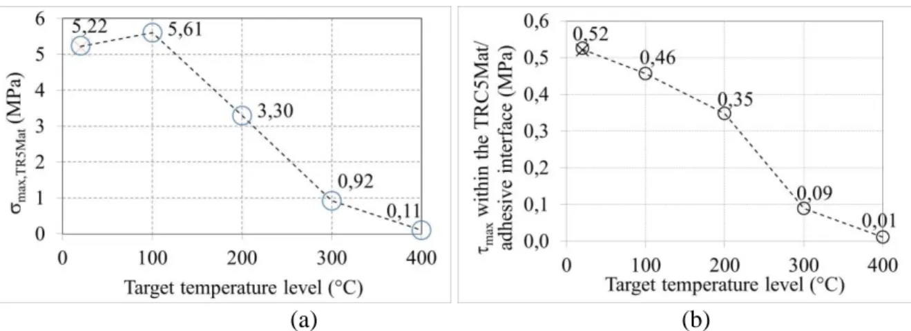
Figure 3a,b show the results of tests carried out according to the regime 1 on TRC5Mat-dI specimens. The observations after the tests show that the rupture of TRC5Mat-dI specimens happens to one of the two inferior TRC5Mat plates. This indicates that during the tests at various target temperature levels on the TRC5Mat-dI specimen, the maximum tensile strength of the TRC5Mat composite reaches before that the shear stress at the “TRC5Mat/ adhesive” interface reaches its maximum value. Results of these tests are presented in Figure 3a in terms of the ultimate stress at rupture of the TRC5Mat inferior plate as a function of the temperature. Figure 3b presents the results of these tests in terms of the mean shear stress of the TRC5Mat-dI specimen as a function of
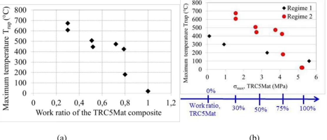
target temperature levels. This figure shows that the mean shear stress of the “TRC5Mat/adhesive” interface at 20°C (0,525 MPa) is much less than the ultimate shear stress of the epoxy adhesive (>15MPa, see the Table 3). It is also observed on the Figure 3 that the ‘‘TRC5Mat/adhesive/ TRC5Mat’’ interface is able to resist up to 400°C. Moreover, one can observe on the Figure 5a that the Etalcol492 epoxy adhesive becomes softening when the target temperature level is higher than 103°C. The results of the tests carried out on the TRC5Mat-dI specimen (Figure 3a,b) highlight that the two superior TRC5Mat plates, installed in the middle of the TRC5Mat-dI specimen thanks to the Etancol 492 epoxy adhesive (see Figure 1b,c), are good heat shields for the two “TRC5Mat/adhesive” symmetrical interfaces of the TRC5Mat-dI specimen. Both the TRC5Mat superior plates (total thickness of about 16 mm) allowed so slowing down the degradation of the epoxy adhesive characteristics under high temperature effect. Figure 4a shows results of the tests carried out, with the regime 2, on the TRC5Mat-dI specimens in terms of the obtained maximum temperature as a function of the (target/max) ratio value. This ratio can represent different service states that concerns mechanical stress of the studied TRC5Mat material. This figure shows that when the ratio (target/max) is equal to 0,3, the TRC5Mat-dI specimen can resist up to 680°C (or during a period of 23 minutes with a rate of temperature rise of 30°C/ minute). This result is remarkable because the Etancol 492 epoxy adhesive becomes softening when the target temperature levels is higher than 103°C (Figure 5a). This indicates that the TRC5Mat is able to mechanically and thermally resist.
(a) (b)
Figure 3. Results of tests carried out according to the regime 1 on TRC5Mat-dI specimens: (a) evolution of ultimate axial stress of the inferior TRC5Mat plate (max, TRC5Mat) and (b) evolution of mean shear stress
(max) within the “TRC5Mat/ E492 adhesive” interface as a function of target temperature levels.
Figure 4a,b show a comparison of results of tests carried out on TRC5Mat-dI specimens according to the regimes 1 and 2. This figure highlights the relationship between the external temperature around the TRC5Mat-dI specimen and the axial stress within the TRC5Mat inferior plate at its rupture moment. Note that in the tests performed according to the regime 1 (Figure 2a), during the second phase of the test (thermal exposure at target temperature), the samples are maintained at the target temperature for 30 minutes, the temperature state within the TRC5Mat plates of the TRC5Mat-dI specimen is almost homogeneous [NGUYEN 2015]. Furthermore, in the tests performed according to the regime 2 (Figure 2b), during the second phase of the test (thermomechanical loading phase), the external temperature of the TRC5Mat-dI specimen quickly increases with the rate of 30°C/ minute (or 0,5°C/second) up to the maximum external temperature that the specimen can support. With such quick increase rate of the external temperature around the TRC5Mat-dI specimen, temperature levels are not uniform within elements of this specimen. In the tests carried out according to the regime 2, temperature levels of elements of the TRC5Mat-dI specimen near heating sources are more important than those in the middle of this specimen. The Figure 4 shows that for a same axial tensile stress level within the TRC5Mat inferior plate of the TRC5Mat-dI specimen, the maximum level of the external temperature around this specimen, reached during the test according to the regime 2, is significantly greater than that achieved during the test carried out under the regime 1. These results show that when a TRC5Mat-dI specimen is tested according to the regime 2, the maximum external temperature with which the specimen can withstand significantly depends on rate of the external temperature rise and on specimen configuration. The results of tests are carried out on isolated TRC-dI specimens are summarized in Table 6. These tests show that a thermal insulation with 1,5cm thickness allows extending of more than 500°C of the temperature at rupture (higher than 1000°C) for the joint carrying a work ratio of 50%. Furthermore, Figure 5b shows the relationship between the rise of the external temperature of the joint protected by a thermal insulation and the rise of the internal temperature within the TRC/adhesive interface. This figure indicates that when the maximum internal temperature within the TRC/epoxy adhesive interface reaches 230°C, the isolated joint is broken. These results have shown the real thermal efficiency of the TRC
composite and of the thermal insulation material. They have also highlighted that the TRC is a performance material in terms of mechanical and thermal resistance.
(a) (b)
Figure 4. (a) Evolution of the maximum external temperature around of the TRC5Mat-dI specimen (regime 2) as a function of the work ratios of the TRC5Mat inferior plates; (b) Relationship between the external temperature around the TRC5Mat-dI specimen (regimes 1 and 2) and maximum axial stress of the TRC5Mat inferior plates.
(a) (b)
Figure 5. (a) Evolution of the ultimate axial stress of the Etancol 492 epoxy as a function of target temperature levels [NGUYEN 2015]; (b) Evolution of the external temperature of the specimen (Text) and the temperature at
the TRC5Mat/adhesive interface (Tint) (for the TRC5Mat-dI-Thermal insulator A-1.5cm-50%-2 specimen).
TRC5Mat-dI specimen (with fire protection) Velocity of temperature
rise (°C/minute) /max (%) Temperature at rupture (°C) TRC5Mat-dI-SprayT-1.5cm-50%-1 30 50 >972 TRC5Mat-dI-SprayT-1.5cm-50%-2 28 50 >996
TRC5Mat-dI-Thermal insulator A-1.5cm-50%-1 30 50 >1000
TRC5Mat-dI-Thermal insulator A-1.5cm-50%-2 29 50 >1000
Table 6. Summary of the results of tests carried out on the isolated TRC5Mat-dI specimen
4. Failure modes
Figure 6 shows failure modes of TRC5Mat-dI specimens that are tested according to the regimes 1 and 2. This figure indicates that for the maximum external temperature around the TRC5Mat-dI specimen ranging from 20°C to 300°C, the failure of the specimen takes place in TRC5Mat inferior plates (mode A). For external temperature level of 400°C (and after a thermal exposure at this temperature of 30 minutes for the regime 1), the failure of the specimen occurs at the TRC5Mat/adhesive interface (interfacial failure, mode B). For the external temperature around the TRC5Mat-dI specimen ranging from 400°C to 500°C (associated with a rate of temperature rise of 30°C/ minute for the regime 2), the majority of the specimens exhibit a mixed failure combining both the mode A (in the TRC5Mat inferior plate) and B (within the TRC5Mat/ adhesive interface).
For the maximum external temperature around the TRC5Mat-dI specimen higher than 600°C (associated with a rate of temperature rise of 30°C/ minute for the regime 2), the rupture of the TRC5Mat-dI specimen takes place at the «TRC5Mat/adhesive» interface (failure mode B). This failure mode is followed with a complete decomposition of the epoxy adhesive. Figure 6 clearly shows an inverse relationship between the mechanical loading level (or the work ratio target/max of the TRC5Mat) and the rupture temperature of specimen. As expected, it can be seen that when the specimens are subjected to low mechanical work ratio, they lose their structural integrity at higher temperatures. This clearly suggests the influence of thermal and mechanical interactions on the behaviour of the TRC5Mat-dI specimens. The failure modes of TRC5Mat-dI specimen protected by the PROMASPAY@T insulator and the thermal insulator A are presented in Figure 7. All of the tested specimens exhibit a rupture at the TRC5Mat/adhesive interface (interfacial failure, mode B) (Figure 7).
Figure 6. Failure modes of TRC5Mat-dI specimen tested according to the regimes 1 and 2
Figure 7. Failure modes of TRC5Mat-dI specimen protected by PROMASPAY@T and the insulator A
5. Conclusion
This paper presents an experimental investigation on thermomechanical behaviour at high temperature of the textile reinforced concrete (TRC)/epoxy adhesive interface (without or with fire protection). The specimen having two symmetrical TRC5Mat/adhesive interfaces, called TRC5Mat-dI specimen or TRC5Mat-dI joint, is designed for this study. The TRC5Mat composite is made with a sulfo-aluminate cementitious matrix and five layers of alkali resistant (AR) - MAT glass textile. An epoxy adhesive (Etancol 492) is used for this study. Thermomechanical tests have been carried out, according to two thermomechanical loading paths, on TRC5Mat-dI. The evolution of ultimate axial stress of the TRC5Mat inferior plate and the evolution of mean shear stress within the “TRC5Mat/epoxy adhesive” interface as a function of target temperature levels have been experimentally identified. The relationship between external temperature around the TRC5Mat-dI specimen, according to the regimes 1 and 2, and maximum axial stress of the TRC5Mat composite inferior plates are also discussed. The results of these tests show that when a TRC5Mat-dI specimen is tested according to the regime 2, the maximum external temperature with which the TRC5Mat-dI specimen can withstand significantly depends on rate of the external temperature rise and on specimen configuration. When the work ratio of the studied TRC evolves from 1 to 0,3, with increase rate of external temperature of 0,5°C/second, the maximum external temperature level around the TRC5Mat-dI specimen evolves from 25°C to 680°C. The failure modes of the TRC5Mat-dI joints, according to two thermomechanical loading paths, are also analyzed. For the external temperature around the TRC5Mat-dI specimen ranging from 20°C to 300°C, the failure of the specimen takes
place in TRC5Mat composite inferior plates (failure mode A). For the target temperature level of 400°C (tested at the regime 1), the failure of the specimen occurs at the TRC5Mat/adhesive interface (interfacial failure, failure mode B). This study clearly shows an inverse relationship between the mechanical loading level (or work ratio
target/max of the TRC5Mat) and the rupture temperature of specimen. It can be seen that when the specimens
are subjected to low mechanical work ratio, they lose their structural integrity at higher temperatures. This clearly suggests the influence of thermal and mechanical interactions on the behaviour of the TRC5Mat-dI specimens. In addition, the thermomechanical tests have been also carried out on the “TRC/epoxy adhesive/TRC” joint, protected by thermal insulation materials (or fire protection ones). These tests show that a thermal insulation with 1,5 cm thickness allows extending of more than 500°C of the temperature at rupture (higher than 1000°C) for the joint carrying a work ratio of 50%. The failure mode generally observed for the isolated joints is the interfacial failure. These results have shown the real thermal efficiency of the TRC composite and of the thermal insulation material. They have also indicated that the TRC composite is a performance material in terms of mechanical and thermal resistance.
6. Acknowledgment
This research was supported by the LMC2 laboratory for the experimental work. This research has also been realized with the financial support of a doctoral scholarship from the Ministry of Education and Training of Vietnam. We would like to thank the team of technicians of the Civil Engineering Department of the IUT Lyon 1, University Lyon 1 for their technical support.
7. Bibliography
[BUTL 2010] BUTLER M, LIEBOLDT M, MECHTCHERINE V. "Application of textile-reinforced concrete (TRC) for structural strengthening and in prefabrication". Ad. in cement-based materials. Taylor & FrancisGr 127–36; 2010. [CAM 2007] CAMATA G., PASQUINI F., SPACONE E. "High temperature flexural strengthening with externally bonded
FRP reinforcement'', 8th Int. Symp. on Fiber Reinforced Polymer Reinf. for Concrete Structures, FRPRCS-8; 2007. [CON 2014] CONTAMINE R., JUNES A., SI LARBI A. “Tensile and in-plane shear behaviour of textile reinforced
concrete: analysis of a new multiscale reinforcement”, Const. and Build. Materials, 51, 2014, 405-413; 2014.
[COL 2015] COLOMBO I.G., COLOMBO M., DI PRISCO M., 2015. Bending behaviour of Textile Reinforced Concrete sandwich beams, Construction and Building Materials, Volume 95, Pages 675-685
[FER 2012] FERRIER E., MICHEL L., SI LARBI A. "Comportement mécanique en cisaillement des interfaces composite/béton aux faibles (-40°C) et hautes températures (+80°C)'', in XXe RUGC Chambéry (in French); 2012. [KLA 2008] KLAMER E., HORDIJK D., HERMES M. 2008. "The influence of temperature on RC beams strengthened with
externally bonded CFRP reinforcement'', Heron, vol. 53 (3), p. 157–185.
[LEO 2009] LEONE M., MATTHYS S., AIELLO M. A., 2009. "Effect of elevated service temperature on bond between FRP EBR systems and concrete", Composites Part B: Engineering, vol. 40, no. 1, pp. 85-93.
[GAM 2006] GAMAGE J., AL-MAHAIDI R., WONG M. "Bond characteristics of CFRP plated concrete members under elevated temperatures", Composite Structures, vol. 75, no. 14, pp. 199-205; 2006.
[HEG 2008] HEGGER J., VOSS S. 2008. "Investigations on the bearing behaviour and application potential of textile reinforced concrete'', Engineering Structures , vol. 30, no. 7, pp. 2050-2056.
[NGUYEN 2015] NGUYEN T. H. Contribution à l’étude du comportement thermomécanique à très haute température des matériaux composites pour la réparation et/ou le renforcement des structures de Génie Civil. Ph.D. dissertation [in French] of the University Claude Bernard Lyon 1; 2015.
[VU 2013] VU X.H., JUNES A., SI LARBI A., HAMELIN P. Caractérisation expérimentale des propriétés thermo-mécaniques à haute température du mortier renforcé de textile (TRC). 9p, in French. Procceding of International Conference CIGOS2013 : construction and sustainable development. Lyon, France; 2013.
[CON 2011] CONTAMINE R., SI LARBI A., HAMELIN P., 2011. Contribution to direct tensile testing of textile reinforced concrete (TRC) composites. Construction and Building Materials 2010; 24: 1928-1936; 2013.
[MIC 2013] MICHEL M., AMBROISE J. 2013. Développement de composites à matrice minérale et à renfort textile. 31ème Rencontres universitaires de l'AUGC. [in French].
[MIC 2012] MICHEL M., GEORGIN J.-F., AMBROISE J. Improving the mechanical performance of high-grade slag cement by the addition of Portland cement and sulfoaluminate cement. Const. and Buil. Materials 37 (2012) p.291–300.