DOI: 10.1007/s00339-003-2349-4 Materials Science & Processing g. dumitru1,u v. romano1 y. gerbig2 h.p. weber1 h. haefke2
Femtosecond laser processing of nitride-based
thin films to improve their tribological
performance
1University of Bern, Institute of Applied Physics, Sidlerstrasse 5, 3012 Bern, Switzerland
2CSEM Swiss Center for Electronics and Microtechnology Inc., Jaquet Droz 1, 2007 Neuchâtel, Switzerland
Received: 6 June 2003/Accepted: 14 August 2003
Published online: 9 October 2003 • © Springer-Verlag 2003 ABSTRACT The ability of femtosecond laser pulses to pat-tern coated tribological surfaces in order to improve their wear behavior was investigated. Experiments were performed with a Ti: sapphire laser (wavelength: 800 nm, energy density: 2 J/cm2, pulse duration: 100 fs) on TiN- and on TiCN-coated surfaces. Morphological analyses of the laser-treated surfaces were carried out and did not reveal any film delamination or other coating damage after laser processing. Tribological tests simulating rapidly increasing contact pressures under boundary friction were performed on both unpatterned and laser-patterned coated surfaces using a steel counter body. The patterned sur-faces showed significantly better tribological performance with respect to stability and the value of the friction coefficient during testing. EDX analyses of the tested unpatterned sam-ples revealed complete coating removal and material transfer from the counter body to the sample surface. In the case of the laser-patterned surfaces, only slight coating damage and an accumulation of debris from the steel counter body in the laser-induced pores were observed.
PACS42.62.Cf; 81.40.Wx
1 Introduction
Laser micropatterning of functional surfaces using nanosecond pulses has been demonstrated [1–6] to improve their tribological performance, leading to increased lifetimes of the tribological systems in which they are used. Arrays of pores obtained by laser micromachining can act as lubri-cant reservoirs, capable of feeding the lubrilubri-cant directly into the contact zone of the sliding surfaces. Another important function of the pores is to trap wear particles and to remove them from the tribocontact area. Furthermore, the laser pat-terning of surfaces can promote the occurrence of hydrostatic or hydrodynamic lubrication conditions [7]. Mainly depend-ing on application-related conditions (for example, contact pressure, sliding velocity, and oil viscosity), the effects of one of the aforementioned mechanisms may prevail; however all of them contribute to improving the tribological properties of laser-patterned surfaces.
u Fax: +41-31/631-8940, E-mail: [email protected]
Reducing the surface wear through laser micropatterning is a technique of great potential, but it is still in the devel-opment phase. A well-established method for minimizing the occurrence of debris particles is the coating of sliding surfaces with wear-resistant thin films (for example, nitride-based ce-ramic coatings [8]). A further gain in surface functionality has been recently demonstrated by combining laser micropattern-ing and coatmicropattern-ing techniques [9]: laser-patterned TiCN-coated surfaces, which were obtained through ns-laser micromachin-ing of WC-Co followed by TiCN coatmicromachin-ing through CVD have shown notably increased (by a factor of 15) lifetimes.
This indirect approach (laser patterning followed by coat-ing) involves mechanical post-processing after ns-laser ma-chining and also gives rise to potential problems related to film adhesion to the layer of laser-modified material. The overcoming of these drawbacks using fs laser pulses and the results of the first tribological tests performed on fs-laser-patterned coated surfaces are the main topics of this work. 2 Laser patterning
2.1 General considerations
Laser patterning can be applied to various mat-ing surfaces in a large number of systems, such as magnetic hard disks [10], forming tools [11], and automotive compo-nents [12]. However, due to the variety of operating conditions and the specific technical requirements to be met, optimal structures (that is, pore diameters and depths, and pattern densities) must be found for each class of application. For instance, intense work has been carried out in the field of mechanical seals and piston/cylinder systems operating in hydrodynamic lubricating conditions [12–14], for which an optimum for the geometry of the laser-induced patterns has been found.
Previous investigations [3, 15] under mixed lubrication conditions have indicated that suitable pore diameters should be smaller than 50µm with aspect ratios between 1 : 2 and 1 : 1. Comparing these values with typical film thicknesses, pore depths are in most cases larger than film thicknesses. There-fore, a direct laser-processing procedure includes the com-plete penetration of the protection coating (without inducing collateral damage) and a further drilling into the substrate.
The use of ns laser pulses has been found to be unsuit-able for direct processing. The size of the thermally affected
zone is of the same order of magnitude as the film thickness, which may lead to film cracks. Experiments performed with a Q-switched Nd: YAG laser (1.06 µm, 100 ns) have shown unsatisfactory results in the case of dielectric and nitride-based coatings [16]. Passing from ns to fs laser pulses has been demonstrated to improve the quality of microprocess-ing [17–20] of ceramic films, due to the fact that unwanted thermal diffusion is drastically reduced.
In the case of fs-laser processing, the absorption of the energy needed for material ablation is highly confined to a su-perficial layer and occurs via different material-specific phe-nomena in practically all materials. This makes possible the processing of both the protective film and substrate using the same laser beam. Based on these considerations and on pre-vious studies [18] regarding fs-laser ablation properties of ultra-hard coatings and substrates, the fs-laser patterning of coated tribological surfaces was considered to show potential and was undertaken.
2.2 Experiments
Surface-patterning experiments were carried out in air using the beam from a Ti: sapphire laser delivering 100 fs pulses. The laser beam was attenuated and then focused, in order to obtain pore diameters of approximately 30µm at an incident laser fluence of 2 J/cm2(maximal fluence, Gaussian beam profile). The target materials were TiN-coated stain-less steel (AISI 440C) and TiCN-coated hard metal (WC-10 Co). The TiN coatings were obtained through physical vapor deposition (magnetron sputtering) and the TiCN films through chemical vapor deposition. The film thicknesses were 1 and 3.5–4 µm, respectively. On each specimen, a surface of 8× 8 mm2 zones was patterned, whereas the spatial period
of the laser-induced pore arrays was 80µm. On each ir-radiation spot, 100 incident pulses were used, which led to crater depths of approximately 18µm in the TiN-coated steel and of 15µm in the TiCN-coated hard metal. At the laser repetition rate of 1 kHz and for the aforementioned pattern parameters, 25–30 minutes were needed to pattern such an 8× 8 mm2zone.
3 Morphology of laser-induced structures
In order to examine the features of the laser-induced structures and the occurrence of collateral damage (cracks and film delamination), the laser-treated surfaces were analyzed using optical microscopy, scanning electron mi-croscopy (SEM), and atomic force mimi-croscopy (AFM); an accurate volume representation of induced cavities was ob-tained using a replica technique.
The optical microscopy investigations of the crater bound-ary zone, where damage due to laser treatment was apt to appear, did not reveal (Fig. 1) any film cracks, delamination, or other surface modifications. These analyses also showed that the remaining surfaces were not affected by the laser treatment; their roughness values did not change and they could be used as tribological surfaces directly after the fs-laser processing.
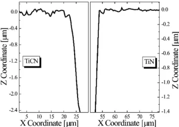
AFM analyses (Fig. 2) demonstrated a distinct transition between irradiated and non-irradiated film zones, without sig-nificant rims at the crater borders. Regarding the transition
FIGURE 1 Images (optical microscopy) of pores induced in ceramic films (100× 2 J/cm2)
FIGURE 2 AFM profiles along diameters of pores shown in Fig. 1
zone between the coating and substrate in the case of TiN, (1µm thick) smooth pore walls, without any spikes or sharp rims, were noticed. In the case of TiCN, no such points were observed, but in this situation, the film thickness (3.5–4 µm) was outside the reliability zone for AFM-measured depths.
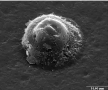
To investigate the actual 3D shape of the laser-induced pores, a replica technique [1] was used to achieve a “nega-tive copy” from microcraters; an SEM image from a replica of a single pore is shown in Fig. 3. Similar shapes were also ob-tained for pores in the TiN film. Therefore, one can state that the slope change that is noticeable in Fig. 3 is related to laser irradiation factors.
4 Tribological testing
4.1 Experiments
In order to confirm the beneficial effects of laser patterning on the tribological performance of coated sur-faces, reciprocating sliding tests were performed on a linear-oscillation tribometer (SRVtest system). In these tests a cylinder (counter body) was slid with a frequency of 10 Hz and a stroke of 2 mm on the tested sample, which was inserted into a lubricant-containing recipient. The counter body was made of low-carbon steel (hardness 110 HV, tensile strength
FIGURE 3 Volume representation of a laser-induced pore (TiCN-coated hard metal, 100× 2 J/cm2)
350 N/mm2). The lubricous fluid (additivated mineral oil)
covered the sample surface fully (flood lubrication). During the first 30 s, the load was linearly increased to raise the con-tact pressure from 20 to 250 N/mm2, which is comparable
to the pressures that occur in metal-forming processes [7]. Afterwards, the load was kept constant until the end of the test. The evolution of the friction coefficient (average over one cycle) was continuously recorded during the test. The recording was automatically stopped if the friction coefficient reached values aboveµ > 0.45, which corresponds to friction values in the unlubricated system, or if a pre-defined time of 30 minwas reached. Prior to testing, the counter body and test sample were cleaned in acetone in an ultrasonic bath and dried with compressed air.
4.2 Frictional behavior
Typical friction curves for unpatterned and laser-patterned surfaces are depicted in Fig. 4. Significant dif-ferences in the friction evolution between the two types of surfaces can be seen. Due to insufficient lubrication of the tribocontact area, the unpatterned surfaces exhibited a con-tinuously increasing friction coefficient that attained the
FIGURE 5 SEM images of wear tracks on TiN-coated surfaces: a unpatterned and b patterned
FIGURE 4 Friction curves for laser-patterned and unpatterned TiN-coated surfaces
friction-related stop criterion shortly after the start of the test (100–120 s). In the case of the patterned surfaces, the fric-tion coefficient rose temporarily to values ofµ ∼ 0.2 in the running-in phase of the tests, but decreased afterwards and re-mained stable at a level ofµ ∼ 0.11 until the end of the test; this value is typical for boundary friction [21].
4.3 Morphological analyses on tested surfaces
After tribological testing, SEM and energy disper-sive X-ray (EDX) investigations were carried out to study the wear tracks generated on the tested surfaces. Representative close-ups of the worn surface regions on the unpatterned and laser-patterned samples are shown in Fig. 5.
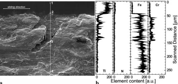
To determine the exact nature of the stripe-shaped wear features observed on the unpatterned TiN surface, EDX line scans were performed (Fig. 6). The presence of the chemical elements Fe, Cr, and Ti was proven along a line running from a less worn region to a damaged zone (Ti: protective film, Cr: substrate of coated sample, Fe: substrate of coated sample and counter body).
Along the EDX line scan from points 1 to 4 in Fig. 6, the following features are observed: (i) the Ti content re-mains constant (150 counts/s) between points 1 and 2; at point 2, the content drops suddenly down to 0 and remains at this value until point 4 is reached; (ii) the Cr
concentra-FIGURE 6 Detail from a wear track on a TiN-coated and unpatterned surface: a SEM image and b EDX analysis of elemental content along the white line marked in a
tion is 0 between points 1 and 2; at point 2, the concen-tration increases to about 40 counts/s and oscillates around this value until point 3 is passed; between points 3 and 4, the Cr concentration decreases to zero; (iii) there is no de-tectable Fe signal between points 1 and 2; at point 2, an Fe signal appears suddenly and rises from 150 to 200 counts/s at point 4.
If one considers that the substrate of the coated disk is steel with a high Cr content, but that the counter body is made of non-alloyed steel, an interpretation of these results is that a large number of solid–solid contacts were generated be-tween the sample and counter body, which led to damage and finally to local removal of the coating from the substrate. The contact between the exposed steel substrate (uncoated sam-ple) and the steel counter body sustains excessive material transfer from the counter body to the sample due to adhesive wear processes.
In the case of the laser-patterned surfaces, only slight wear features were noticeable. Noteworthy is the fact that a large part of the pores situated in the wear track were filled to
FIGURE 7 Detail from a wear track on a TiN-coated and laser-patterned surface: a SEM image of a filled pore and b–d EDX mappings for various elements
varying degrees with debris. An SEM image of an almost completely filled pore and its vicinity is shown in Fig. 7. The spatial distribution of the chemical elements Ti, N, and Fe (Ti, N: protective film, Fe: counter body) in the depicted zone was determined through EDX mapping, with a lateral resolution of 0.2 µm. The number of counts indicating the presence of a certain element was converted into gray levels and distribu-tion maps were constructed; they are also depicted in Fig. 7. From these images, one can see the uniform and continuous presence of Ti and N in the pore surroundings and the almost complete absence of Fe from this zone. On the other hand, inside the pore a quasi-total absence of Ti and N and a large Feamount were detected. These results indicate an unbroken TiNfilm in the pore surroundings and a large accumulation of debris coming from the counter body in the laser-induced microcraters.
5 Conclusions
The direct laser processing of TiN- and TiCN-coated tribological surfaces using femtosecond pulses was demonstrated. Investigations related to the morphology of the laser-induced pores indicated no significant roughness in-creases, no delamination of the treated films from their sub-strates, and no sharp points or discontinuities on the pore walls at the coating–substrate interfaces.
Unpatterned and laser-patterned coated surfaces were tested in lubricated reciprocating sliding tests to compare their tribological performance. For boundary lubrication and rapidly increasing contact pressures, the laser-patterned sur-faces maintained a low and stable friction in the system over a significant longer duration (> 15 times) than the unpatterned ones.
Analyses performed on the tribologically tested unpat-terned surfaces showed significant damage, such as complete coating removal and deposits of material from the counter body on the sample surface in large regions of the former contact zone. Nevertheless, still intact protective films and de-bris accumulation from the counter body in the laser-induced
microcraters were observed in the case of the tribologically tested laser-patterned surfaces.
These observations lead to the conclusions that the laser patterning (i) improves the lubrication of the interface, which enhances the efficiency of the coating due to less wear through minimized solid–solid contacts and (ii) prohibits debris-induced wear processes through the trapping of generated particles in the microcraters.
ACKNOWLEDGEMENTS The authors gratefully acknowledge the contributions of Dr.J. Hermann and Mr.S. Bruneau to the fs experiments and the help of Mrs.E.Kr¨ahenb¨uhl in the surface analyses.
REFERENCES
1 G. Dumitru, V. Romano, H.P. Weber, H. Haefke, Y. Gerbig, E. Pflüger: Appl. Phys. A 70, 485 (2000)
2 H. Haefke, Y. Gerbig, G. Dumitru, V. Romano: Proc. Int. Trib. Conf. in Nagasaki, Japan, 2000, p. 217
3 Y. Gerbig, G. Dumitru, V. Romano, V. Spassov, H. Haefke: Proc. MRS Symp. in Boston, USA, Fall 2002 Vol. 750, Y5.37.1 (2003)
4 U. Popp, T. Neudecker, U. Engel, M. Geiger: Proc. 2nd Int. Conf. THE, Coatings in Manufacturing Engineering in Hannover, Germany, 2001, T3–1
5 A. Volchok, G. Halperin, I. Etsion: Wear 253, 509 (2002) 6 X. Wang, K. Kato, K. Adachi, K. Aizawa: Trib. Int. 36, 189 (2003) 7 J. Bech, N. Bay, M. Erkisen: Wear 232, 134 (1999)
8 G.S. Upadhyaya: Sintered Metallic and Ceramic Materials (John Wiley, New York 2000)
9 G. Dumitru, V. Romano, H.P. Weber, H. Haefke, Y. Gerbig: Proc. WLT, Laser 2001, pp. 351
10 L. Zhou, K. Kato, N. Umehara, Y. Miyake: Trib. Int. 33, 665 (2000) 11 T. Neudecker, U. Popp, T. Schraml, U. Engel, M. Geiger: Proc. 6th ICTP,
Advanced Technology of Plasticity, 1999, Vol. 3, pp. 2175–2180 12 G. Ryk, Y. Kligerman, I. Etsion: Trib. Trans. 45, 444 (2002) 13 I. Estion, Y. Kligerman, G. Halperin: Trib. Trans. 42, 511 (1999) 14 A. Ronen, I. Etsion, Y. Kligerman: Trib. Trans. 44, 359 (2001) 15 G. Dumitru, V. Romano, H.P. Weber, H. Haefke, Y. Gerbig: Proc. SPIE
4157, 105 (2001)
16 T. Kononenko, S. Garnov, S. Pimenov, V. Konov, V. Romano, B. Borsos, H.P. Weber: Appl. Phys. A 71, 627 (2000)
17 S. Nolte, C. Momma, H. Jacobs, A. Tünnermann, B. Chichkov, B. Wellegehausen, H. Welling: J. Opt. Soc. Am. B 14, 2716 (1997) 18 G. Dumitru, V. Romano, H.P. Weber, M. Sentis, W. Marine: Appl. Phys.
A 74, 729 (2002)
19 J. Bonse, H. Sturm, D. Schmidt, W. Kautek: Appl. Phys. A 71, 657 (2000)
20 Y. Hirayama, M. Obara: Appl. Surf. Sci. 197–198, 741 (2002) 21 T. Mang, W. Diesel: Lubricants and Lubrication (Wiley-VCH,