Design and Development of an Affordable
Autonomous Vehicle for Bike Lanes
by
Abhishek Agarwal
Bachelor of Technology in Mechanical Engineering National Institute of Technology Durgapur (2010) Submitted to the Department of Mechanical Engineering in partial fulfillment of the requirements for the degree of
Master of Science in Mechanical Engineering at the
MASSACHUSETTS INSTITUTE OF TECHNOLOGY
June 2018
@
Massachusetts Institute of Technology 2018.A uthor ...
Certified by...
Certified by..
Accepted by .
All rights reserved.
Signature redacted
partment of Mechanical Engineering MwY'21, 2018...
Signature redacted
Sertac Karaman
Associate Professor of Aeronautics and Astronautics
Thesis Supervisor
...
Signature redacted
Albertr1odriguez
Assistant Professor of Mechanical Engineering
Mechanical Engineering Faculty Thesis Reader
...
Signature re
Rohan Abeyaratne
Chairman, Department Committee on Graduate Theses
MAAMUS"MS INSTITUTE OF TECHNOLOGY co
JUN 2
52018
acted
Design and Development of an Affordable Autonomous
Vehicle for Bike Lanes
by
Abhishek Agarwal
Submitted to the Department of Mechanical Engineering on May 21, 2018, in partial fulfillment of the
requirements for the degree of
Master of Science in Mechanical Engineering
Abstract
The last three decades have seen steadily increasing research efforts, both in academia and in industry, towards developing driverless vehicle technology. Autonomous ve-hicles have the potential to dramatically reduce the contribution of driver error and negligence as the cause of vehicle collisions. They will also provide a means of per-sonal mobility to people who are unable to drive due to physical or visual disability. They will also become a major component of smart urban infrastructure by reducing traffic congestion and providing last-mile connectivity.
However, most of the development is largely focused on four-wheeled vehicles with expensive sensors and onboard computing. Also, these vehicles have to meet strict safety standards and regulations for operation in a hostile environment like car lanes in dense cities.
This thesis presents the design and development of the Persuasive Electric Vehicle (PEV), a low-cost autonomous electric tricycle specifically designed for operation in bike lanes in urban environments. We adopt a ground-up approach towards building an autonomous vehicle which operates in less hostile traffic conditions as compared to car lanes. The vehicle uses comparatively low-cost sensors and onboard compute system for achieving the task of autonomy. We also demonstrate the efficacy of multi-sensor fusion for state estimation as well as the implementation of a SLAM software for 2D mapping of an urban environment.
Thesis Supervisor: Sertac Karaman
Title: Associate Professor of Aeronautics and Astronautics
Mechanical Engineering Faculty Thesis Reader: Alberto Rodriguez Title: Assistant Professor of Mechanical Engineering
Acknowledgments
First and foremost I have to acknowledge the support of my advisor Prof. Sertac Karaman. As a member of the Mechanical Engineering Department at MIT, my first year of study was colored by a frantic search for both an advisor and a project that appropriately suited my interests. Just as time was running out, Prof. Karaman offered me funding on an ideal project that turned into the basis for this work. Had Prof. Karaman not been so kind as to fund me at that time, I would not have remained at MIT nor would I have been able to complete my degree program. I cannot thank him enough for his unending support through my journey in this program including his generosity towards helping me get an extension each time. It is for this reason that I am eternally grateful to Prof. Karaman.
I would also like to thank Prof. Kent Larson from the MIT Media Lab for giving
me the opportunity to explore the project in multiple directions. Moreover, Prof. Larson was always encouraging and his positive attitude helped mitigate the stresses of several stakeholder demonstrations carried out during the length of this project.
It would be remiss to not thank Prof. Rohan Abeyaratne and Leslie Regan who showed great patience and support through the innumerable extensions I needed to finish this work. I would also like to thank Prof. Alberto Rodriguez for being my thesis reader from Mechanical Engineering Department.
I also owe a great debt of gratitude to Michael Lin for being a constant companion
and colleague throughout the project, as well as a great friend and confidant.
Lastly on this side of the pond, I would like to thank my roommates and friends who became wonderful companions on this two-year journey of research, classes, per-sonal development and life in general.
Finally, I would like to thank the three most important people in my life: My mother Menu Agarwal, my sister Mansi Agarwal and my fiance Sonal Katware for their unwavering support and understanding through some of the toughest phases of our lives during the period of this program. It would not have been possible without
Contents
1 Introduction
1.1 Background and Motivation . . . . 1.2 Contributions and Overview . . . .
2 Vehicle Hardware Implementation
2.1 Persuasive Electric Vehicle . . . . 2.1.1 Design Considerations . . . .
2.2 Actuators and Controllers . . . . 2.2.1 Steering Motor Selection . . . .
2.2.2 Middrive Motor Selection . . . . 2.2.3 Braking Servo Selection . . . .
2.2.4 Rear Wheel Encoder Selection . . . . . 2.2.5 Motor Controller Selection and Configu 2.3 Sensor Setup and Configuration . . . .
2.3.1 Long Range Sensing Unit . . . . 2.3.2 Short Range Sensing Unit . . . .
2.4 Compute System Selection . . . . 2.5 System Integration . . . . 2.5.1 Power Distribution System . . . . 2.5.2 Communication Interface Architecture
3 Software Implementation
3.1 Robot Operating System . . . .
. . . . 17 . . . . 20 . . . . 21 . . . . 22 . . . . 23 . . . . 23 ration . . . . 24 . . . . 25 . . . . 27 . . . . 29 . . . . 31 . . . . 32 . . . . 32 . . . . 33 35 35 9 9 15 16 16
3.2 Software Architecture . . . .
4 Sensor Fusion
4.1 Vehicle Heading Estimator . . . . 4.2 Full State Estimator . . . .
5 Results
5.1 State Estimation in Urban Environment . . . . 5.2 2D Mapping using Google Cartographer . . . . 6 Conclusion
A Kalman Filter Theory
A.1 Discrete Kalman Filter . . . . A.2 Extended Kalman Filter . . . .
37 41 43 45 49 50 51 53 55 55 56
List of Figures
1-1 Initial rendering of the Persuasive Electric Vehicle (Courtesy: Michael Lin, MIT Media Lab). Left image: Package delivery mode; Right
Image: Passenger mode . . . 12
2-1 Current prototypes of the Persuasive Electric Vehicle . . . . 17
2-2 Free space specification for bike lanes. . . . . 18
2-3 CAD model of the PEV chassis with footprint dimensions. . . . . 19
2-4 Current prototype of the PEV chassis . . . . 20
2-5 Schematic of the actuators required for the PEV. . . . . 21
2-6 Selected motors and encoders for front wheel steering and rear wheel d rive . . . . 23
2-7 Front wheel steering motor and rear wheel drive assembly . . . . 23
2-8 VESC - An open-source electronic speed controller for brushless DC m otors . . . . 24
2-9 Drive system control schematics . . . . 25
2-10 Sensor setup on the vehicle. . . . . 28
2-11 Selected sensors for long range sensing unit . . . . 29
2-12 Horizontal and vertical FOV of the long range sensing unit. . . . . 29
2-13 Selected sensors for short range sensing unit . . . . 30
2-14 Horizontal and vertical FOV of the short range sensing unit. . . . . . 30
2-15 NVIDIA's Jetson TX2 embedded computing unit . . . . 31
2-16 Schematic of the power distribution for the PEV. . . . . 33
3-1 Schematic of the software architecture for autonomous operation. . 39
3-2 RVIZ visualization of data from the sensors installed on the vehicle. 39 3-3 ROS Node Graph for State Estimation node . . . . 40
4-1 Local geodetic coordinate frame XY in ENU coordinates; X is East and Y is N orth . . . . 42 4-2 Comparison of heading and angular speed measurements from
horizon-tal and tilted Xsens IM Us. . . . . 44 4-3 Results of fusing of heading and angular speed measurements from
horizontal and tilted Xsens IMUs. . . . . 46 4-4 Comparison of full state filter output with measured input data . . . 47
5-1 Satellite view of test location and GPS measurements of vehicle path. 49
5-2 Experimental results of multiple sensor fusion for state estimation of veh icle. . . . . 51 5-3 2D SLAM map of test location . . . . 52
List of Tables
Chapter 1
Introduction
1.1
Background and Motivation
What are the current issues with urban mobility?
The most critical issues and concerns with the current state of urban mobility can be largely categorized in four groups: (1) Growing urban population; (2) Traffic congestion; (3) Environmental impact; and, (4) Inefficiency.
It is predicted that by 2030, 60% of the worlds population will live in cities, up from about 50% in 2012 [14]. Many people entering the global middle class buy cars: automobile sales are expected to increase from about 70 million a year in 2010 to 125 million by 2025, with more than half forecasted to be bought in cities [7]. This figure is projected to increase by 50% by 2020 [32].
Current mobility trends, anchored by the continued growth of privately owned automobiles, are creating high levels of air pollution and traffic congestion, especially in densely populated cities with limited space for road infrastructure and parking. Urban transportation in the US account for over half of the total oil consumption [21] while producing 20% of total carbon dioxide emissions
[9].
Concurrently, valuable and increasingly rare land is being paved for new roads and parking lots. The problem is even worse at a global scale, due the combined impact of rapid increases in the urban population and increasing car ownership in developing countries [21].Most urban automobiles are over-engineered and underutilized. In 2011, conges-tion in metropolitan areas increased the collective travel time of Americans living in or commuting through urban areas by 5.5 billion hours (causing a 1% loss of US GDP
[32]). A typical automobile can attain speeds well over 100 miles per hour, but urban
driving is typically confined to much slower speeds (in the 15-to 25-miles per hour range) while, private automobiles are parked more than 90% of the time [31].
As a result, private automobiles have widely been recognized as an unsustainable solution for the future of personal urban mobility [21].
What existing technologies aim to solve this problem?
The eventual solution to this problem will likely involve the convergence of several key emerging technologies. However, the most recent solutions can be categorized as:
(1) Mobility-on-Demand services; (2) Electric vehicles; and (3) Bikesharing programs.
One-way carsharing has emerged as one of the most promising solution to increase vehicle utilization and promote sustainable urban land use, and the rise in mobile technology has enabled on-demand taxi services like Uber and Lyft in the US [4][41], and Didi Chuxing and Grab in Asia [5].
Hybrid and electric vehicle technology has the potential to drastically reduce emis-sions and dependence on oil, and promote the generation of renewable energy [23]. The emergence and growing popularity of electric vehicles like Toyota Prius, Tesla and Nissan Leaf has shown that the urban population is willing to make an active effort towards reducing the environmental impact of fossil-fuel driven vehicles.
Thirdly, bikesharing provides a low-carbon solution to the last mile problem [33]. The last mile refers to the short distance between home and public transit and/or transit stations and the workplace, which may be too far to walk. Thus, bikesharing has played an important role in bridging the gap in existing transportation networks, as well as encouraging individuals to use multiple transportation modes. Potential bikesharing benefits include: (1) increased mobility options; (2) cost savings from modal shifts; (3) lower implementation and operational costs (e.g., in contrast to shuttle services); (4) reduced traffic congestion; 5) reduced fuel use; (6) increased use
of public transit and alternative modes (e.g., rail, buses, taxis, carsharing, rideshar-ing, etc.); (7) increased health benefits; and (8) greater environmental awareness. The ultimate goal of bikesharing is to expand and integrate cycling into transportation systems, so that it can more readily become a daily transportation mode [28].
What are the limitations with current solutions?
Mobility-on-Demand and bikesharing programs suffer from the inherent problem of fleet rebalancing [8]. For example, due to the spatio-temporal nature of urban mobility, trip origins and destinations are unevenly distributed and as a consequence both systems inevitably tend to become unbalanced: Vehicles and bikes will build up in some parts of a city, and become depleted at others. Additionally, Mobility-on-Demand systems do not directly contribute to a reduction of congestion, as the same number of vehicle miles would be traveled (indeed more, considering trips to rebalance the vehicles) with the same origin-destination distribution, while in the case of bikesharing programs, trucks move around the city rebalancing the bike stations.
Even the current market for electric vehicles is catered towards private ownership and does not necessarily solve the problem of traffic congestion even though it has the potential for a significant impact on the environment.
Autonomous Mobility-on-Demand - an emerging solution
The advancement in autonomous driving technology promises to further increase convenience (through on-demand service), safety, and mobility for people unable or unwilling to drive. These emerging pieces lead to a transformational technology known as autonomous mobility-on-demand [25], [21], whereby shared driverless elec-tric cars provide personal on-demand transportation for customers.
In a recent case study it was shown that the current taxi demand in Manhattan can be met with about 8,000 autonomous vehicles (roughly 70% of the size of the current taxi fleet), while the case study of Singapore suggested that an autonomous shared-mobility system can meet the personal mobility need of the entire population of Singapore with a number of robotic vehicles that is less than 40% of the current
IJ
number of passenger vehicles [43].
The recent efforts of self-driving car companies like Waymo, Uber, Tesla, amongst several others have largely focused on four-wheeled vehicles. Even though these com-panies are driving the technology ahead, it is imperative to think about a ground-up solution to the problem. The Future Urban Mobility project of the Singapore-MIT Alliance for Research and Technology (SMART) Center takes a minimalistic approach and exploits the prior knowledge of the environment features and the availability of the existing infrastructure to ensure that the system is economically feasible [26] which relates most closely to the objectives of the Persuasive Electric Vehicle project.
Persuasive Electric Vehicle - A ground-up approach to autonomy
Figure 1-1: Initial rendering of the Persuasive Electric Vehicle (Courtesy: Michael Lin, MIT Media Lab). Left image: Package delivery mode; Right Image: Passenger mode,
The Persuasive Electric Vehicle (PEV) is designed to be an agile, on-demand, shared and functionally-hybrid tricycle with an expected contribution of 60% emis-sions reduction and 30% vehicle-distance reduction. The PEV takes advantage of existing bicycle lanes, provides energy efficient mobility, and addresses sedentary lifestyles.
In package delivery mode, the PEV will cover delivery on what is known as "the last mile". The PEV will be used as an autonomous courier service taking advan-tage of its small and maneuverable attributes to efficiently service congested cities. It could become a pervasive mode for urban package delivery, moving easily through crowded streets and reducing congestion and carbon emissions from gas-powered de-livery vehicles.
In passenger transport mode, the PEV would function as a bicycle providing more safety and comfort because of its structural design, which offers more protection than conventional bikes, as well as its electric-assist system, easing effort while pedaling. Opposed to most bikesharing systems, the PEV would "redistribute itself'. Traveling autonomously from the drop-off point of one passenger to its next users location, thus solving the problem of shortages and oversupply of bikes at different times in different locations.
As for the persuasive element, studies show that those using ride sharing programs were already walking or riding their bikes more than others. Since the PEV is meant to expand the market for sustainable transportation, its focus is to give automobile drivers a reason to switch over. By pedaling, riders generate energy that is stored up and used when needed by the motor. Passengers could choose to take care of their health, cities, and environment at the same time.
Full autonomy requires various computational tasks to be completed simultane-ously. The sensor data needs to be interpreted to make relevant observation about its surrounding. This information includes estimating the current state of the vehicle, identifying landmarks, detecting objects like vehicles and pedestrians, and conse-quently determining the action the vehicle should take. In general, some of the basic elements of autonomous vehicles software are the following:
o Mapping and localization - Simultaneous Localization and Mapping (SLAM) is a key component of making a vehicle navigate its environment autonomously
[3]. It consists of estimating the robot state and a map of the environment. The robot state describes it pose, velocity, sensor biases and calibration
pa-environment in which the robot operates. Metadata like stop signs, intersec-tions, ongoing construction, etc. can be incorporated into the map which may help the vehicle to plan with the expectation of coming across such elements in the environment. Localization with respect to a map of the environment helps in limiting error in the pose estimate of the vehicle.
* Route and Behaviour Planning - Plan a route from current location to des-tination using a road network represented as a directed graph with edge weights corresponding to the cost of traversing a road segment [1]. Given a sequence of road segments specifying the selected route, behaviour planning determines the actions to be taken at any point of time based on the perceived behaviour of other traffic participants (other vehicles, pedestrians), road conditions and signals from infrastructure [2].
* Motion Planning and Vehicle Control - When the behavioral layer decides
on the driving behavior to be performed in the current context, which could be, e.g., cruise-in-lane, change-lane, or turn-right, the selected behavior has to be translated into a path or trajectory that can be tracked by the low-level feedback controller [24]. The resulting path or trajectory must be dynamically feasible for the vehicle, comfortable for the passenger, and avoid collisions with obstacles detected by the on-board sensors. The task of finding such a path or trajectory is a responsibility of the motion planning system. In order to execute the reference path or trajectory from the motion planning system a feedback controller is used to select appropriate actuator inputs to carry out the planned motion and correct tracking errors. The tracking errors generated during the execution of a planned motion are due in part to the inaccuracies of the vehicle model. Thus, a great deal of emphasis is placed on the robustness and stability of the closed loop system [17].
1.2
Contributions and Overview
The main contribution of this thesis is the design and development of the Persuasive Electric Vehicle (PEV). Specifically:
" Design specifications for the mechanical hardware of the vehicle.
" Complete system design of the vehicle sensor setup and computation units
in-cluding integration over multiple prototypes.
" Sensor and compute system selection for a low-cost autonomous vehicle
" Software architecture and integration with the vehicle hardware.
" Multisensor fusion for accurate pose and heading estimates using a simple
kine-matic model
" Implementation and application of state estimation using Kalman filters and 2D mapping using SLAM software for outdoor environments.
Chapter 2 details the hardware and electronics design of the vehicle platform including the design considerations and selection of actuators, sensors and compute system, followed by the system integration.
Chapter 3 explains the software framework implemented for interfacing with sen-sors and actuators, and provides the design methodology for implementing a dis-tributed compute architecture for the various computing tasks in an autonomous system.
Chapter 4 discusses the system model and the implementations of linear and non-linear Kalman filters for estimating vehicle heading and pose respectively.
Chapter 5 shows the result of the hardware and software implementation by exper-iments run in an outdoor environment for state estimation and 2D SLAM mapping. Finally, Chapter 6 concludes the thesis.
Chapter 2
Vehicle Hardware Implementation
The major components for building an autonomous robot are primarily divided into the base platform, actuators and controllers for providing motion, various types of sensors for perceiving the surroundings, computers for processing the sensor data, making decisions and commanding the robot, and a battery management system for powering all the actuators and electronics.
The following sections describe the design considerations and build of the vehicle, the corresponding motors and controllers, the sensor suite and its configuration on the vehicle, compute system selection and configuration for autonomy tasks, the power management system, and finally the complete hardware integration of the vehicle.
Similar to the Autonomous Golf Cart project It should be noted that the system is built with a ground-up approach with standard hobbyist and industrial components which allow the vehicle to be fully autonomous while keeping the cost low and reducing the additional overhead of complex design, build, integration, and maintenance.
2.1
Persuasive Electric Vehicle
This section introduces the mechanical design of the the Persuasive Electric Vehicle (PEV) explaining the design considerations, build and evolution. The mechanical and structural design of the vehicle is done by Michael Chia-Liang Lin, a PhD candidate
at the City Science Group in MIT Media Lab with key recommendations discussed below from the author of the thesis. The fabrication and assembly of the vehicle was performed with a team of graduate and visiting students. The latest model of the vehicle will be used for discussion in the following subsections.
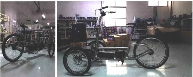
Figure 2-1: Current prototypes of the Persuasive Electric Vehicle
2.1.1
Design Considerations
As discussed in Section 1.1, since the vehicle operates primarily in a bike lane, the design specifications are determined based on European Union and American road de-sign guides. To this end, the Urban Bikeway Dede-sign Guide by National Association of City Transportation Officials (NACTO) [11] and Cycling Policy Guide Infrastructure
by Promoting Cycling for Everyone as a Daily Transport Mode (PRESTO) project [6].
The following design considerations are explained based on the primary criteria for operating legally and safely in a bike lane:
o Vehicle footprint - The typical specifications for bike lane width as well as bike length is 1.5 meters - 2 meters as shown in Figure 2-2. Thus, the maximum limits for the width and length of the vehicle footprint are chosen as 1 meter and 2 meters, respectively.
0,875m !E O)Sm0 E 0,625m 0,50M
Figure 2-2: Free space specification for bike lanes.
e Front wheel steering - On a front wheel steering vehicle, the self-righting effect created by the mechanical trail works with the self-aligning torque of the me-chanic trail. These two forces work together in balance to keep the wheel in its intended position. Front wheel steering systems also offer better control to the driver.
e Stiffened Tilting Suspension Mechanism - Lateral stability is an important as-pect of vehicle drivability and performance during turning maneuvers. Thus, most three-wheeled vehicles are designed with passive or active tilting mech-anisms [35] to compensate for the effect of lateral acceleration and remain in balance. The PEV suspension mechanism is designed to be configurable be-tween passive and active systems. For the purpose of simplicity, the tilting mechanism is highly stiffened to reduce vehicle roll which will be explained later.
* Rear Wheel Drive - Just like a typical bike, the PEV is a rear wheel drive vehicle which provides natural ride conditions for passengers in comparison to
a complicated front wheel drive system.
Figure 2-3 shows a CAD model of the latest prototype of the tricycle chassis with the footprint dimension. The figure also illustrates the front wheel steering system, the stiffened tilting suspension mechanism as well as the rear wheel drive. It can be seen that it meets the specifications for operating in bike lanes as well as the design considerations mentioned above. The design also offers the advantage of easy serviceability and maintenance since it uses commercially available bicycle parts and components while offering a bike-like ride experience to the users.
1.85 m 0.95 m
Figure 2-3: CAD model of the PEV chassis with footprint dimensions.
Figure 2-4 shows the fabricated and assembled prototype of the vehicle chassis manufactured at a production facility of Pacific Cycle, Inc. in Taiwan.
Figure 2-4: Current prototype of the PEV chassis
2.2
Actuators and Controllers
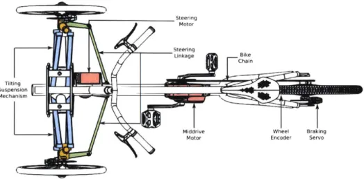
Figure 2-5 shows a schematic of the actuation system configuration for the PEV. The actuators and sensors required for controlling the vehicle motion are:
1. Steering Motor - The front wheel steering system is an Ackermann Steering Mechanism. The two front wheels are coupled to the steering motor through a dual four-bar linkage system which ensure proper kinematic and dynamic operation.
2. Mid-drive Motor - The rear wheel is connected to a mid-drive motor with a bike chain similar to a bicycle. As such, this provides only forward motion due to the presence of a hub ratchet in the rear wheel.
3. Braking Servo - The vehicle has a cable braking system operated from the handlebar which allows the passenger to brake it independently of the autonomy system. A braking servo is installed close to the rear wheel disc brake which
actuates the brakepad lever independent of the passenger braking cable.
4. Rear Wheel Encoder - Since the rear wheel is actuated by the mid-drive motor with a bike chain and hub ratchet, it rotates even when the motor is not running similar to a bike. The rear wheel angular velocity is required for estimating the
speed of the vehicle. A simple solution is to install a rotary encoder on the rear wheel.
It should be noted that all three motors need to be backdrivable to allow manual operation of the vehicle for a bike-like riding experience.
Steering Motor
Linkage Bike
Chain
Suspension E
Middrive Wheel Braking
Motor Encoder Servo
Figure 2-5: Schematic of the actuators required for the PEV.
2.2.1 Steering Motor Selection
The selected motor is a NIDEC 48R Brushless DC (BLDC) motor as shown in Fig-ure 2-6a. BLDC motors do not require commutators and brushes, have a long life, quieter operation, and high efficiency. A 144:1 planetary gearhead is attached to the motor for high-torque applications.
The rated power is 67W, with a nominal output torque of 0.2Nm (28.8Nm at gearhead output) and a current consumption of 3.8A. The motor also has hall sensors at the input side for position control which is important for controlling the steering angle of the vehicle.
The gearhead is connected to the actuated joint of the steering linkage with a timing belt coupler system with 2:1 gear ratio, effectively increasing the torque output to 55Nm which is sufficient for steering the vehicle with a human payload of 80kg. This also allows for backdriving the motor through the heavy gearhead which is required for manual operation of the vehicle.
2.2.2
Middrive Motor Selection
Mid-drive motors have two key advantages over hub motors:
9 Higher performance and torque when compared to a similarly powered
tradi-tional hub motor. One key reason why is that the mid-drive motor drives the crank, instead of the wheel itself, multiplying its power and allowing it to better take advantage of the bikes existing gears.
e Designed to make maintenance and service extremely easy. The motor assembly
can be removed and replaced by simply taking out two special bolts without affecting any other aspect of the bike. On the other hand, even basic main-tenance tasks such as taking off the wheel to change a flat tire become more complicated task with a hub motor in the rear wheel,
Since there is no legislation for electric bicycles in the US currently, the European Commission directives for two or three-wheel vehicles summarized in [29] are used for choosing the motor power. Article 1 (h) of Directive 2002/24/EC relating to the type-approval of two or three-wheel motor vehicles legislation stipulates that:
E-bikes and cycles with pedal assistance which are equipped with an auxiliary electric motor having a maximum continuous rated power of 0.25 kW, of which the output is progressively reduced and finally cut off as the vehicle reaches a speed of 25 km/h, or sooner. Pedal assisted cycles with a maximum continuous rated power of less than
0.25 kW and E-bikes that can be exclusively propelled by the motor do fall within
the scope of Directive 2002/24/EC.
Bafang MM G520.250 shown in Figure 2-6b is chosen since it meets the regulatory requirements for the PEV being classified as a cycle. The product has a BLDC motor with power rating of 250W operating at 36V with a 92RPM output speed and 95Nm output torque. The motor is powerful enough to operate in flat to moderately hilly areas which is sufficient for most urban environments.
2.2.3
Braking Servo Selection
Hitec HS-7955TG shown in Figure 2-6c is selected as the braking servo. The servo operates between 4.8V-6.OV with a stall torque of 1.75Nm and a no-load speed of 0.19 sec/60'. The servo also features titanium gearing which makes it robust and reliable for the critical task of braking.
2.2.4
Rear Wheel Encoder Selection
Accucoder TRi Tru-Trac shown in Figure 2-6d is chosen for measuring the rear wheel angular velocity. The encoder is integrated with a spring-loaded measuring wheel assembly in one unit. The spring-loaded torsion arm offers adjustable torsion load, allowing the encoder to be in contact with the rear wheel under typical road conditions. The encoder is mounted on the rear wheel as shown iP Figure 2-7b.
(a) Nidec 48R-vlT-002 (b) Bafang MM G520.250 (C) Hitec HS-7955TG (d) Accucoder TR1 Tru-Trac
Figure 2-6: Selected motors and encoders for front wheel steering and rear wheel drive
(a) Steering motor assembly (b) Rear wheel drive assembly
2.2.5
Motor Controller Selection and Configuration
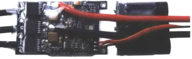
Two VESC BLDC Open-Source electronic speed controllers (ESC) shown in Figure
2-8 are used for controlling the steering and middrive motors as well as the braking
servo. VESC is an open source, highly modifiable ESC by Benjamin Vedder. The
VESC can be used with sensored and sensorless motors to achieve smooth start-up
from a stop versus traditional radio controlled ESCs which have trouble starting from a complete stop using Field-Oriented-Control (FOC) for BLDC motors. The VESC can also be connected to the computer with a mini-USB connection which allows for ease of communication.
Figure 2-8: VESC - An open-source electronic speed controller for brushless DC motors
The two VESC controllers used in the PEV are configured as follows:
" Steering Position Control - The Steering VESC is configured for sensored FOC operation for controlling the steering motor. The VESC receives position feed-back from the hall sensors on the motor side of the geared steering motor and uses an internal PID position control loop to ensure satisfactory performance. The VESC receives position commands from the compute system and sends the current position back to it as shown in Figure 2-9a.
" Rear Wheel Drive Velocity Control - Since the rear wheel is coupled to the middrive with a bike chain and ratchet mechanism, it is not possible to control the velocity and braking of the rear wheel directly with the middrive motor. Figure 2-9b shows the schematic for velocity control of the rear wheel. The
VESC receives velocity command from the host computer and applies a duty
external wheel encoder through friction drive and the ABI signal is received by the VESC to close the velocity control loop. The braking servo receives a PWM signal from the VESC to control the braking of the rear wheel. The rear wheel drive uses an internal switching control scheme for driving and braking the rear wheel.
PWM Signal Braking Braking Cable
Servo
Middrive voftge Middrive Chain Rear
VESC Motor Wheel
Position Fedback
Command Voltagne Seein
Position VESC Hall Senso Otor
Feedback Feedback A11 Signal
(a) Steering position control (b) Rear wheel drive velocity control
Figure 2-9: Drive system control schematics
2.3
Sensor Setup and Configuration
Among the many technologies which make autonomous vehicles possible is an array of sensors which help it to perceive its surrounding environment and localize with respect to it while operating safely.
Most sensors can be classified using two important functional axes: propriocep-tive/exteroceptive and passive/active.
" Proprioceptive sensors measure values internal to the system (robot); e.g.
vehicle speed using odometers, longitudnal and lateral accelerations using ac-celerometers, and angular velocities using gyroscopes.
" Exteroceptive sensors acquire information from the robots environment; e.g.
distance measurements using Light Detection And Ranging (LIDAR) sensors, location on earth using GPS, and vehicle heading with respect to earth's mag-netic field using magnetometers. Hence exteroceptive sensor measurements are interpreted by the robot in order to extract meaningful environmental features.
" Passive sensors measure ambient environmental energy entering the sensor.
Examples of passive sensors include temperature probes, microphones and CCD or CMOS cameras.
" Active sensors emit energy into the environment, then measure the environ-mental reaction. Because active sensors can manage more controlled interac-tions with the environment, they often achieve superior performance. However, an active sensor may suffer from interference between its signal and those be-yond its control. For example, signals emitted by other nearby robots, or similar sensors on the same robot may influence the resulting measurements. Examples of active sensors include wheel quadrature encoders, ultrasonic sensors and laser rangefinders.
Similar to most autonomous robots the PEV is installed with an array of sensors for localization, mapping and obstacle detection tasks. The four primary sensors used in the vehicle are:
1. Cameras - One of the biggest upsides behind cameras is the optical aspect,
which enables an autonomous vehicle to literally visualize its surroundings. Cameras are very efficient at object classification and scene segmentation using deep learning, are widely available, and more affordable than radar or LIDAR. Cameras were one of the first types of sensors to be used in driverless vehicles. Cameras make processing a computationally intensive and algorithmically com-plex task, but are able to process colors (making them better for interpreting surrounding scenery).
2. 2D/3D LIDARs - LIDAR is capable of scanning upto 100 meters in all di-rections, giving it the ability to generate an intricate 2D or 3D map of its surroundings. This map can be used to make informed decisions on reacting to different circumstances, and information can be instantly processed. LIDAR provides raw information using high-speed, high-power pulses of laser-light that are timed with the response of a detector to calculate the distance to an object from the reflected light to high degree of accuracy.
3. Global Positioning System (GPS) - The primary subsystem used for nav-igation and guidance is based on a GPS receiver, which computes present po-sition based on complex analysis of signals received from at least four of the constellation of over 60 low-orbit satellites. Recent GPS systems can provide location accuracy on the order of one meter which is a good start for the vehicle. However, the actual accuracy of the position information depends on factors like clock error, orbital error, relativistic effects, ionospheric and tropospheric delay, multipath error and instrumental biases, Also, a GPS receiver takes between
30 and 60 seconds to establish initial position, so the autonomous vehicle must
delay its departure until the first fix is computed.
4. Inertial Measurement Units (IMUs) - These sensors are rigidly fixed to
the vehicle. Each sensor has three gyroscopes, three accelerometers and three magnetometers, one pair oriented for each of the orthogonal X, Y, and Z axes. These sensors provide data on the rotational and linear motion of the vehicle as well as the yaw heading with respect to the earth's magnetic field, which then is used to calculate the motion and position of the vehicle regardless of speed or any sort of signal obstruction. Note that an IMU only measures the motion of the vehicle, so the initial location of the vehicle must be determined by a GPS or entered manually.
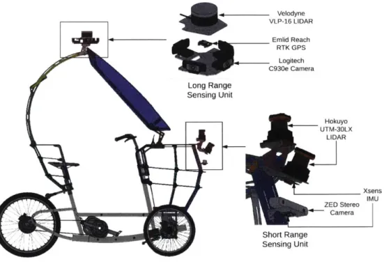
As shown in Figure 2-10 the sensors on the PEV are divided into two subsystems:
(1) Long Range Sensing Unit, and (2) Short Range Sensing Unit. The following
sections describe the sensors used in each subsystem and their configuration.
2.3.1
Long Range Sensing Unit
This subsystem consists of the following sensors shown in Figure 2-11:
1. Velodyne VLP-16 - The LIDAR provides a 3D pointcloud of distance mea-surements upto 100 meters using 16 laser/detector pairs with a 300 vertical field of view and 360' horizontal field of view. The lasers are mounted in a housing
Long Range Long Range Sensing Unit U Velodyne VLP-16 LIDAR Emlid Reach RTK GPS Logitech C930e Camera Hokuyo UTM-30LX LIDAR Xsens IMU ZED Stereo Camera Short Range Sensing Unit
Figure 2-10: Sensor setup on the vehicle.
that operate from 5 Hz to 20 Hz and acquire up with an accuracy of 3 cm which is sufficient for
to 300,000 points per second most urban environments.
2. Logitech C930e - An array of four off-the-shelf web cameras is used as vision sensors for perceiving the vehicle's surrounding environment. The cameras have a 3 Megapixel optical sensor with a 900 diagonal field of view and can capture upto 1080p resolution images at 30 frames per second.
3. Emlid Reach RTK GPS - Real Time Kinematic (RTK) is a technique used to improve the accuracy of a GPS system. Traditional GPS receivers on most robotic platforms only determine their position with 2-4 meters accuracy while RTK can give provide in centimeters using corrections received from a base sta-tion. Reach runs open-source RTK processing software called RTKLIB written
(a) Velodyne VLP-16 (b) Logitech C930e (c) Emlid Reach RTK GPS
Figure 2-11: Selected sensors for long range sensing unit
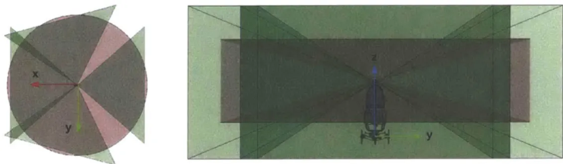
Figure 2-12 shows the horizontal and vertical FOV of the long range sensing unit. The red region shows the Velodyne VLP-16 FOV and green region the Logitech C930e webcan FOVs.
Figure 2-12: Horizontal and vertical FOV of the long range sensing unit.
2.3.2
Short Range Sensing Unit
The short range sensing subsystem consists of the following sensors as shown in Fig-ure 2-13:
e Hokuyo UTM-30LX - The LIDAR provides a 2D laser scan of distance mea-surements upto 30 meters using a single laser/detector pair with a 270' hor-izontal field of view at 40Hz update rate and 0.25' angular resolution. The PEV is installed with two Hokuyo LIDARs; one is horizontal with respect to the ground plane while the other is tilted at 300 from the horizontal to detect
* Stereolabs ZED Stereo Camera - The sensor is a passive stereovision device which constructs a 3D depth map using images from two cameras with a baseline of 120 mm. The camera provides a 3D depth map with a range of 0.5 meters
- 20 meters. The camera is configured to operate in 720p video mode at 60 frames per second.
* Xsens MTi 1-series IMU - As shown in Figure 2-10, two modules are in-stalled on the vehicle for sensor redundancy. With a roll/pitch accuracy of 1.00
RMS and yaw accuracy of 2' RMS under dynamic conditions, the output is excellent for state estimation and control of the vehicle.
(a) Hokuyo UTM-30LX (b) Stereolabs ZED (c) Xsens IMU
Figure 2-13: Selected sensors for short range sensing unit
Figure 2-14 shows the horizontal and vertical FOV of the short range sensing unit. The red region shows the FOV of two Hokuyo LIDARs and the green region shows the ZED Stereo camera FOV.
2.4
Compute System Selection
Over the last decade there has been an incredible decrease in the cost of computation time and in the size and power to process the data coming from the sensors. This point is critical in order to incorporate compact and affordable autonomy packages in current autonomous vehicles. Since the PEV is a slow-moving vehicle with an optimal number of sensors, there is no need for high-end computing units like NVIDIA Drive PX2 which is setting a standard in the autonomous vehicles industry.
While there are many options for onboard-computing power, the NVIDIA Jetson TX2 embedded computing unit poses a noticeable step-up in computational capabil-ities. The Jetson TX2 features the dual-core NVIDIA Denver2 + quad-core ARM Cortex-A57, 8GB 128-bit LPDDR4 and integrated 256-core Pascal GPU. Useful for deploying computer vision and deep learning, Jetson TX2 runs Linux and provides greater than ITFLOPS of FP16 compute performance in less than 7.5 watts of power. These features make it a suitable candidate for the PEV.
Figure 2-15: NVIDIA's Jetson TX2 embedded computing unit
In order to provide computational redundancy for a safety-critical application like operating in outdoor environment, the PEV uses two Jetson TX2s along with a host laptop computer to ensure that all the processes are running properly. The host
32GB RAM, and an NVIDIA Quadro M2000M graphics card.
A distributed computing architecture is proposed for processing the sensor data
and controlling the vehicle. In order to limit the computational load on each of the compute devices, one Jetson TX2 interfaces with the long range sensing unit while the other interfaces with the short range sensing unit. Both Jetson TX2s run obstacle detection algorithms and send only the necessary information to the host computer which runs the localization, planning, and control algorithms.
2.5
System Integration
This section provides an overview of the overall system architecture for power distri-bution and communication between the various components of the system.
2.5.1
Power Distribution System
Figure 2-16 shows a schematic for the power distribution on the PEV. The power dis-tribution is designed such that all the actuators, sensors, and computers are powered independently. The following is a brief description of the system:
" 36V 11.4Ah Li-ion Battery - This battery powers the middrive and steering
motors via their respective VESCs. The 36V output of the battery is stepped down to 24V for the steering drive VESC.
" 19V 23Ah Li-ion Batteries - Two of these batteries power each of the Jet-son TX2s. The JetJet-son TX2 connected to the long range perception sensors powers the four Logitech C930e cameras through a 4-port high speed USB3.0 PCIe adapter mounted on the development board. The Stereolabs ZED stereo cameras is powered through the USB3.0 port on the Jetson TX2 development board for short range sensing unit.
" 12V 1OAh SLA Battery - Two 12V 5Ah sealed lead acid (SLA) batteries connected in parallel are used to powerthe Velodyne and Hokuyo LIDARs while
a USB 3.0 hub with 12V input powers the Xsens IMUs and the Reach RTK
GPS with its 5V output.
36V 11.Ah Middrive
Li-ion Battery VESC
Steering 24V Voltage VESC Regulation Reach Seelb RTK GP S ZEDtera Powered SB 3.0 Hub Logitech C930e Cameras Xsens IMUs 4-f Pl USB 3.0 Card
19V 23Ah
FLong
RangeLi-ion Battery Jetson TX2 19V 23Ah ShortRange
Li-ion Battery Jetson TX2
Figure 2-16: Schematic of the power distribution for the PEV.
2.5.2
Communication Interface Architecture
Figure 2-17 shows the communication interface architecture for the various computing units and sensors installed on the vehicle. A brief description of the communication architecture is as follows:
" The host computer is connected to a powered USB3.0 hub which interfaces with
the steering and mid-drive VESCs, the Xsens IMUs, and the Reach RTK GPS. The host computer sends motion commands to the VESCs and receives the corresponding feedback from them while it receives the IMU measurements and global position information from the IMUs and RTK GPS devices.
" The short range Jetson TX2 is connected to the Hokuyo LIDARs using a USB2.0
hub connected to the USB2.0 port on the development board and receives the laser scan distance measurements. The Jetson TX2 is also connected to the Stereolabs ZED camera through the USB3.0 port available on the development board. Horizontal Hokuyo UTM-30LX Velodyne E 10Ah VLP-16 SLA Battery U Hokuyo UTM-30LX n
" The long range Jetson TX2 is connected to the four Logitech C930e cameras
using a high-speed 4-port PCe adapter mounted on the development board for high data throughput.
" All the computational units communicate with each other through a high-speed
ethernet switch. The Velodyne VLP-16 is also connected to the ethernet switch since it provides an ethernet interface. However, the 3D pointcloud generated from the Velodyne is only used by the host computer for mapping and local-ization tasks and the long range Jetson TX2 for the perception and obstacle detection tasks.
Xsens IMUs ReKaGh
Host cokputer USB 30 Hub teering
Long Range othe co n Short Range ftereolabs
Jetson TX2 EhreSwthJetson TX2 ZED Camera 4-port PCle
Velodyne
USB 2.0 Hub USB 3.0 Card VLP-16
' - -'-Horizontal Tilted
. -as IHokuyo UTM-30LX Hokuyo UTM-30LX Logitech
C930e Camera
Chapter 3
Software Implementation
As discussed in Section 1.1, full autonomy requires various tasks to be completed simultaneously: Sensor data is acquired, filtered, combined and augmented through estimators; perception algorithms analyze the sensor data to generate key informa-tion about the surroundings like detecting obstacles around the vehicle; moinforma-tion and behavior planning algorithms ensure that the vehicle moves towards its goal position safely; and low-level controllers ensure that the actuators operate desirably.
3.1
Robot Operating System
Since the onboard computing units are capable of running a full Linux system, the Robot Operating System (ROS) [27] was used as the base framework for the following reasons:
" Open-source, meta-operating system that provides services like hardware ab-straction, low-level device control, implementation of commonly-used function-ality, message-passing between processes, and package management.
" The ROS runtime "graph" is a peer-to-peer network of processes (which can also be distributed across machines) that are loosely coupled using the ROS communication infrastructure.
" Built-in and well-tested messaging system manages the details of
communica-tion between distributed nodes via the anonymous publish/subscribe mecha-nism.
" Because the publish/subscribe system is anonymous and asynchronous, the data
can be easily captured and replayed without any changes to code.
" A distributed parameter system provides an easy way for tasks to share con-figuration information through a global key-value store. This also allows easy modification of parameter settings without rebuilding the code.
" A powerful development toolset which supports introspecting, debugging,
plot-ting, and visualizing the state of the system being developed. The underlying publish/subscribe mechanism helps to introspect the data flowing through the system, making it easy to comprehend and debug issues as they occur.
" An extensive collection of graphical and command line utilities that simplify
development and debugging.
Before delving into the details of the software architecture, it is important to understand some common terminologies in the context of using ROS as follows:
" Nodes - Nodes are processes that perform computation. ROS is designed to be modular at a fine-grained scale; a robot control system usually comprises many nodes. For example, one node controls a laser range-finder, one node controls the wheel motors, one node performs localization, one node performs path planning, one Node provides a graphical view of the system, and so on.
" ROS Master - It provides name registration and lookup to the rest of the Computation Graph. Without the Master, nodes would not be able to find each other, exchange messages, or invoke services.
" Messages - Nodes communicate with each other by passing messages. A mes-sage is simply a data structure, comprising typed fields. Standard primitive
types (integer, floating point, boolean, etc.) are supported, as are arrays of primitive types.
e Topics - Messages are routed via a transport system with publish/subscribe semantics. A node sends out a message by publishing it to a given topic. The topic is a name that is used to identify the content of the message. A node that is interested in a certain kind of data will subscribe to the appropriate topic.
3.2
Software Architecture
This chapter discusses the software architecture implemented to enable the neces-sary autonomy features on the PEV. Figure 3-1 shows a schematic for the various nodes running on the host computer and the Jetson TX2s and messages passing between them. The oval containers denote the nodes and the arrows denote the publish/subscribe action of each node. The red nodes denote the various algorithms running on the system while the green nodes interface with the corresponding hard-ware. The following is a description of the functionality of this architecture:
" The host computer runs the ROS Master which provides the name registration and lookup to the rest of the software system.
" The Long Range and Short Range Jetson TX2s run only obstacle detection algorithms since it is a computationally intensive task as discussed below:
1. Long Range Obstacle Detection node receives 3D pointcloud from the
Velo-dyne VLP-16 node and camera images and the corresponding extrinsic and intrinsic parameters from all the four Logitech C930e nodes. The long range obstacle detection algorithm then finds all the obstacles in a 5 meter
- 20 meter radius of the vehicle since the long range sensors have almost
3600 field of view. The node runs at an update rate of 10Hz which is sufficient to process all the data.
It detects obstacles in 0.5 meter - 5 meter range within the FOV of the
short range sensors and runs at an update rate of 40Hz since the PEV has to react quicker for closer obstacles.
3. Both nodes pass the relative position information of each obstacle detected
to the Motion Planning node running on the host computer. This reduces significant computational and data handling complexity for the host com-puter.
The following is a brief description of each of the nodes running on the host computer:
1. State Estimation node receives the horizontal and tilted IMU
measure-ments corresponding to the current state of the vehicle from the corre-sponding nodes, the global position information from the Reach RTK GPS node, the vehicle speed information from the Middrive VESC node, and the steering angle information from the Steering VESC node. It then fuses all the information to provide an absolute position and velocity estimate of current state of the vehicle.
2. Mapping and Localization nodes receive the current state estimate from the state estimation node as well as the 3D pointcloud from the Velodyne VLP-16 node to build a map of the environment or localize with respect to one, respectively.
3. Motion Planner node receives the current state estimate from the Long Range Obstacle Detection and Short Range Obstacle Detection nodes
gen-erates a motion plan for achieving the task of moving from point A to point B. It also computes the corresponding motion commands for desired vehicle speed and steering angle which it sends to the Vehicle Control node. 4. Vehicle Control node receives the desired motion commands from the Mo-tion Planning node and computes the corresponding actuator commands for the Middrive VESC and Steering VESC. It also ensures that the
mid-drive VESC and steering VESC are working satisfactorily by receiving feedback from the corresponding nodes.
Long range Jetson TX2 Host Computer Short range J
/- --- --- -R M-s- - - - ---
---etson TX2
bstacle Deteti L ffciio Motion Planning State Estimation
I Mapping Vehicle Control -Welodyne VLP-16
orizontal Xsens IM Middrive VESC
Logitech C90e ( Ea RTKGP
Tilted Xsens IMU Steering VESC
Short Range bsacte Detectio a E: ZED Camera - -I I Horizontal Hokuyo
Figure 3-1: Schematic of the software architecture for autonomous operation.
Figure 3-2 shows the visualization of sensor data acquired through the various hardware interface nodes.
Figure 3-2: RVIZ visualization of data from the sensors installed on the vehicle.
Figure 3-3 shows an example of the ROS Node Graph for an implementation of the state estimation node which is run offline with collected data.
A core aspect of building autonomous vehicle software is data-acquisition for offline
development, data processing and testing for the software development effort and
itejmu
steeringjeum
Mddybdv. .. Vfng t. Meedachnt.rip.N/Yo-dbCkwksh fnusWr w -- lnuatrdu hr
r-dchftkyjs dOva fvIllodometiry_WmnjmbIlshe
Figure 3-3: ROS Node Graph for State Estimation node
promote flexibility and modularity in the system. One of the core features of ROS is the recording and playback of messages. Because the publish/subscribe system is anonymous and asynchronous, the data can be easily captured and replayed without any changes to code.
Table 3.1 gives the update rate and bandwidth of the most data-intensive sensors in the system. All the sensors used in the system occupy approximately 12.5MB per second of data collection.
Table 3.1: Update Rates and Bandwidth of Sensors
Sensor Type Topic Name Message Type Update Rate Bandwidth Velodyne /velodyne-points PointCloud2 10Hz 5.84MB/s
/camera-top-front CompressedImage 10Hz 918.84KB/s Logitech /camera-top-right CompressedImage 10Hz 964.85KB/s
C930e /camera-top-left CompressedImage 10Hz 925.42KB/s
/camera-top-rear CompressedImage 10Hz 956.32KB/s
ZED Camera /camera-zed CompressedImage 30Hz 1.27MB/s Hokuyo /horizontallhokuyo LaserScan 40Hz 356.75KB/s
Chapter 4
Sensor Fusion
For most urban environments, it is safe to assume a two-dimensional pose for the vehicle. Let the two-dimensional pose of the vehicle be defined as p = (x, y, 0)T
and the corresponding velocity as
y5,
where x and y are the position, and 0 is the orientation defined in the global coordinate frame defined as an ENU coordinate system as shown in Figure 4-1. Also, let the vehicle configuration space parameters be defined as q = (v, 0, q)T where, v is the vehicle's heading velocity,#
is thesteering angle, and is the steering angle.
Since the PEV has an Ackermann steering mechanism, a simple car model can be used to describe the [18] kinematic motion of the vehicle which is defined as:
V oCos#0
P = (q) -v sin $ (4.1)
_v -tan 0
where, L is the length of the vehicle.
A critical challenge for all mobile robots is the ability to localize itself in a given
environment [19]. This task can be achieved through the robots sensors, which provide both proprioceptive and exteroceptive data. However, sensors are imperfect, and their measurements are prone to errors. The objective with sensor fusion is to combine
V
Y '
X
Figure 4-1: Local geodetic coordinate frame XY in ENU coordinates; X is East and Y is North
measurements from different sensors to improve the quality of information such that the combined information becomes more valuable than the information would be from each individual sensor [20].
A frequently used sensor fusion algorithm is the Kalman filter, which is a
recur-sive filtering method for discrete data that was developed by Rudolph Kalman and published in 1960 [16]. The Kalman filter enables estimation of past, present and future states of linear systems by using measurements in a fashion that minimizes the least mean squared error (LMSE). Many systems are nonlinear and in those cases the Extended Kalman Filter (EKF), a filter where the system is linearized around a working point, can be used.
While other ROS packages exist that perform generalized 3D state estimation for unmanned aerial vehicles (UAVs), unmanned underwater vehicles (UUVs), and unmanned ground vehicles (UGVs) operating outdoors [22], they are often difficult to apply to simple systems like slow-moving car-like robots since they use a differential drive motion model internally.
The following sections cover the implementation of a Discrete Kalman Filter for fusing vehicle heading estimates from two IMUs and an Extended Kalman Filter for