S(O•rI'.G OF PARpTICLi>S by
ROGER LEE MHcCARTHY
B.A., University of Michigan 1972
B. S . (i, •- .), University of Michi an
1972
3UBMITTED IN PARTIAL FULPILLMEN'T OF iTL .QUIRE'SN-rS
FOR TH4E DEGREE, OF 0ASrEi OF SCCI '2NC2• AXD CH AiiICAL ,GIN:,3EE,
at the
:,ACS AC.HiUS.TS NTSTITUTh OF
TECHN7
CTOLOG
YJune, 1973
Sig•'nature of Author . ... .a -.-.. . . k * * * &
Deoa ment of Mechanical rnwineerinr
May 11, 1973
Certified by ...Thesis uervsor
A Thesis Suoervisor
V / v
-Accepted by ... ...
Chairman, Departmental Committee on Graduate Students
Archives
(JUL 10 1973
-2-DESIGN OF A ,ECTION VORT, X FR. DE-SIITY SO, 0P CTIN OF PARTICL.'ES
by
ROER LEE i!cCA.RTHY
Submitted to the Department of iechanical wnqineerin7 on May 11, 1973, in partial fulfillment of the
require-ments for the deg'ree of MIaster of Science and Mechanical
EnTqineer.
A.B3S i'RtA.C T
This thesis describes the attempts to make a vortex density classifier operational. Specifically an existing: prototype of a device which -Yenerated an air vortex had been built but would not function as desi-. sz- ned . T.he air vortex subjects injected uniform oarticles to a balance of fluid forces which should force the oarticles to travel in circular orbits, the radii bein,; a function only of their density. Comouter investigation revealed that the shaoe of
the classification section was such as to cause thick boundary layers and nonsymmetric airflow.
A. new classification surface, with acceptable
airflow, failed to correct any particle orbiting
oroblems. This oromoted the investigation of transient oarticle behavior in the airflow. This revealed that oarticles failed to orbit because of their interaction with a fluid boundary layer at the lower surface of
the classification section. Furthermore, even with no
boundary layer interaction the time required by an injected narticle to achieve an equilibrium orbit was of the order of 30 seconds, far too long-. However,
transient behavior was found to be a strong function
behavior is proposed. Iransient behavior is quick, hence a larI.ge throughput can be achieved and the dimensions of the classifier kept relatively small.
Thesis 'Suoervisor: David Gordon Wilson
-4-AC •I • WLEmDEM .,. T
I wish to acknowledge the aid, advice, and
most imnortantly, the ercouragement of Profesor
David Gordon Wilsorn, without whose help this
oroject would not have been completed. This project
and my work have been made possible through prant
number EC-00333-2 provided by Solid Waste Research
in the Office of Research and Monitoring, 1National
Environmental Research Center of the Environmental
TABLE O•') CCNTi,•
S
i t le Abstract Acknowled P'ements List of Fiqures ForwardChapter I: General Introduction
Cha
Cha
Section 1-1: Anproach to the refuse treatment problem
Section 1-2: Vortex Classification
Section 1-3: Forces ýroverninp particle
behavior in vortex classifying section
pter 2: Testino: and Modification of the Original Prototype
S•ection 2-1: Abstract
Section 2-2: Problems inherited with the protot y pe
Section 2-3: Testinq and efforts to correct problems
pter 3: Computer Analysis and Photof'raphic
Investigation of Criginal Prototype
Section 3-1: Abstract
Section 3-2: Kathematical model. of vortex flow
Section 3-3: Application of modeling procedure to actual prototype 12 12 16 21 26 26 2/0 2Q 43
43
4352
-6-PAGE
-)ection
3-4: Fhotorraphic investigation ofparticle behavior 60
Chapter 4: Investigation of Transient Particle
Behavior by Computer 69
Section 4-1: Abstract 69
Section 4-2: Yathematical description of
transient behavior 69
Section 4-3: Numerical prediction of transient behavior and awreement with
observed behavior 74
Section 4-4: Verification of numerical orediction o1
Chapter 5: Design Concept for Density
Classifi-cation on the Basis of Transient
Behaývior in a Vortex :Section .6
Section 5-1: Abstract P6
Section 5-2: Transient behavior characteristics
Section 5-3: Selection of the optimum
classification surface 91
Section 5-4: Design of "optimum" classifier 96
Section 5-5: Vortex and ballistic separators 100
Summary of Conclusions 104
Re c omme ndat i ons 107
Appendix I 10
Section Al-I: Drag coefficient versus Re 1for
various three-dimensional shapes 109
Section A1-2: Velocity of airflow versus total pressure in .,age oil height.
;Plot and computer listingp of data. 110
Section A1-3: Airflow data for prototype as
PAfE Section A.1-4: Section A1-5: Section A.1-6: Appendix II Section A.2-1: Section A.2-2: Section A2-3:
Airflow data for prototype after modifications
Airflow data for prototype with increased power
Airflow data for prototype with horizontal surface
Calculated flow parameters for classification surface with angles of three and six degrees
Calculated flow parameters for horizontal classification
surface
Calculation of optimum surface
DCR/DR = -1, Computer data and plot Bibli o,:raphy 117 122 127
130
131 177 1 1 161Q_
IS'T OF FICURES
FIGURE PAGE
1. Mass-flow assumptions for plant design 13
2. Cross-section view of vortex classifier 1)
3. Photograph of original prototype 19
4. Isometric view of classifying section with
flow comoonents 22
5.
Sheet metal cover with liu 296. Yaw meter and pitot tube 31
7. Diairam of the 12 flow measurement positions 32
R. Layout of the diffuser vanes or wedges 34
9. Profile of classification section 35
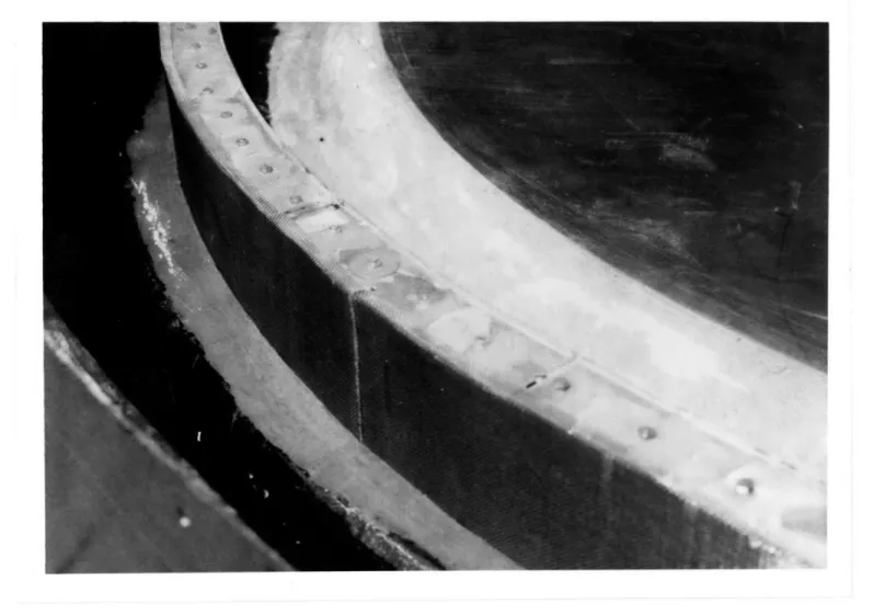
10. Photo.raph of annulus with zao 37
11. Photograph of annulus with gap filled and
screen installed 30
12. Cross-section of modified classifier 39
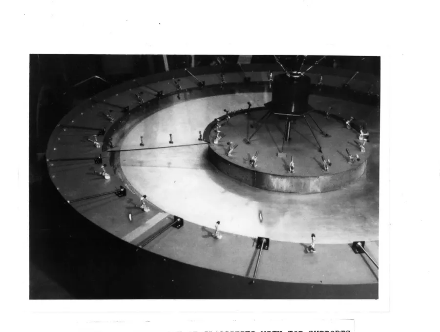
13. Photograph of classifier with top supports 41
14. Flow assumptions for flow model 46
15. Smoke test of classifier section 55
16. Prototype with classification section removed 57
17. Prototyre with radial ribs 59
1i . Prototype with horizontal surface installed 59
PAGE
20.. Photoranhic backroiud of prototyue 63
21. Calibrated oarticle injector 64
22. 3quare block interactin-:: with boundary layer 66
23. Sphere interacting with boundary layer 67
24. Plot for particle inJected at 135 inches/sec 76
25. Path for particle with 100 surface 79 26. Path for particle with 100 surface, 20seconds 90
2?. Phot;ora. h of particle oath 82
22, Predicted poath of 13 lbm/ft3 particle in
actual nrototype 23
29. Path of particle ir prototype with 100 surface,
=10 ilbm/ft 3 !
30. Path of particle in prototyoe with 100 surface,
= 20 Ibm/ft3
-9
31. Path of particle in prototype with 100 surface,
= 30 Ibm/ft3 90
32. Path of 13 Ibm/ft3 particle in prototype with
optimumr surface 93
33. Particle paths in optimum classifier 94
34. Top view of prototype with four classification
sections 99
-10-FOREWORD
Since the beginning of the present decade, a
nationwide consciousness of the state of the
"environ-ment" has appeared. This issue has crept into the
political area (and jargon) as evidenced by the concern
expressed by almost every candidate for public office.
This seems to portend a significant resource allocation
in the future to make man's conduct more compatible
with his environment.
Perhaps the largest single contaminator of the
natural state is man's discarded solid refuse. Present
disposal methods are usually one of two types, landfill (or seafill) or incineration. Landfill has the inherent
disadvantage of being quasistatic at best. Even when
done with some foresight as to environmental effects
(which is not often the case) the landfills will
eventually all be full and the resources in them denied
to future generations. Burning of refuse usually has the
effect of changing pollution from that of land or
water to air. The tougher nationwide air pollution
and land use laws are quickly rendering both these
The ideal solution to this problem would obviously
be to reuse all discarded material in the production of
new products. However, such a solution is not practical
given the present state of the waste-reuse art. The
problem is formidable. Everything now used by man (with
the possible exception of large structures) shows up in
discarded refuse. The difficulty of sorting refuse is
compounded by the fact that most municipalities use a
single pickup method of collecting refuse, for economic
reasons, thus insuring that refuse, when it arrives at
the disposal facility, is a thoroughly mixed collection
of rags, dirt, metals, plastics, glass, garbage, wood,
-12-CHAPTER I
GENERAL INTRODUCTI ON
Section 1-1: Approach to the refuse-treatment problem
The project of which this thesis work has been
part is investigating ways to solve the reclamation
problem. Primarily we are concerned with municipal
refuse. We are attempting to develop a prototype of a
facility that could be used by medium and large-size
municipalities to recycle their refuse. Since past
attempts at getting consumers to separate refuse by
material have proved largely ineffective, our system
proposes to deal with the refuse as it comes from the
single collection truck. We propose to divide the
multi-component stream in the manner shown in Fig. 1.
Research currently being carried on by other members
of the project will refine the percentages of refuse
that actually fall into each category, but these figures
represent our design assumptions.
The paper and plastic film will be removed by a
suction fan as the refuse passes over a vibrating screen.
The vibrating screen will also sort the incoming material
Plastic 1% 4on% n 30/ having reclaim value
Fig. 1: MASS-FLOW ASSUMPTIONS FOR PLANT DESIGN
-14-2" from the larger objects. Ferrous material will be
removed at the vibrating screen by magnetic means. The
small items are ground up. The large items are placed
separately into carts where their infrared and
accelero-meter signatures are examined (infrared signature may
also be used to separate paper from plastic film).
Materials will then be dumped into appropriate bins
depending on whether they were glass, aluminum, plastic,
wood, etc. Some inhomogeneous objects, such as a
transistor radio, would be unclassifiable and hence would
be dumped for grinding. My thesis device is concerned
with the inhomogeneous and the small non-magnetic items, which we expect to compose roughly 50% of the incoming
refuse by weight.
The device I have been working on would sort the
small, non-magnetic items (some of which will be derived
from the large items that were inhomogeneous and were
subsequently comminuted)by density. It would require
that members of both classes of items not of the
appropriate size be ground first. Grinding should reduce
the objects to pieces a higher proportion of which are
homogeneous. This should result in purer reclaimed material.
It is a legitimate question at this point to ask
enough to be recycled. Soft rubber, asphalt, coke,
paper, ebony and boxwood, to mention a few, all have
species with the common density of 69 pounds per cubic
foot (ref. 3 ). But fortunately, waste reclamation has
an economics of its own which gives an affirmative
answer, as follows, to this question.
Certainly 100% accurate sorting would be the most
desirable. But solid refuse carries a disposal cost.
After collection it can cost from $2.00/ton to $20.00/ton
just to bury or burn it. Thus we really need only to
get the refuse in a form that is usable even if it had
no commercial value. Ideally the sorted refuse would
be in a purity that has commercial value so that the
cost of recycling would be borne totally by the sale of
the recycled material. But a municipality would be
ahead to pay an amount per ton equal to the alternative
costs of disposal to sort material into a form with
enough purity that processors of raw materials would be
willing to use if it cost them little or nothing. As
the technology of raw-material processing improves it
can serve only to help the economic feasibility of our
system. Thus it is hoped that materials of a common
density will be in ratios such that one material
pre-dominates. Certainly paper and wood would form the
-16-(
as raw material for paper. However, the real resolution
of this issue will come with the final testing of the
plant with real trash.
Section 1-2: Vortex classification
It was originally planned to do density sorting in
an annular air vortex chamber, which creates an air
whirlpool in which particles get stratified in stable
orbits, the radius of the orbit hopefully being a function
only of the material's density. A machine employing
this concept was constructed for the project last year
by Michael H. Corbin (ref. 1). Before the decision was
made to build a vortex classifier, several other types
of air-classifying schemes were investigated.
Specifially, Ora Smith and Professor David G.
Wilson investigated the Stanford Research Institute
Zig-Zag Air Classifier and some ballistic separators
(ref.9 ). Initial vortex experiments were conducted by
Felix Mascolo (ref.8 ) who employed a radial outward
diffuser. The results were encouraging; however, his
attempt to build a barrel-shaped classifier employing
the principle proved unsuccessful. Michael Corbin took
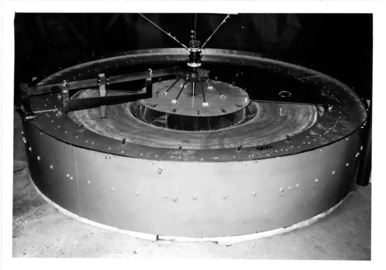
employed an inward-flowing air vortex. A cross-section
view of this device can be seen in fig. 2, and a
photograph of the actual device is in fig.3.
The operation of this device is fairly simple.
Part 5 is a fan which drives the air in the circular
path indicated by arrows B, B', and D. Part 18 is one of
six radial diffusing vanes which hold up the inner annulus
or "doughnut". The air goes between these vanes in its
outward path, turning the corner at the outside as
indicated by arrow B. The air then travels up and through
the turning vanes shown in part 4: these impart a
tangential component to the radial airflow. The air
then travels over the separation surface, part 9, and
under the cover of the separation annulus, part Y. This
surface was designed so that particles would orbit stably
in orbits that would be greater in radius than point 7, but less than point 6. Part 20 is a screen to filter out
erratic particles and to prevent them from reaching the
fan. The air then returns to the fan shown by arrow D.
The purpose of this recirculating flow was to conserve
the kinetic energy imparted to the flow so that in the
steady state the fan would have to add only enough energy
to compensate for that dissipated by friction. This
r FIGT•Rl 2 : CROSS SECTON VIEW
Part; 4 - hTurninpg vanes Part 18
Part 5 - Fan Part 20
Part 6 - 3Beinning ioint of Part 22
classification surface Part 23
Part 7 - ;'noint n of Part 25
classification surface Part Y Part 17- Dri-ve Shaft
OF VORTEX CLASSIFIER
- Diffuser vanes or "wedges"
- Screen
- Inner annulus or "doughnut"
- Fiberglas corner fillet
- ch chiot
-20-drove the fan through a four-speed automotive transmission.
The device was built as shown and preliminary
testing done with orbiting spheres. The results were
encouraging but inconclusive, the particle behavior being
somewhat erratic. Work was then carried on by Robert R.
Rodgers (ref.
5
) who made some modifications. Referringagain to fig. 2 , the following changes were made. The
separation surface, which originally had been fabricated
from styrofoam and "plasticene" to facilitate forming,
was replaced by an aluminum-sheet surface, which proved
much smoother and more uniform. The original 5-hp
motor was replaced by a 10-hp motor, in the hopes of
achieving greater airflow rates. And finally part Y,
which Michael Corbin had originally constructed out of
aluminum with a viewing window, was replaced with a top
made completely out of Plexiglas, so that particle
behavior could be observed at all points of orbit.
This was essentially the state of the device when I
Section 1-3: Forces governing particle behavior in
vortex classifying section
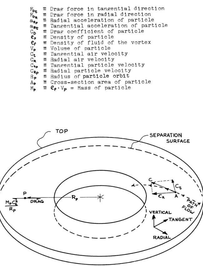
It is desirable at this point to get a thorough
understanding of how the vortex classifier works. A
two-dimensional isometric view of the classifying
sec-tion can be seen in fig. 4, along with the notation
deno-ting relevant parameters. The airflow is depicted by
the labeled arrows. The turning vanes give a tangential
component to air traveling in the inward radial direction.
Thus if we look at the instantaneous velocity vector
of an air particle A traveling on path H we see its
velocity, C, can be resolved into two components; a
tangential velocity C0 , and a radial component CR. Now
if the flow is truly one dimensional at any point with
the same radius as A, by definition the flow should have
the same tangential and radial components at any height
in the chamber. Hence the only variation in the flow
parameters should be in the radial direction. If we now
turn our attention to particle P we can examine how
this air flow affects the particle. Assume particle P
is not in contact with either top or bottom boundary
layer. For the particle to be stable in equilibrium
what forces have to be balanced ? In the tangential
Draw force in tangential direction Drag force in radial direction Radial acceleration of particle Tangential acceleration of particle Drag coefficient of particle
Density of particle
Density of fluid of the vortex Volume of particle
Tangential air velocity Radial air velocity
Tangential particle velocity Radial particle velocity Radius of particle orbit
Cross-section area of particle
ep.Vp = Mass of particle
FIG. 4: ISOMETRIC VIEW OF CLASSIFYING SECTIOUN WITH
FLOW COMPONENTS FDt
FN
aRp aitt CDep
e V, Ct Cao CSp RRp Ap MP "T"/" n"velocity C. If it were slower or faster a drag of
force of magnitude:
F = -*C*A.p ** (C, - C )
would act to speed up or slow down the particle until
it reached velocity Ct , at which time this force would
disappear. (CD is the drag coefficient and is defined
by this equation; it has been found to be a function
principally of particle shape and, to a lesser degree, of the Reynolds number of the relative flow
Re = (Ct - C p).l.e
where 1 is a dimension and }p is the fluid viscosity).
In the radial direction the force balance is more
complicated. For the particle to be in equilibrium in
a circular orbit with orbital velocity Ct it is necessary
for the air flowing inward to impart an acceleration to
the particle of the magnitude:
a
=
a RpRp
To accelerate a mass requires a force which must come
FD =a·C_ D*pA - (C )Z
Since in the steady state the particle stays at a constant
radius it has no radial velocity, only an acceleration.
Thus, for a stable orbit, the acceleration force required
for a circular orbit and the drag force provided by the
air flow balance, or:
Mp = D (CR) But:
a R
P =
Mp
= . VP
aRp - p Therefore:R
2.Vp*
ep*C.
P- CD , A.p•. e CRand since the value of Co, Ct , C, and (Vp /Ap ) are
all fixed for a standard particle, in a vortex of fixed
speed and geometry, the equilibrium radius would then
only be a function of particle density.
The conceot of separation then is to inject
pa.rticles into the air stream of the classifier. They
acting on them. The particles could then be removed, and
the particles at a common radius should have a common
density.
This analysis was made assuming a few important
simplifications. First, the interaction with the top
and bottom boundary layers could be ignored. During the
original design of this device, it was assumed the
parti-cles would never interact with the top of the classifier,
and would never contact the bottom due to the Magnus
effect (rotational lift) that will come from the lower
side of the particle coming in contact with the slower
boundary-layer air, giving the particles "spin" (ref. 4). Also, the possibility of particle interaction was
ignored. I did not see how to consider this problem
analytically, therefore it had to be studied experimentally.
Finally, CC is assumed constant over the range of fluid
velocities of the classifier. This assumption requires
some care be used in actual construction of a classifier,
since this is not true in all velocity regions. In
Appendix I, Section Al-I there is a plot of Cp vs
Reynolds number for some simple shapes.
In summary we see the vortex classifier is designed
to separate particles that are similar in shape but of
differing densities by creating a fluid-force balance
-26-CHAPTER 2
TESTING AND MODIFICATION OF THE ORIGINAL
PROTOTYPE
Section 2-1: Abstract
The first six months of this project were spent
trying to modify the existinw prototype to the point
where it functioned as designed. The changes were aimed
at improving particle behavior. The particles failed
to travel at the tangential velocity of the airflow, and
had very erratic orbits. Unfortunately all improvement
efforts, which were directed primarily at the air flow
patterns, and which are chronicled in the following
sections, proved unsuccessful.
Section 2-2: Problems inherited with the prototype
I began work on this project in September, 1972.
Initially the prototype vortex classifier was operable
only intermittently due to problems with the automotive
drive train, but these problems were quickly solved and
At the conclusion of Michael Corbin's work the
testinv of this device had been confined to balls that
rolled continuously in contact with the bottom surface.
Although the desiqn analysis presumed that particles
would be airborne when solving the fluid-force balance
expressions, denser balls generally took larger orbits
as theory would predict. However, the original
"plas-ticene" (or modeling clay) surface was fairly irregular
and Robert Rodgers placed a sheet-aluminum surface over
the plasticene so the balls would have a more uniform
surface to roll on . Even a uniform surface failed to
make the rolling spheres take stable orbits, where the
orbiting velocity was in equilibrium with the tangential
velocity of the air flow.
Inevitably, the surface and spheres had small
imperfections that were blamed for their poor
perfor-mance. It had also been found that to make the spheres
orbit even erratically it was necessary to inject them
with a tangential velocity component at the point of
inter-jection.
I decided to work initially with materials that
were less dense than the rubber the spheres were cast
from (E= 60 lbm/ft3 ) in the hopes that airborne particles would avoid performance problems due to
-28-separation-surface fabrication. It was necessary to go
to lihter materials because the actual airflow of the
device was less than 1/3 the original design
specifi-cation. Some initial testing: of this type was done by
Robert Rod•rers with some encoura7innw results. Testin'
done with materials with a density of 20-40 lbm/ft
and with a variety of shapes ranping' from spheres to
cubes failed to yield any positive results. Some spheres
would roll in elliptical orbits for as long a desired
but would never assume a constant radius. Particles
that were li'ht enoug7h to become airborne inevitably
tended to fly very unstably until their orbit "decayed"
and they flew inward to be pinned against the filter
screen (part 20, fi'. 2). Because of the poor airborne
particle behavior it was concluded that the particles
must be subject to a radially asymmetric air flow.
Section 2-3: Testinp and efforts to correct oroblems
In order to test the symmetry of the flow, T modified Michael Corbin's ori'inal sheet-metal cover
with an aluminum "lip" around the outside and inside
edges, as shown in fi'. 5, so that the measurino nart, a 15"-diameter hole cut in the cover, could be rotated
-30-constructed the direction- and speed-measuring apparatus
shown in fig. 6, which consisted of a pitot tube and
yaw meter on a cobra head. By also taking a
static-pressure reading- at the same radius as the pitot head,
I was able to determine the speed of the flow, and the
yaw meter, connected to the "U" tube shown in the
photograph, allowed me to read the angle of the flow
from the protractor. The curve of velocity vs. pitot
gage fluid height can be found in Appendix I, Section A.1 -2.
Michael Corbin had performed a series of speed
and angle measurements at one angular position at
different radii and heights within the classifying
section. These showed the flow to be highly variant in
the vertical direction, contrary to design assumption
(ref. 1, p.55-57). The flow angles measured in various
radial positions also showed very poor correlation with analytical prediction. However, since a new surface
had been added, and hence the geometry changed, new
tests were in order. I took readings at 12 angular
positions as shown in fig. 7. The results are tabulated
in Appendix I, Section A.1-3.
One can see wide variations between angle and velocity dependinp on the angular position or height in
This device sits inside the 15" diameter hole in metal cover.
-32-rop view of classification section
B
\ 7I
DRIVE TRAIN1s
04'-4
1
%
I
3 Scale: 1"=14"7DIAGRAM Ok THE 12 FLOW .A;..URE.IN. PO SITIOiS
9
I0A
/I
II-i
FIGURE 7:heights or at a constant height would see constantly
varying flow conditions, and hence would never attain
a stable orbit.
Upon examination, it was noticed that the flow
at a point seemed to be identical with the flow profile
found 1800 opposite. There were eight large diffuser
vanes (part 19, fig. 2) holding up the inner annulus
(part 22, fig. 2). A. top view of the placement of these
vanes can be seen in fig. 8. Because of the large
width of the rear of these "vanes" (which are shaped
more like wedges) it was thought the asymmetry they
introduce into the flow in the bottom of the classifier
was carrying through into the classifying section. The
large notch (point 25, fig. 2) was also thought guilty
of generating an unusually large boundary layer.
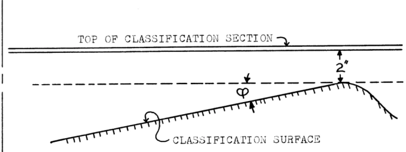
During original calculation of the classifying-section
surface shape it was thought the "wedge" profile
(as seen in fig. 9) would guarantee accelerating flow
which should suppress boundary-layer growth while wivinw
maximum particle stability, so the persistence of a
thick boundary layer in the classifier section was a
mystery at this point, but its existence was attested to
by its velocity measurements.
To solve this flow asymmetry and
FIGUFRE 8: LAYOUT OF THE DIFFUSER VAES] OR "1EDGES"
34TOP OF CLASSIFICATION SECTION
-A
CLASSIFICATION SURFACE
CP = CLASSIFICATION SURFACE ANGLE
-36-classifier from its state in fir.1O to that of fiw.11
Screen with an open area of only 50% was added to create
resistance in the flow that would suppress the apparent
"shadow" of the diffuser vanes that was oersisting. Part
23 (fig. 2 ) was also removed to further agitate the flow,
and the gap at 25 was filled with plaster and plasticene
and made smooth. Part 20, originally mesh with -" holes,
was replaced with resistance screen with 43% open area
to insure that particles would not leave the classifying
section and block the back of the newly added resistance
screen in front of the turning vanes. The classifier now
appeared as in fig.12.
resting began and particle behavior was observed.
Unfortunately, the airspeed was reduced considerably by
the newly added resistance screen. The device was
oriwinally designed to operate with an air flow of
730 ft/sec which required a fan speed of 600 rom (ref. 1
p.15). Unfortunately, without the screen the best
flow that wAs -btainable was 176 ft/sec, due to the fan
operatin. in an aerodynamically stalled condition. The
additional screen reduced this flow to 127 ft/sec. At
this speed only -" cubes or smaller would become airborne
and only if they were of a light material. Spheres of
2 oZ
-40-Testinw with such blocks proved futile, as they behaved
unstably and always decayed, when started in orbit, and
landed a•ainst the inside filter screen.
Another angular air profile was taken and the
results are in Appendix I, Section A1-4. Things seem
to have improved but are hardly cured. The an~ular
divergence and velocity differences are less, but still
bad enough to cause a particle to be very unstable.
Because of the resistance screen the diffusinp vanes were
discounted as the cause of asymmetry. Since the vertical
chamber heights at points 6 and 7 (fig. 12) were not constant at all points around the circumference of the
classifier, it was thought this variation might cause
asymmetric flows. To solve this problem top supports
were added as shown in fig.13 . These were adjusted until the separation chamber was of constant dimension
in all anaular positions. At the same time investigations
were made on how to increase the power to the classifier to increase the airspeed.
Investiqation of our electric power system to the
motor revealed that the motor was drastically underfused,
and underwired. The starter and fuse box had once been
used to power a 2--ho motor, and the wire and "heaters" in the starter had not been changed to accomodate the
-42-was rewired and fan soeeds of 800 rpm were obtained.
With both these chanqes another
angular-air-velocity profile was taken; the data points again are
in Apoendix I, Section A1-5. The velocities have
recovered due to the increased motor hl: however, the
fan apparently remained highly "stalled". With power
input from the motor at 10 hp, the airflow represented
less than 1 hp in its kinetic energy and pressure
com-ponents. A thick boundary layer was found to be present,
because of the reduced velocity and flow angle readings
taken !" off the classification surface (points 6 and
12 being a notable exception to this observation).
Particle behavior did not improve, other than larger
particles would again become airborne.
It was clear at this point that problems in the
performance of this device could no longer be attributed
to fabrication errors. Obviously some aspect of the
theory was misunderstood and our design was in error
accordingly. Hence it was decided to construct a
mathematical model of the device and investigate the
CHAPTER III
COMPUTER ANALYSIS AND PHOTOGRAPHIC INVESTIGATION
OF ORIGINAL PROTOTYPE
Section 3-1: Abstract
This chapter describes the derivation of a
mathematical model of the vortex flow, assuming
incompressibility and conservation of angular momentum.
The results revealed the cause of our boundary layer
to be decelerating flow. The classification surface
was changed to get continually accelerating flow, but
particles still failed to orbit. Photographic
inves-tization revealed the boundary layer or surface slowed
the oarticles when contacted and destroyed their
orbits.
Section 3-2: Mathematical model of vortex flow
Because of the poor results obtained with the
modifications described in the last section, study
was continued on the prototype by digital computer.
anwle inside the classification chamber at every position
was developed. Construction of the model required
assuming the flow incompressible and frictionless. Then
the flow parameters are determinant from conservation of
mass and anQgular momentum.
It was assumed first, as in the original design,
that the flow was symmetric in the anvular direction,
uniform in the vertical direction, and hence varied
with respect to only one parameter: the radius. The
actual flow deviated substantially from this model but
it was assumed for simplicity of programming. Secondly,
the flow was assumed substantially incompressible.
Since the highest static pressure difference in the
device was less than 0.1 inch water column, this seemed
valid. Finally, it was assumed that viscous shear in
the boundary layer did not bring about damoinjr of the angular momentum imparted to the flow by the turning vanes, i.e. the flow was frictionless. With these
assumotions a model_ can be constructed in the followinw
manner.
From actual speed measurements an actual volume
flow rate can be determined or one assumed. The radial
flow rate is then determinant, since the volume through
classification chamber must be equal (see fig. 14). The
tanwential flow velocity can be determined if angular
momentum is conserved, the flow being assumed to have
the angle of the turnina vanes when leaving the turning
vanes*, and the angular momentum beinz constant thereafter.
(See fig. 14). Thus the two components can be added and
the total velocity realized. Additionally, the angle of
flow for every point can be computed from the relation
Flow angle = 1800 - Arctan Tangential Velocity
Radial Velocity
Once the flow velocity and angle are known two
very important parameters for the operation of this
device can be determined. These parameters are, first,
the inward radial acceleration and, secondly, the
stability of a particle in an equilibrium orbit (the
tangential soeed of the air flow being equal to the
orbit velocity).
An acceleration in the radially inward flow is
very desirable for it prevents the flow from separating
from the surface. fig. 12 shows how the classification
surface slants downhill in the direction of the flow.
* while not strictly aerodynamically true, this proves
to be a fair approximation by the reasoninF illustrated in fiw. 14.
-46-)
VIEWS OF PROT
Ct
VOLUMi FLOW THROUGH
-JSURFA.CE A,B, & C, A.RE EQUAL,
CONSrMAT A3lGULA.R
MOMENTU9M MEALS :
IS DEFINED AS VANE AN.iLE. fiHE FLOW I<S ASS'U"~13'ED TO TAKE PHIS ANGLE. THIZS IS A VALID APPCROXIMATI ON BEC AUSE EVE N THOUGH ANGLE & IS GREATER, CIRCULATION WILL CAUSE 2HE FLOW TO ASSUME ROUGHLY ANGLE P.
nEASURhED DATA. VERIFY £THIS ASSUPTiF:I'I( .
FIGURE 14: FTL' ASSUMPTIONS FOR "LOW C` , •MODEL
n O
If the flow is decelerating, the result is similar to
that on. the reverse side of an airplane wing. The flow
experiences a negative pressure gradient, and hence any
perturbation of the flow grows and the boundary layer
becomes turbulent and separates. Hence the velocity
profile would cease to be independent of height, and
the flow would be two dimensional.
The importance of a stable equilibriun is fairly
obvious. If a particle is in an equilibrium orbit
(by equilibrium I mean in equilibrium with the fluid
forces discussed in Chaoter I), what is the effect of
a small perturbation? If the equilibrium is unstable,
the particle leaves the orbit never to return. If
the equilibrium is stable, the net result of the fluid
forces is to restore the particle to its oriqinal
position. This characteristic can be expressed more
quantitatively (see ref. 6).
The inward draq force from the air flow on a
particle was seen in Chapter I to be:
FDR = C A.p ~ (CR )2
This force must impart an inward acceleration, a ,
to the particle. An acceleration requires a force
Mp M c
M aRp P -RP
The particle is in equilibrium when these quantities
are equal. For this equilibrium to be stable, it must
be the case that
d(Net Force) (net Force = FR - Mp* aR )
d (radius)
is always a positive quantity. By using the sign
conventions established for force and radius established
by fig. 4, we interpret this requirement in the following
manner. If the particle is perturbed inward, dR is
negative, hence d(Net Force) must be negative or
M, a:p
>
FD , which means the outward force is greater than the inward drag. Thus the particle would moveoutward and compensate for the perturbance. The
opposite happens when it is p•rtnurbe:1 )utward
-ath matically, the complete expression is:
d(Net Force) d(Fo- Mp-aRg )
d(radius) dR
CD
dR
(
dR
\R
-"• ... .. . ... d Mp g+
in terms of r comes from the expression: Q = 2xrC,-h = constant where r - radius R h E chamber height or -
Qrh
21rh Thus (CR) = h and consequently,d(C,)
dr Q7 d-4-R
dR
Anwular momentum being constant gives us an expression
for Ct in terms of r. If the anzular momentum is always constant then:
H = CR(AT VANES) " sin (angle of turning vanes)-(radius) = constant
Therefore at all ooints in the flow
H
Ct
=
R
Ct
*
= H
-50-where H is the an-,ular momentum. With this expression
d Ct d H _
-dR R, dFR iR)
Substituting all this derivation into our original
expression yields:
d(Net Force) Co DA p ef+ d (1
-d(radius) 4-7tZ d-R Rd2H - R+
For a given classifier geometry, particle mass and size,
and flow rate, the stability as a function of radius
can be computed. The function
h=f (H.)
must be known for the solution of the stability function,
but an approximation of a surface, or discrete point
by measurements of actual classification chamber
heights can be inserted to get a solution.
The last parameters of immediate interest that
can be calculated from a mathematical model of the
classifier is the equilibrium particle density of a
given orbit radius, i.e. what would be the density of
a particle in a given orbit in equilibrium? Referring
to Chapter I, we derived the following expression for
S2 VP ep Ct P
C A.P*~ CR
This expression can be rearranged into the form:
p Co * Ap" e-Sp C *
RP
2
*V
C
Since the model predicts CR and Ct for each point
in the flow, the model will also yield an equilibrium
density for a particle of given volume, area, and
drag coefficient, once a value for the radius is
inserted.
In summary, from simple considerations of
conservation of angular momentum and incompressibility
we are able to construct a mrode' of the classifier
which will yield the flow velocity and angle at
every point. With this information we can compute
the radial acceleration, particle orbit stability,
-52-Section 3-3: Apnlication of modeling procedure to
actual prototype
Employing the procedure outlined in the previous
section I wrote a digital computer program that solved
the equations involved. Parameters such as flow and
surface shape had to be inserted, as well as
turning-vane angle. The program was therefore constructed
to solve for a variety of vane angles and surface
shapes, so that some insight could be gained into how
these parameters affected particle performance. The
results demonstrated the flow over the existing
classification surface was decelerating and therefore
separating.
For parameters that were relatively fixed on
my prototype such as volume flow, the measured value
of 126 ft3/sec was used. Two nested DO loops then
computed stability, CR, Ct, CTOTAL, DCR/DR and
density of orbit for a surface that was tilted 30 less
than the classification surface of the prototype
(relative to horizontal; see fig. 9 for angle
con-vention), roughly 60.
For each of these surfaces, all the quantities
were solved for vane angles varying from 10 to 350
as plots of the data obtained can be seen in Appendix
IISection A2-1.
Inspection of the plots yields some immediate
insight into the problem encountered with the prototype.
First DCR /DR is positive on the outside half of the
classification surface. This means that the flow is
decelerating and hence separating from the surface.
This accounts for the consistently lower velocity
values the flow near the surface appeared to have.
By looking at the radial velocity flow plot of a
classification surface with an angle of 60 we can see
that the deceleration is due to the height of the
chamber increasing too fast for the decreasing radius
to make the flow constantly accelerate. One can also
see that particles of the given density are stable.
An examination of the radial velocity plot of a 30 surface
shows that deceleration is still present at this
lower angle, and more importantly, stability decreases
as flow deceleration decreases. This makes good
physical sense; if the radial flow were faster at larger
radii a particle perturbed outward would meet more
restorinw force. But such a condition would require
the flow to decelerate over the entire surface, which
-54-separation; thus there is an immediate trade off.
To confirm the existence of deceleration and
separation a titanium-tetrachloride smoke-producing
solution was injected into the classifier (fig. 15)
Although it does rot show in the photorraph, a -epara.Lion
bubble was observed in the flow very close to where
the oro ram oredicted flow deceleration.
With this evidence a new surface was concluded to
be necessary. By reducin], the surface angle to 0
the flow would continually accelerate. Hence it was
decided to design a horizontal classification surface.
The computer calculation of narameters can be found
in Appendix II, Section A.2-2, One can see that the
stabi-lity is reduced, as exTected, but the radially inward
flow is continually acceleratin.r
The astute reader might well wonder why a para-bolic surface, that would just impart a very small
acceleration to the flow, and hence would Yive maximum stability, was not considered. It was, and the
com-puted shape of such an optimum surface will be discussed
later. But the fabrication of curved surfaces is ore
difficult than that of stral.ht surfaces and time
restrictions made flat surfaces the only practical
-56-plot it can be seen the densities that would be stable
in the present classifier. It was thus decided to
construct a horizontal surface 3.5" from the
classification-chamber top.
The old surface was removed, fig. 16 shows the
classifier with no classification surface. Wood ribs
were laid radially as shown in fig. 17, and a new
surface laid as shown in fig. 18. Much care was
taken to make the classification chamber exactly 3.5" in
height. This included cutting and planing each radial
support to height independently. The joints on the
surface were carefully made level, in order to avoid
the two sin'ular points, (points 6 and 12, fig. 7)
where the flow seemed to be "turned over", i.e. the
bottom layer having a wreater flow angle than the top.
It was felt this might be due to a discontinuity at
the joints of the aluminum surface.
A velocity profile was taken of the new surface;
data can be found in Appendix I, Section A1-6. rhings
once again are not perfect, the velocity beiny almost
uniform from top to bottom, but flow angle is still
not uniform.
Particle testing proved to be a complete failure.
FIGURE 17: PROTOTYPE WITH RADIAL RIBS
-"--1
I LI OI I
-60-equivalent to 126 cubic feet per second) to cause all
but the very lightest materials to become airborne,
and even airborne particles did not approach any sort
of orbit. Balls would no longer roll in stable orbits.
Since this surface and geometry represented what should
have been an excellent performer according to design
theory, obviously something was wrong. While injecting
particles it was noted that they seemed to fly in
smooth orbits while in free fall from the top of the
classifier, where they were injected, to the bottom.
But once they encountered the bottom of the classifier
their orbits seemed to decay rapidly. Suspecting our
assumntions about borundary- layer interactic~on, ~a .y
"m.nus efflect" lift, to be in error, it was decided to
investigate particle interaction with the boundary
layer with high-speed stroboscopic pictures.
Section 3-4: Photographic investigation of particle
behavior
Photographs of the particle flight while
interacting with the boundary layer demonstrated the
boundary layer slows the particle to an extent that
inward.
To take rood hiph-sneed pictures of the particle
behavior it was necessary to build a stand to isolate
the vibrations of the classifier from the camera.
figure 19 is a picture of the classifier with camera
stand. A. section of the classifier surface was coated
with matt black paoer, and two dotted radial lines
were added for ohotorraohic reference as seen in fir. 20
To make any quantitative studies of particle motion it
is necessary to inject them with a fairly precise
velocity. To do this a torsion-spring injector was
constructed, as shown in fig. 21. The orotractor
was used to calibrate the device, and it was set in the
Plexialas too as shown in fig. 20. Since it was
computed that narticles would have to be 18 lbm/ft3
or less to orbit stably with 300 vane angles, it was
decided to make the study with balsa-wood blocks, with
densities from 7 - 16 lbm/ft3 . Blocks one-half inch on
each side were chosen for testing because of their
ease of cuttinq, handling, and apoearance on photographs.
The blocks were carefully cut to size and the densities
accurately determined.
The ohoto'raohs showed immediately why the
-62-FIGURE 19: PROTOTYPE WITH CAMERA STAND
the effect of the boundary layer on particle travel
(fig. 22). The square block is being forced into a
predicted orbit for the first few flashes; upon hitting
the bottom it immediately loses some angular speed and
starts to soiral inward to the center of the classifier.
All particle orbits eventually decay and the particles come
to rest against the center screen.
Our assumption about the ma8rnus-effect lift would
obviously not apply to blocks, but even spheres, where
this assumption was thought to be valid, proved to have
the same boundary-layer problem. fig. 23 is a picture
of a balsa sphere coming in contact with the surface.
One can see it oath markedly altered.
Investigation into the exact nature of the magnus
effect showed our initial assumptions to be in error.
A plot of lift versus spin for a sphere (see ref. 4)
reveals that in the Reynold numberevime of our device
and at a reasonable spin velocity the lift is negative,
and thus particles would tend to descend into the
boundary layer instead of liftine out of it. Thus the
oarticles lose angular momentum and quickly stop
orbiting.
The conclusions drawn from the photographic
-66-FIGURE 22: SQUARE BLOCK INTERACTING WITH BOUNDARY
LAYER
perform if there was any boundary-layer interaction.
However, if a classifier could be desiwned so that
particles would have reached equilibrium before hitting,
a boundary layer the concept would still be viable.
Since this required a knowledFe of transient behavior,
and there was not sufficient time to build several
different classifiers to experiment with this thesis,
an analytical approach was taken. By transient
behavior I mean the particle behavior from the time
it is injected with a nonequilibrium speed at a
nonequilibrium radius to the time it assumes a stable
CHAPTER 4
INV,.ST I C•ATTIO: OF TRA)NSIENrT PARTICLE BEHAVIOR BY COMPUTER
Section 4-1: Abstract
A comouter oroaram which numerically simulated the transient behavior of a particle in the air
vortex was developed. It revealed that sorting, of
oarticles by waitinri until they obtained an equilibrium
orbit was unfeasible because of the amount of time
the particle took to reach equilibrium. The accuracy
of the transient particle behavior predictions was
tested by actual photow•raohs, and was found to be
p'ood. Thus the conclusions about equilibrium sorting'
are thouvht to be valid.
Section 4-2: Mathematical description of transient
behavior
Newton's third law can be applied to the
-70-and accelerations we can derive two differential
equations, one motion in the tangential direction and
one for motion in the radial direction, which describe
the transient particle behavior.
ITo describe the transient behavior of any particle
seeking• an equilibrium orbit we have to revert to 1Newton's Third Law, force equals mass times acceleration. In
Chapter I we identified a force and a resultinq
acceleration in the radial direction. The force was the
radially inward drav force:
F
=
CD*.Ap.9
*
(CR
)a
and the acceleration was that necessary to make the
particle assume a circular orbit:
aRP Rp
The particle will obviously move inward or outward until
the force just imparts the right acceleration for a
circular orbit. But if a particle is injected with a
tangential velocity differing from the anfular velocity
of the airflow at the point of interjection, then the
vice-versa. Thus we have an additional force in the tanri-ential direction of maq.itude:
FDt = D At -+ tp
as described in Chaoter I. From these basic
considera-tions two sets of differential.. equaconsidera-tions can be derived
to describe 'article motion in the tanv:ential -and rýdiai
directions.
If in the radial direction the force actin, on a.
narticle does not create the ri-ht acceleration; the
narticle will. not assume a circular orbit but will
disolace inward or out. By u.sin•Ž d'Alembert's principle
we postulate a fictitious force equal to the particle's
mass times its acceleration. Then we can write a
force balance in the radial direction. The radius will be
constant if the acceleration in the radial direction
is of the ria'ht rmapnitude,
aRp
.P
as shown previously. Thus when the fictitious and real
-72-MHPC - F = 0
If this subtraction does not equal zero there will be a
net force which will oroduce an acceleration that will
add or subtract from aRp and cause radial displacement.
If we call this force F' then
F = Mp C'1 F
But it is important to note that Fp must be modified
slightly, for if the particle acquires any radial
velocity, it will affect the magnitude of the drag
force. Thus the comolete expression is:
F M.(ct CA *C
'
AP.
P- * (CR -CRp
)The particle must obey Newton's Law so any net force
must impart some radial acceleration to the particle.
But because we have employed d'Alembert's principle, this acceleration we label
a = aR - C
Rp
RP
RP
F' = Mpt aRp
Substituting into the earlier expression we 'et:
M, a - Mp *(C )8 i- A ,C CP
SP. - -(CR - Rp
or
a
(CtP 1- C * ' . (CR - CRp )Rp Rp C) A MP
In differential form this is:
2
dz R a
dtz2
Rpand hence we have a differential equation describing
transient motion in the radial direction; in terms of
known classifier parameters.
In the tanvential direction things are simpler.
The net force has already been defined by the expression:
FO= D Co APe• (Ct - Ct) and
There fore
ap = 2 - = CI Ap
e
(C-where S is the distance travelled measured alone' the
curve of flight.
With these two equations we have a complete
description of the particle motion as a function of
time. However, since both equations are highly
non-linear when reduced to common factors, it is
neces-sary to solve them numerically.
Section 4-3: bNumerical prediction of transient
behavior and ap:reement with observed
behavior
With differential expressions for particle
motion we can obtain numerical solutions. Numerical
solutions of particle behavior in the existing
prototype show there would be no combination of
particle density, injection speed, and injection
r~a·3 •hi.h •Kou. 6 be well behaved.
The t.•. differential ecquatl.-· of the orevious
-74-section can be solved on the Interdata Computer
usinix the M.I.'. written solution routine called DYSYS.
This is essentially a Runqe-Kutta solution alporithm.
A oro!ram was written which incorporated the mathematical
model of flow of the orevious section. Hence the
solution Dredictin nparticle behavior is based on the
model of the flow usinp the measured air-flow rate, and
classifier geometry, denendinq on classification-surface
sha e.
The results of this pro7ram for particles of
13 ibm/ft3 injected at a radius of 31.5 inches, which
is the equilibrium radius, and a speed of 5 inches/sec
greater or less than the 130 inches/sec which is the
equilibrium velocity, resulted in very erratic behavior.
Fi1ure 24 is a plot of particle radius versus distance
travelled. Once can see the particle flies out of the
dimensions of the existing prototype, which has a
maxi-mum radius of 45 inches, and still has not stopped its outward travel.
Even thoufh this particle has a positive stability
function, the particle behaves as on the verge of
instability. By examinin7 the stability function a
little closer we note it will be positive if the
RAeDIUS IN INCWE6~
I 2. 3 4 S.
TIMEi IN SECONDS..
However, this qives no indication of the magnitude of
this force. With the air flow of the actual device these
forces proved to be extremely small, and not strong
enough to restore any significant perturbation from
equilibrium. If the constraint of the exis,,ti.n
clssi-fier size is removed a particle that tends to fly ouitward
will eventually reach a maximum radius, because the
sta-bility function is positive, but this occurs only at
radii orders of magnitude larger than the outer radius
of the actual device. A conclusion that can be quickly
drawn is that our present prototype obviously would not
have worked even if there had been no
boundary-layer-interaction problem. Numerous numerical attempts with
different densities at different radii failed to find
any combination of density, speed of injection, and
radius of injected particle that predicted the particle
would be well behaved.
To see if any classification surface would
perform properly, i.e. have large enough restoring
forces on erratic particles to make them orbit inside
the physical confines of the existing classifier, the
flow conditions of an angled surface of 100 were
inserted into the transient program. This surface was
-?7P
it must be remembered this surface also would have
decelerating flow and therefore would be undesirable in
oractice. The results can be seen in fijj. 25 which is the plot of a 13 lbm/ft3 particle injected at 31.5" radius
with a speed of 135 inches/sec. fhe restorinp forces are
much lar'er, and hence the particle oscillates and
settles down to a smooth oath. However, the equilibriim
radius of a 13 ibm/ft particle in this classifier Qreometry
is about 35.5 inches, yet after 5 seconds and 600 inches of circular travel the oarticle still has descended only
to 37 inches. A longer time period, 20 seconds, shown
in f•i. 26, shows that the oarticle still has not obtained
equilibrium, which it is aporoachnin asymptotically. This
reoresents about 24 comolete revolutions in the existinig
prototyne. ,iin1ce the surface reoresents s tronrer restoring forces than would be practicable because of flow
decele-ration, no actual surface is coing to force the particles
to an equilibrium orbit any faster or even as fast. Any actual surface will not oerform even this well. Bumerous
attempts with other densities and inlection conditions
TIME IN SECONDS