Design of Hot Extrusion Molding Device for the Continuous
Production of Pharmaceutical Tablets
by
Giorgio Zampierollo
SUBMITTED TO THE DEPARTMENT OF MECHANICAL ENGINEERING IN PARTIAL
FULFILLMENT OF THE REQUIREMENTS FOR THE DEGREE OF
BACHELOR OF SCIENCE IN MECHANICAL ENGINEERING
AT THE
MASSACHUSETTS INSTITUTE OF TECHNOLOGY
JUNE 2010
@ 2010 Massachusetts Institute of Technology. All Rights Reserved.
Signature of Author:
Certified by:
MASSACHUSETTS INSTITUTE OF TECHNOLOGYJUN 3
0
2010
LIBRARIES
ACHIVE-S
Departm
t ofMechanical Engineering
May 25, 2010
KY
Accepted by:
Professor Jung-Hoon Chun
Professor of Mechanical Engineering
Thesis Supervisor
Professor John H. Lienhard V
Collins Professor of Mechanical Engineering
Chairman, Undergraduate Thesis Committee
Design of Hot Extrusion Molding Device for the Continuous
Production of Pharmaceutical Tablets
by
Giorgio Zampierollo
Submitted to the Department of Mechanical Engineering
On May 25, 2010 in Partial Fulfillment of the
Requirements for the Bachelor of Science in
Mechanical Engineering
ABSTRACT
Currently, pharmaceutical tablets are manufactured in large batch operations that have
inefficiencies associated with the stopping, re-configuration and testing between batches.
Continuous manufacturing has the potential to lower manufacturing costs and energy
consumption while enhancing process reliability and flexibility. Although there are many
manufacturing processes that could make an impact in this sector, I focused on hot extrusion
molding. Hot extrusion molding consists of heat melting a pharmaceutical resin in an extruder
and packing it in a mold where it is allowed to solidify until it is ready to be ejected. I designed
a hot extrusion molding system after estimating the injection pressure and cooling parameters
needed to meet functional requirements. As a result, I realized the importance of using a hot
runner system in order to meet criteria and be able to produce the tablets. The hot runner
allows for the temperature of the melt to be controlled up until it is to be extruded into the
mold, preventing pre-mature solidification and clogging in the system. From the estimations
and available hardware I was able to fabricate the components for the hot extrusion molding
system. The components were then assembled to be tested.
Thesis Supervisor: Jung-Hoon Chun
Author's Biographical Note
I will be graduating with my Bachelors of Science in Mechanical Engineering, with a
Minor in Management Science, and taking it to work as a mechanical engineer for Procter and
Gamble in South Boston for the brand Gillette. There I will be part of the Advanced
Manufacturing Technologies group which focuses on the design and implementation of
manufacturing alternatives for company products. I am originally from San Juan, Puerto Rico. I
would like to personally acknowledge my loving parents, Giorgio A. Zampierollo, and Jeanette
Jaramillo, for without them I would never have achieved my dream of graduating from MIT. I
also want to thank my sisters, Annabella and Giovanna, for their love and support and for
putting up with me all our years growing up together. Finally I would like to thank all of my
friends, both at MIT and from Puerto Rico, who provided the healthy balance I needed even in
the most stressful of times.
Acknowledgements:
I would like to thank the many people who help made this thesis possible:
Jung-Hoon Chun - Without the guidance and support of Professor Chun, none of this project would have
been possible. I am greatly indebted to him for his design advice, trust, and support as a mentor.
Dave Dow, Patrick McAtamney and William Buckley- They were invaluable in the fabrication of the
project. Without their expert advice, machining and friendliness this machine would not have become a reality.
Salvatore Mascia, Erin Bell, Tushar Kulkarni and the rest of the Novartis-MIT team- They gave me the
freedom to explore alternatives for this design as well as served as strong pillars of support and understanding. It was an honor working with them and learning from them.
Table of Contents
Abstract ...--...-..---... 2
Author's Biographical Note ... .. ... 3
Acknowledgements:...--...----...---...4
Table of Contents ...--... . --..- -- -- -- -- - -- - -- - -- - ---...-- - - 5
List of Figures and Tables...--...---...7
Chapter 1: Introduction ...-...-.... ...- . ... 9
Chapter 2: Current Tablet Manufacturing Process ...--- 11
Chapter 3: Novartis-MIT Center for Continuous Manufacturing ... 12
Chapter 4: Hot Extrusion Molding ...-...- 13
Chapter 5: Mixing Criteria - Twin Barrel Screw ... 15
Chapter 6: Feasibility and Injection Pressure Requirement...16
Chapter 7: Temperature Considerations ... 19
Chapter 8: Cooling, Degradation and Coefficient Estimates ... 20
Chapter 9: Hot Runner System ... ..24
Chapter 10: Clamp Force ... 26
Chapter 11: Pressure Accumulation ...-... 27
Chapter 12: Additional Design Considerations and Material Selection ... 28
Chapter 13: Overall Design Layout ... 29
Chapter 14: Individual Components ... 31
Clamp Support and Backplate...31
Mold Cavity Backplate ...--... 31
M old Cavity ...---... - - - --...32
M old Core ...--.. ---...-... - - - - - --...32
Extruder Die Backplate and Hot Runner Guide
...
33
Extruder Die
...
...
----...--.. 33
Rails
...
.
-... ---...--
34
Chapter 15: Assem bly Results and Discussion
...
35
Chapter 16: Conclusion...37
References ...---..
.
---...
38
List of Figures and Tables
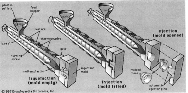
Figure 1: Simplified injection molding component and operations ... 13
Figure 2: Viscosity of pharmaceutical melts and polypropylene ... 17
Table 1: Reynolds numbers of diffferent hot extrusion system segments...18
Figure 3: Heat transfer rate vs Temperature for experimental set-up with fitted curve ... 21
Figure 4: Impurity area percent of active pharmaceutical ingredient at different temperatures and time spans ... 23
Figure 5: Hot extrusion molding system layout ... 30
Figure Al: Clamp Support Drawing ... 40
Figure A2: Clamp Backplate Drawing ... 41
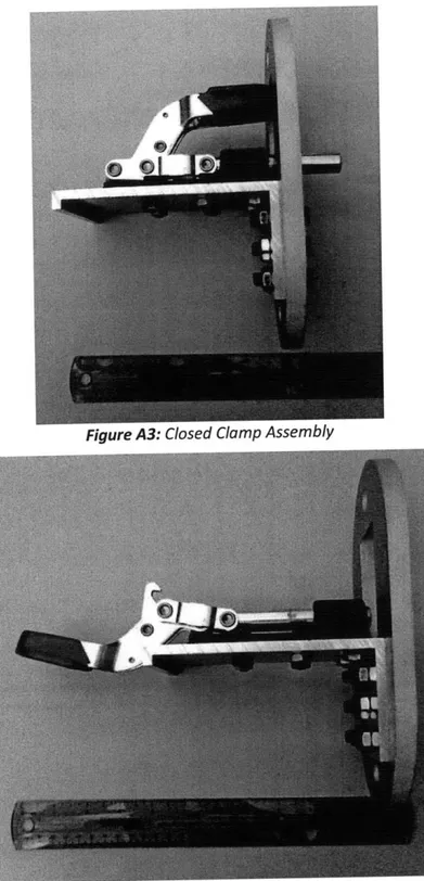
Figure A3: Closed Clamp Assembly...42
Figure A4: Open Clamp Assembly ... 42
Figure A5: Mold Cavity Backplate Drawing ... 43
Figure A6: Mold Cavity Backplate...44
Figure A7: Mold Cavity Drawing...45
Figure A8: Mold Cavity ... 46
Figure A9: Mold Core Drawing ... 47
Figure A10: Mold Core Backplate Drawing... 48
Figure All: Mold Core and Backplate Assembly ... 49
Figure A12: Hot Runner ... 50
Figure A13: Hot Runner Guide Drawing ... 51
Figure A14: Extruder Die Backplate Drawing ... 52
Figure A16: Extruder Die Drawing ... ... ....54
Figure A17: Extruder Die ... 55
Figure A18: Rail Drawing ...---...---... 56
Figure A19: Rail ...--... -..---....---...-- -- - .. 57
Figure A20: Hot Extrusion Molding System Assembly...58
Chapter 1: Introduction
Every year the pharmaceutical industry contribute to saving the lives of millions of
people from various diseases by developing and producing a variety of products that allows
many people suffering from illness to recover and lead productive lives.
The pharmaceutical industry is consistently near the top of the Fortune 500 survey of
most profitable industries. In 2006, global spending on prescription drugs was above $643
billion, despite a halt in growth in Europe and North America. The United States is the
industry's largest consumer with $289 billion in annual sales. The sales in the United States
were followed by the European Union and Japan. Emerging markets like China, Russia, Mexico
and South Korea grew 81 percent the same year.
Despite slowing profit growth, the pharmaceutical industry continues to be the most
profitable business in the U.S.
Much of the industry's achievements in the United States are attributed to the research
and development (R&D) of new drugs. However, this comes at a high price with the high proportion of revenue that needs to be reinvested into the firm. Although millions of
compounds are tested, it is not uncommon to find less than one hundred new prescription
Manufacturing is a substantial part of the total cost structure. According to some
estimates, these costs can be as high as 27-30% of sales for manufacturers of brand-name
pharmaceuticals, more than double the share of costs for research and development.1,2 In spite
of R&D largely focus on drug innovations or improvements, and much less is the focus on
solving the inefficiencies in manufacturing. The cost of bringing a new drug is projected to
require an investment of over $2 billion to progress from a laboratory idea to a successful
Chapter 2: Current Tablet Manufacturing Process
Pharmaceutical tablets are primarily produced in large batch operations, where
components are made in a single workstation before being moved on to the next one.
Traditional pharmaceutical manufacturing processes consist of pharmaceutical active
ingredients being synthesized in a chemical manufacturing plant. These ingredients are then
shipped to a manufacturing facility, often at another site, where milling and micronizing
machines pulverize substances into fine particles. These fine particles reduce bulk chemicals
into required sizes. Finished chemicals are later combined and processed further in mixing
machines, until when (in the case of tablets) they are pressed to their final shape. With
multiple interruptions, including transport to separate locations, each batch may take weeks to
produce. In addition, manufacturing design and scale-up for a new drug are very costly and
time-consuming.
Batch manufacturing procedures are useful in reducing the initial capital outlay by only
requiring a single production line that can be used with little modification to produce several
products. Batch manufacturing processes does have its fair share of disadvantages as well. The
stopping and restarting of machines is not time efficient, and results in additional operational
costs. Reconfigurations and output testing also contributes to additional downtime and slower
Chapter 3: Novartis-MIT Center for Continuous Manufacturing
The 10 year partnership, between Novartis and MIT, is working to develop new
technologies that aim to replace traditional batch production processes with continuous
manufacturing processes. When asked about the partnership Dr. Daniel Vasella, Chairman and
CEO of Novartis, said "This partnership demonstrates our commitment to lead not only in
discovering innovative treatments for patients but also in improving manufacturing processes, which are critical to ensuring a high-quality, efficient and reliable supply of medicines to
patients. Our collaboration with MIT, a worldwide leader in developing cutting edge
technologies, holds the promise to achieve a quantum leap in the production of
pharmaceuticals, a field which has received rather little attention in the past."
The Novartis-MIT Center for Continuous Manufacturing aims to benefit patients,
healthcare providers, and the pharmaceutical industry by:
* Accelerating the introduction of new drugs through efficient production processes
e Requiring the use of smaller production facilities with lower building and capital costs
" Minimizing waste, energy consumption, and raw material use
* Monitoring drug quality on a continuous basis rather than through post-production, batch-based testing
Chapter 4: Hot Extrusion Molding
One of the manufacturing alternatives being explored by the Novartis-MIT Center for
Continuous Manufacturing for the production of medicinal tablets is the direct injection of
tablets with a hot extrusion molding system. The main difference between hot and wet
extrusion is that hot relies on heat to melt the resin being used while wet extrusion relies on
the mixing of the resin with water and other agents that can be hardened into shape by drying.
Traditional injection molding machines produce parts from thermoplastic and thermosetting
plastic materials. Essentially the polymer is fed into a heated barrel, where it is mixed and
forced into a mold cavity where it solidifies as it cools and takes the shape of the mold cavity in
which it is being retained, until the part is ready to be ejected.
Injection molding machines have three basic components in order to achieve its
function. The first is the injection unit, often called the plasticator, which prepares the proper
plastic melt and transfers it into the second component, the mold. The third basic component is
the clamping system which opens and closes the mold. Injection molding machines all perform
certain necessary functions:
1. Plasticizing: heating, melting and mixing of the plastic in the injection unit,
2. Injection: controlled shot is injected from the plasticator into a close mold were it begins to solidify on the mold's cavity wall,
3. Packing: maintains injected material under pressure for a specified period of time to
compensate for decrease of volume during solidification and prevent backflow, 4. Cooling: cooling of the plastic in the mold until it is ready to be ejected,
5. Part Release: mold opens and part is ejected.
Once the part is successfully released the mold closes, and a new shot of melt is ready to be
introduced into the cavity.
Injection molding is a well understood and largely employed process which provides an
interesting alternative to the batch method. Although initially designed to perform as a
non-continuous extruder, advances in the process have opened the doors for injection molding to
run as a continuous process. For this project we are interested in a continuous manufacturing
process, but the differences in processing conditions and functional requirements of a
Chapter 5: Mixing criteria -Twin barrel screw
Before joining the project the team had acquired and began the use of a twin barrel
screw extruder to be used as the plasticator in the hot extrusion molding machine. The twin
barrel screw extruder is better suited to thoroughly mix the active pharmaceutical ingredient
with any excipient that might be used in the formulation of the tablets. The extruder used was
a Leistritz Twin Barrel extruder which is capable of generating pressures up to 2,030 PSI. This is
a much lower range than traditional injection molding plasticators, which generally operate on
pressures of 8,000 PSI and above. This meant that pressure drop calculations had to be
conducted to see whether if the filling/packing of the molds would be possible with the current
set-up.
Another big limitation in the use of a twin barrel screw instead of a traditional
reciprocating (single screw) screw is that there is no axial movement of the screw which acts as
a piston which allows for greater pressure control and can act as a shut off valve to regulate the
Chapter 6: Feasibility and Injection Pressure Requirement
As mentioned before, the first and most critical calculation needed to be employed was
the pressure drop calculations, to see whether the extruder could adequately force the material
through the runner and into the mold cavity. For this calculation, the Darcy-Weisbach
equation31 was used to obtain the pressure drop, Ap, as:
Ap - L pV2
D 2
where
f
is the friction factor, L and D are the respective lengths and diameters of different segments of the runner, p corresponds to the density of the active pharmaceutical ingredientand Vto its velocity.
The value of the friction factor changes depending if the flow is laminar or turbulent, so
the Reynolds number, Re, for the flow at the different segments of the system needed to be
calculated. The Reynolds number is expressed as: [41
Re = pVD (2)
where, p, corresponds to the material's viscosity.
The Density of the material was obtained by measuring the volume of a hand pressed
tablet made from the melt. The same tablet was then weighed, and the density was derived
The velocity of the active pharmaceutical melt was obtained by dividing the known mass
flow rate, m , of the extruder by the cross sectional area of each segment as shown
V
_mD2 I (3)
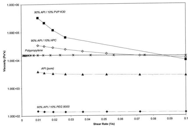
The viscosity was obtained from rheometry experimental setup conducted by Erin Bell and
shown in Figure 2. 1.00E+00 90% API / 10% PVP K30 1.OOE+05 90% API / 10% HPC Polypropylene 1.00E+04 -0 API (pure) 1.OOE+03 -90% API / 10% PEG 8000 1.OOE+02 0 0.01 0.02 0.03 0.04 0.05 0.06 0.07 0.08 0.09 0.1
Shear Rate (1Is)
Figure 2: Viscosity of pharmaceutical melts and polypropylene
For the different segments of the gate, runner and cavity the Reynolds numbers were
Table 1: Reynolds numbers of different hot extrusion system segments
The flows are always in the laminar regime, so the friction factor can be obtained from
[4]64
f
(4)
Using Equation 1 the total pressure drop was estimated to be 1117 psi, which is less than the
maximum pressure of the extruder.
Chapter 7: Temperature Considerations
One of the key challenges with the hot extrusion molding process of pharmaceutical
melts is that the material(s) used in the melt are much more expensive and need to be
meticulously controlled during production. Excess material in plastic injection molding is not a
problem since scraps can be collected and re-melted later, whereas in pharmaceutical
applications the melt can not be re-melted after solidifying since the active pharmaceutical
ingredient can degrade, and the dosage specifications can be lost.
Another problem we encounter is that there is a much narrower processing window in
order to prevent melt degradations. Unlike plastic injection molding, where the melt is
maintained at temperatures above 200*C until reaching the mold, we are limited by a much
lower temperature limit of about 950C before risking active pharmaceutical ingredient
degradation. This gives a window of approximately 10"C between melting temperature and
degradation temperature that has to be carefully controlled in order to avoid both the
premature solidification of the melt and the excessive heat degradation of the melt.
Additionally over exposure of the drugs to even 950C can also lead to active pharmaceutical
ingredient degradation, so the total time at a melted state needs to also be considered in the
Chapter 8: Cooling, Degradation and Coefficient Estimates
As mentioned before, there is a strong design concern of premature cooling in a hot
extrusion molding machine for pharmaceutical applications. Premature cooling can result in
clogging of the system or short shots when filling the molds.
For this reason cooling
calculations were needed to be conducted to quantify the potential for premature cooling.
Before being able to set any particular cooling models, some material thermal
parameters had to be obtained. Since little information was available about the material being
used some quick experiments to estimate the thermal diffusivity were conducted.
I insulated a hand formed tablet with Styrofoam leaving only both ends of the cylinder
uncovered. A temperature sensor was attached to both exposed ends. One end was then
placed on top of a heat plate, while the other was exposed to the ambient temperature. The
heat plate was incrementally raised up to 80"C, which is just under the melting temperature of
the material. At each temperature setting the temperature reading from each sensor was
recorded as well as the room temperature. The thermal conductivity, k, of a material can be
obtained from
51h
k =
Q.-
(5)
A(AT)
Where
Q
corresponds to the heat flux, h to height of the tablet, A to the cross-sectional area of
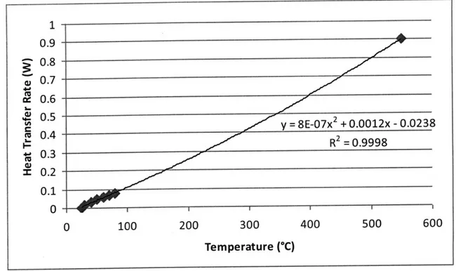
Since thermal conductivity is an intrinsic property we can make the assumption that for all the
measured values, k, should be constant, this restriction and the known heat flux at maximum
temperature was used to derive an expression for the heat flux at different temperature
settings. 1-0.9 x 0.8-0.7 S0.6 - 0.5-y= 8E-07x2 + 0.0012x - 0.0238 T 0.4 R2 = 0.9998 0.2 0.1 -O 0 100 200 300 400 500 600
Temperature (*C)
The line fit
then used
relation51
Figure 3: Heat transfer rate vs Temperature for experimental set-up with fitted curve
from Figure 3 was then use to back calculate the thermal conductivity, which was
to obtain the thermal diffusivity, a, of the material being study by using the
a=p
where c, is the specific heat. The specific heat can range between 0.84 and 2.30 J/(g -K).[7 (6)
The thermal conductivity was calculated using Equation 5 to be 0.893 ± 0.189 W/mK and
the thermal diffusivity was calculated using Equation 6 to be within the range of 2.6-10- m2/s
and 3.7-10~7 m2/s.
With these thermal parameters now available, the cooling time can now be obtained.
The centerline cooling times, te, and the average part cooling time, ta, are respectively [8]
= 0.173 h n 1.6023 ' (7)
(al 2 )I (T. - T,
ta =
0.
173h
2i
0.6916(
'(8)
" (an, 2 )I T - T,
where T,, Tw and Te correspond to melt temperature, mold wall temperature and ejection
temperature, respectively.
When inputting the calculated thermal diffusivity ranges from above into the cooling
equations the time for centerline to reach ejection temperature ranged from 7.1 to 9.9 s, and
time for average part to reach ejection temperature ranged from 5.7 to 7.9 s. This was an issue
since the cooling time was less than the actual filling time, 9 s, which indicated that the material
would prematurely cool clogging up the runner leading to the tablet.
Degradation is also another big concern, exposure to too high temperatures will damage
the active pharmaceutical ingredient, but if not melted enough we risk clogging the system by
premature freezing before reaching the cavity. Also the time exposed to heats even close to
exposure to heat at different intervals of time, the active ingredient was melted and kept at a
melted state for different intervals of time and was then allowed to cool until solidifying. The
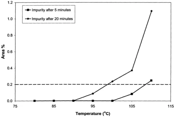
solid material was then tested to see the purity of the solid. Figure 4, obtained by Erin Bell, shows the area percent of the impurity in the active pharmaceutical ingredient, Y-axis, when
exposed to a set temperature, X-axis, for 5 and 20 minutes. The melt can stay at a temperature
between 85-1000C for 5 minutes without showing signs of degradation.
1.2
-U- Impurity after 5 minutes
1.0 - Impurity after 20 minutes
0.8-2
0.6- 0.4-0.2 --- --- ---0.0 -75 85 95 105 Temperature (*C)Figure 4: Impurity area percent of active pharmaceutical ingredient at different temperatures and time spans
The melt was observed to take between from 3.5 to 4.0 minutes to go from the feeding location
to the die of the extruder. So there is only about 1.0 to 1.5 minutes of time it can remain in the
Chapter 9: Hot Runner System
A hot runner system in injection molding differs from the more common cold runner
system in that the plastic is maintained heated at the melted state throughout by heated
components in addition to the plasticator. A typical hot runner system usually includes heated
manifolds and nozzles. The manifolds distribute the plastic entering the mold to the nozzles, which in tern meter it to the injection points in the cavities.
Hot runners have many advantages since they reduce material scrap, since there is no
need for a cold runner to freeze off since the nozzle takes care of directly injecting the melt to
the cavity. Since the cycle time of the mold is largely influenced by the cooling cycle,
minimizing the material that needs to cool down can increase the production output. As a
result hot runner systems are generally attributed with overall reduction in cycle times.
Injection time is also reduced since there is no wasted time in filling a cold runner, and, with no runner to interfere, parts molded with hot runner better lend themselves to automated
part removal. However, hot runner systems do require additional controls and add an
additional level of complexity in the design of an injection molding machine, but since the
cooling time is preventing the use of a typical cold runner system due to premature clogging, and since it provides a solution to the wasted resin material.
Since we were interested in producing a prototype, and are limited by the extruder
mass flow rate, it is not necessary to include a manifold for our system, which meant that the
pharmaceutical melt could flow from the extruder barrel directly to the nozzle which in turn fills
the mold cavity.
When selecting the nozzle to purchase for the application the main design consideration
criteria were:
. Large material Drocessing window - Since we are using pharmaceutical melts that are not traditionally injected molding, it was important to verify that it
operate with material property range.
" Nozzle tip and size - Medicinal tablets are small and require a nice surface
so the nozzle needs to leave a small impression on the tablet, and for
needs to be of small bore dimensions, under a millimeter.
" Nozzle length - Since the overall time in melted state is proportional t length of the flow channel, the longer the nozzle length the longer the n
exposed to high temperatures and risks decaying.
could
finish,
this it
o the
elt is
After looking for different hot runner nozzles a Synventive Series 03 501 open nozzle
was selected. This nozzle has an overall length of 56 mm, with a hot runner gate diameter of
0.6 mm. The WO2T gate tip had a large material processing window and allowed for shot sizes
as small as 100mg, it also is an open torpedo gate which helps in the control and finish of the
Chapter 10: Clamp Force
The clamping unit is one of the most critical components in the design of an injection
molding machine. It needs to be able to withstand the force that gets accumulated within the
molds. It also needs to be able to be controlled and operable.
When selecting an appropriate clamp for an application the clamp force,F,,,,,, is used
to determine the proper tool. Clamp force is determined as
Fiamp = Aprojec, Ap.
(9)
where Aprojected corresponds to the projected area of the cavity and Apm corresponds to the
maximum pressure which is limited by the extruder. This yields a clamp force of 200.2 lbs.
Although automation of the production is an eventual goal of the Novartis-MIT Center for
Continuous Manufacturing, it was decided to proceed with the purchase of a hand-operated
clamp. The reasoning behind this decision was that a programmable clamp is an additional
complexity that shouldn't be included in the proof of concept prototype that was going to be
built.
I purchased a De-sta-co 630-R line clamp for the machine. This model had holding
forces maximums of 2500 lbs and is a single line clamp which meant that the force can be
directly aligned on to the center of the mold to provide the right amount of support and
Chapter 11: Pressure Accumulation
Injection molding machines must be capable of handling and sustaining large pressures
inside, so safety precautions against pressure build-up within the machine should be in place to
prevent damaging the machine or injuring the operator. The extruder sets the limit of the
amount of pressure that can build up in the machine, since it stalls out at 2030 psi. The hot
runner was built to run with pressures of 8000+ psi so we don't expect any trouble with that
component. The clamp is rated to hold 2500 lbs, and is acting directly in line with the runner so
the extruder should stall out before risking any material failure.
However, the extruder stalling out is not an optimal solution if the system
over-pressurizes since, continuous restarting and cleaning of the machine is not aligned with the aim
of the project. For this reason a mechanical release was introduced into the system using a
heavy load die spring that can compress and release the pressure if it goes above a certain limit, limiting the stopping as a result of extruder stalling. The die spring also helps add preload to
Chapter 12: Additional Design Considerations and Material Selection
Since we are working with pharmaceutical grade material it is important that all the
components that come in contact with the melt wont compromise the purity of the melt. The
melt also has the characteristic of being rather sticky, of almost taffy-like texture, so surface
finishes are important to facilitate material ejection and removal. For these reasons all
components that come in direct contact with the melt are made from (304) stainless steel. The
parts that come in contact with the melt, in addition to the extruder and hot runner nozzle, are
the attachment die that connects the extruder to the hot runner nozzle and the mold
core/cavity.
Primary weight supporting materials, i.e rails, are to be made with steel to take
advantage of the high material strength for the relatively low cost. The remaining parts can be
fabricated from aluminum to keep overall weight of the attachments low and eases the
machining.
Proper alignment of the system is also important for the successful performance of the
system. Concentricity tolerances for this reason are important to be maintained and self
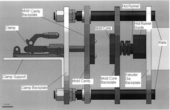
Chapter 13: Overall Design Layout
The hot extrusion injection molding system is incorporating the twin screw extruder, a
hot runner nozzle and a linear clamp, but these elements by themselves can not make a
complete machine by themselves. The molds have to be designed and fabricated to fit the hot
runner nozzle tip and to keep the cavity size consistent with the tablet weight specifications set
by Novartis. They also must align properly with respect to each other.
It would be counter cost effective and limit flexibility of the system if the molds are
rigidly attached as part of the machine. For this reasons the molds should be held in place by
back-plates that can be adjusted in location, and translate to allow the mold to open and close.
In order to allow the plates to slide and to support the weight of the machine, rails will be used
to support the back-plates. To help align the linear action of the clamp with the molds, the rails
will also support an additional back-plate to be where the clamp will be mounted.
The clamp-mold will be attached with a bolt that screws into the clamp plunger and is
attached to the mold cavity back plate to transfer the clamping force to the mold when closed.
On the other side the mold core is to constrain the hot runner nozzle with the use of the spring
die and a locking plate to prevent unwanted rotation. The hot runner nozzle is then linked to
Figure 5 shows the labeled overall design layout that was described in this chapter.
Additional information regarding the specifics of the different individual components is
presented in the next chapter.
Chapter 14: Individual Components
Pictures and CAD drawings are attached in the appendix for all the following parts.
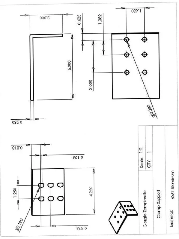
14.1 Clamp Support and Backplate
The before mentioned clamp is held in place by a combination of a 6061 aluminum
backplate that was also made on the waterjet to match the other pieces. This one is
held in place by a combination of think hex jam nuts and a nylon reinforced locknut on
the threaded side of the rail. The support is essentially a wide aluminum L-bracket with
through holes for attachment to the backplate and to the clamp. The holes are either
oversized or slotted to allow for minor adjustments for alignment in assembly.
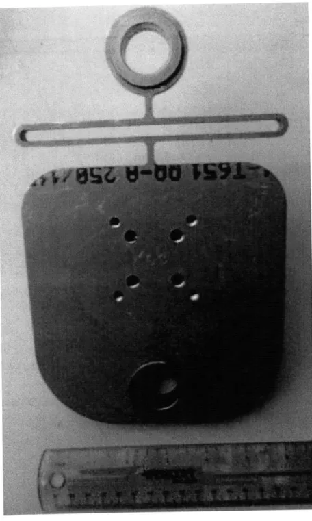
14.2 Mold Cavity Backplate
The mold cavity backplate is also made from 6061 aluminum using the waterjet.
This piece was designed with a flexure piece to allow for rail misalignment when sliding, and so that the locating pins in the molds can conform to be aligned with each other.
FEA was conducted on the flexure so that under 1% of the force applied of the clamp
the flexure could displace a minimum of 1/8 in either direction perpendicular to the
mold section. This piece is free to slide on the rails and is open / closed by a bolt
screwed into the clamp plunger.
14.3 Mold Cavity
The mold cavity is made from 304 Stainless Steel and together, with the core mold,
makes the second half of the cavity where the tablet is formed. This part contains the
male key that match up with the core's female ends for proper alignment. The male key
is made from steel dowel pins pressed fit into the mold. Like the mold core, the mold
cavity also is bolted down to the back plate using socket head cap screws.
14.4 Mold Core
The mold core is also made from 304 Stainless Steel. The tablet cavity is made so
that when matched up with the mold cavity it has the theoretic volume for a 300 mg
dose of the active pharmaceutical ingredient being molded. The opposite end of the
mold is the suggested dimensions for the cutout for the nozzle end. The mold is then
attached on to the back-plate with socket head cap screws that don't interfere with the
mold opening and closing. The mold core also contains female ends to where the mold
14.5 Mold Core Backplate
The mold core backplate is made from 6061 Aluminum using a waterjet to make
the shape and inner features. This piece is clamped on to the rails after being slid into
place. The center hole is used to keep the spring positioned in the system, the
combination of this with the core mold tube keep the spring properly constrained.
14.6 Extruder Die Backplate and Hot Runner Guide
The extruder die backplate is the last waterjetted part of 6061 aluminum in the
assembly. It bolts on to the extruder die in the extruder machine directly and locks on
to the rails using a pair of set screws. The hot runner guide is then bolted on to this
piece. The guide provides alignment support for the hot runner and can serve as a
mounting plate for additional customization.
14.7 Extruder Die
The extruder die was made out of stainless steel since it comes in contact with the
material. This attachment is responsible for the transfer in interior diameter between
the extruder barrel and the hot runner. It steps down the diameter with a 60 degree
angle to limit the pressure drop as a result of kinks, or the uncontrolled flow of
14.8 Rails
The 1117 steel rails are 1 inch in diameter. A flange was milled on to one end to
allow a place for the set screw to hold on to, while the other side was threaded so that
Chapter 15: Assembly Results and Discussion
The fabrication and assembly was tedious and required small modifications reflected in
the CAD drawings in the assembly. The hardest part to manufacture were the stainless steel
molds as a result of their small tolerance, and required the manufacturing of special tooling to
be able to make them. Type 304 stainless steel is very hard to work with, so if possible for
future work a softer grade stainless steel may be substituted if it meets the additional
specifications. Another large obstacle that we had to overcome resulted from the supplied hot
runner controller and its connections. There was confusion over the wiring documentation and
some connecter pieces were missing. After meeting with a representative the doubts were
cleared and the right plug was bought for the application.
The last issue in the build was interference. I overlooked travel path of the clamp
handle while opening and closing. It interferes with rail extending above it so modifications
have to be made to it so that it doesn't strike the rail or nuts while traveling. It may be possible
that the dowel pins might have to be faced down as well as there seems to be some gap
between the molds at a close state, which might result from the locating dowel pins coming in
contact with the backplate. After fine tuning alignment and running the machine we should
have a better idea of the severity of the potential issue, if any.
There is still some doubt about the capability of the furnished extruder to have the
exists, depending on the gravity of the situation, there are some ways to deal with it. First of
all, modifications to the API by blending it with other materials we can alter the properties of
the melt. If it is less viscous pressure drop as a result of friction can be reduced. The
interconnections between the different elements of the runner can add unwanted pressure
drops in the system as well. Another possibility is having an additional component between the
extruder and the hot runner system to increase the pressure of the system without affecting
Chapter 16: Conclusion
Throughout the course of completing this thesis I really learned the value of planning in
advance and allocating time to things going wrong and having unexpected, and not hard to
resolve obstacles. I also got a firsthand look as to how delivery and lead time can delay a
project. Overall I am glad I took part in this thesis. It allowed for me to take responsibility, make mistakes, and learn from those mistakes at an academic level, which I will soon not forget
References
1. Reinhardt UE. Perspectives on the pharmaceutical industry. Health Aff.
2001;20(5):1363-70.
2. Suresh P, Basu PK. Improving pharmaceutical product development and manufacturing:
impact on cost of drug development and cost of goods sold of pharmaceuticals.
Pharmaceutical Technology & Education Center, Purdue University, February 2006.
3. Denevers, N., (1970). Fluid Mechanics. New York: Harper Perennial.
4. J.P. Holman, Heat Transfer, McGraw Hill.
5. Halliday, David; Resnick, Robert; & Walker, Jearl(1997). Fundamentals of Physics
(5th ed.). John Wiley and Sons, INC., NY
6. Tipler, Paul A., Physics for Scientists and Engineers, 4th Ed., W.H. Freeman, (1999). 7. R.J. Crawford, Rotational molding of plastics
8. Rao, Natti S.; Schumacher, Gunter Design Formulas for Plastics Engineers (2nd Edition).
c%4 co 0 0 O 00 0 t ON 0
e
40'aa
I3 IC £L)KFigure Al: Clamp Support Drawing
0.50 T G o| Giorgioamefrllop Baracklt:olm Materia:6061 Al Scale: 1:2 QTY: (1)
Figure A3: Closed Clamp Assembly
s c-ale: 1:2
0
.25 0.so 4 x 0 0.28 TH R U ALL L_J 0 0.44 ~S 0-35 0 0.49 X 90+ , Near Sid e Giorgio Zamnpierollo 0 TY: (1) Mold Cavity Bcokp ate 4 x 10.201 THRU Material: 6061 A] 1/420 0.13 ~1.7S4
1~z
I IMINErip
Figure A6: Mold Cavity Backplate
SECTION
A-A
G iorgio Zamp ierollo Mold Cavity Sc ale:11 -T-: 4 x 0p 0.26 TH R U ALLL_j
g 0.44 T 0.35 D 0A9 X 90* Near Sid e 304 Stainless Steel-1
0.50 M-a teria1:Sx 0 0 2 6 THRUALL t--j 0 0 .4 W 0 2 . '10226 W E
=a
Gm
S
ECTIO0N
A-A
a
Scacle : 1: 1w Giorgio Zampierollo -. 7 0TY: (1)o
A
A
a Nold Core -rAIB
Mateial 402SfanlegMelSCALE2
:
1
0 .2. *4( '0 Maerial: .*08 $tainleu seelC
L
Giorgio Zampierollo Mold Core Backplate Material: Scale: 12 QTY: ) 6061 Al
0.12 x60 Nu :3 G~) 1.97 5 x 0.27 TH R UALL 2 0.44 T 0.35 -3.25 0.61 X9 0 Near Sid Scale: 1:1 Giorgio Zampierollo Scale- -QTY: (1) Hot RunnerGuide Material: 6061 Al
-') NO N CDA k RO.10 2,65 .0.50 2.75 -3050 Scale: 12 Giorgio Zampierollo -1:2 QTY: (1) xtrv d er Die Ba ckp la te Material: 6061 Al
A~
-a0 000 0.150 0.850 1.500SECTION
A-A
Sc alIe: 2:1 G iorgio Zampierollo Q TY:() Extru der Die Material: Stain less Steel (304)/4 -16 Thread Sc ale: 12 Giorgio Zampierollo QTY: (2) Rail Material: 111 7 Steel 1 .25