HAL Id: hal-01077040
https://hal.archives-ouvertes.fr/hal-01077040
Submitted on 23 Oct 2014
HAL is a multi-disciplinary open access
archive for the deposit and dissemination of
sci-entific research documents, whether they are
pub-lished or not. The documents may come from
teaching and research institutions in France or
abroad, or from public or private research centers.
L’archive ouverte pluridisciplinaire HAL, est
destinée au dépôt et à la diffusion de documents
scientifiques de niveau recherche, publiés ou non,
émanant des établissements d’enseignement et de
recherche français ou étrangers, des laboratoires
publics ou privés.
Bulk using an Iron Core
Bashar Gony, Kévin Berger, Bruno Douine, Michael Koblischka, Jean Lévêque
To cite this version:
Bashar Gony, Kévin Berger, Bruno Douine, Michael Koblischka, Jean Lévêque. Improvement of
the Magnetization of a Superconducting Bulk using an Iron Core.
IEEE Transactions on
Ap-plied Superconductivity, Institute of Electrical and Electronics Engineers, 2015, 25 (3), pp.8801005.
�10.1109/TASC.2014.2373494�. �hal-01077040�
Improvement of the Magnetization of a
Superconducting Bulk using an Iron Core
B. Gony, K. Berger, B. Douine, M. R. Koblischka, and J. Lévêque
Abstract—In most studies, the magnetization was carried out
without the iron core which is not the case in superconducting electrical applications. So in this paper we study the magnetization of YBCO bulk using a Pulsed Field Magnetization method in a symmetrical iron core. This iron core has the same structure as the iron core in an electrical motor. We have tested a new process of magnetization, firstly without the iron core and secondly with the iron core where we find an enhancement about 36 % of the trapped magnetic field. The contribution of the iron core in this improvement was discussed. These experimentations help to carry out the magnetization of the superconducting bulk in the superconducting motor or in the coupling applications.
Index Terms— High-temperature superconductors, Magnetic
cores, Magnetization, YBCO bulk.
I. INTRODUCTION
HE new kinds of High Temperature Superconductors (HTS) are promising materials for the permanent magnet applications [1]-[5]. The superconducting bulks can play many roles in the industrial applications: the application of magnetic bearings [6], [7], and the application of high power density rotating machines [8]-[12] because it can trap or shield a high value of magnetic fields [13]-[16].
The maximum value of remnant magnetic induction in a permanent magnet is less than 1.5 Tesla for the neodymium-iron-boron to date. By using the principle of trapping the magnetic field in a high critical temperature superconductor, it is possible to obtain 4 T on the surface of a superconducting bulk at 77 Kelvin, i.e. in liquid nitrogen, and also up to 17.6 T at 26 K [14].
Furthermore, increasing the induction value is very important. For example in an application that aims to transfer an effort, by increasing the value of the induction produced, we can increase the value of the magnetic energy in the air gap and thus the electromagnetic torque.
There are several methods of magnetization but we chose the most convenient method to execute in situ, it is PFM for "Pulsed Field Magnetization" method. The general principle of this method is a discharge a capacitor bank in a coil which we
This work was supported in part by the ANR project REIMS, ANR-10-BLAN-0944.
B. Gony, K. Berger, B. Douine, and J. Lévêque, are with the University of Lorraine, GREEN, Research Group in Electrical engineering and Electronics of Nancy - EA 4366, Faculté des Sciences et Technologies – BP 70239, 54506
Vandoeuvre-lès-Nancy Cedex, France, e-mail:
M. R. Koblischka is with the Institute of Experimental Physics, Saarland
University, Campus C63, 66123, Saarbrücken, Germany e-mail:
call the inductor. This discharge will generate a magnetic field pulse that will induce eddy currents and trapping a magnetic field in the superconductor bulk. This value of trapped magnetic field in the bulk depends on the critical current density Jc of the bulk, the size of the bulk, and the form of the magnetic field pulse applied on the bulk [17]-[21].
In the literature, the study of the magnetization was carried out without an iron core [22]-[23], which is not the case in most of the electrical applications. In the traditional motors and in the magnetic coupling applications, an iron core exists, so it is really useful to study the magnetization of a superconducting bulk by using an iron core.
In our knowledge, any detailed study was never carried out concerning the magnetization by a PFM method in a symmetrical iron core. So, we tested and compared the magnetization by PFM method with/ without a symmetrical iron core. We also discussed the results and the role of the iron core in the magnetization process.
First, we present the experimental means that we use for magnetizing. Then we present the new applied process of magnetization that we have studied for two cases: without iron core and with an iron core. Finally, we compare the results and show the contribution of the iron core in the magnetization.
II. EXPERIMENTAL MEANS
In this section, we present the superconducting bulk, the inductor, the two principles of magnetization with and without iron core, and a new process of magnetization. The work was carried out at the temperature of liquid nitrogen 77 K.
A. Superconducting bulk
We carried out all measurements on a superconducting bulk of YBCO which has a 31 mm of diameter, and 16.7 mm of height. The critical temperature of this superconducting bulk type is 92 K. This bulk does not have any holes inside, Fig. 1.
We always measure the magnetic field at the surface of superconducting bulk. We put two Hall sensors, HPP-NP from Arepoc, adapted to low temperatures: The first one is at the
T
center of the bulk surface, and the second is on the edge of bulk surface, at 10 mm from the first sensor. The distance between the active part of the sensor and the surface of the bulk is 0.5 mm.
B. Inductor
We use a copper coil as an inductor, Fig. 2, around the superconducting bulk due to its simple installation in industrial applications which has following parameters: 17 turns, an effective external diameter of 62 mm, an effective internal diameter of 32.6 mm, and an effective height of 20 mm. The section of the copper is about 9 mm² this section helps us to carry out some peaks of current with a current density more than 500 A/mm².
C. Magnetization circuit and operating mode
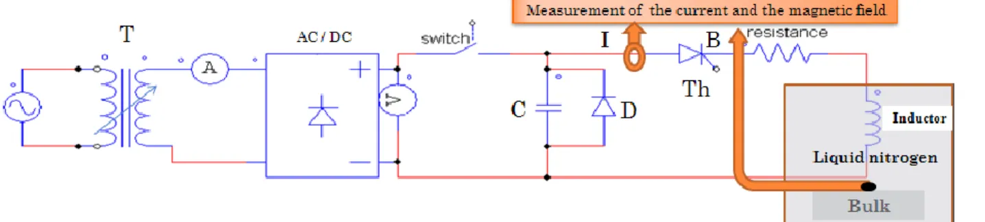
In order to apply the PFM method, we use an electrical circuit which consist of an autotransformer, a rectifier AC/DC, 24 capacitors in parallel for a total capacity of 79.2 mF, a thyristor, a diode, a coil, and some measuring devices, e.g. oscilloscope, voltmeter and amperemeter, see Fig. 3.
Basically, to carry out a magnetic field pulse, we should:
charge the capacitor with a proper level of tension;
discharge the capacitor in the copper coil. We have done the magnetization in 2 different cases:
1. Without iron:
The first experimentation part is carried out without any iron in the vicinity of the superconductor, Fig. 4.
2 . With iron:
The second one is carried out with an iron core which contains 200 sheets of isolated iron for decreasing the induced current in the magnetic core. Figure 5 shows a schematic of this E-I type iron core with the coil and the superconducting bulk inside it.
This magnetic circuit is almost the same as the one of a motor application like the synchronous motor proposed in
Fig. 6 where the superconducting bulks are at the places of permanent magnets. Field lines will flow in the air, iron, and superconducting bulk.
Fig. 2. The magnetization coil.
Fig. 4. The bulk YBCO inside its coil (left) and a sketch with the Hall sensors view (right).
Fig. 5. A schematic of the E-I type iron core used.
Fig. 6. A schematic of a motor with superconducting bulks.
Figure 7 shows the realized magnetic circuit that contains the magnetization coil, the superconducting bulk, and the two Hall sensors. The dimensions of this circuit magnetic are: 130 mm high, 150 mm of width and 74 mm depth. The air gap between the bulk and the iron core is about 7 mm.
III. PROCESS OF MAGNETIZATION
This process is used for the two cases of magnetization, with and without iron. This process of magnetization is a new kind of direct magnetization, i.e. the bulk doesn’t have any magnetic field when a higher magnetic field pulse is carried out. In the first part of this process, Fig. 8(a), one pulse is applied according to an initial charge voltage level of the capacitors and we save the maximum applied field and the trapped magnetic field in the bulk after 8-10 minutes. These values are saved for the two Hall sensors. Then we heat the bulk in order to remove the trapped magnetic field. Then we cool down the bulk in order to prepare it, and we apply a new magnetic pulse corresponding to an increase of 10 V applied to the capacitor bank. We repeat these steps: heating, cooling, applying a higher pulse, and we save the results until the maximum of trapped field is reached.
In the Figure 8(a), four increasing magnetic pulses are applied in phases A, B, C, and D. B , tA B ,tB B , and tC B are tD
the stable trapped magnetic fields after 8-10 min at the end of the pulses. Where C
t B > A , B, t t B B and D t B , so the charge voltage of the capacitors in phase C leads to the best magnetic pulse.
We repeat the pulse C, 3 to 6 times, for enhancing the trapped magnetic field without heating the bulk. As an example, in Fig. 8(b), C3 t B > C4 C2 , , t t B B and C1 t B , so the optimal pulse is C3 where we find the optimal trapped magnetic field
C3
t
B .
IV. RESULTS AND DISCUSSION
A. Without iron
The process of magnetization was applied in the superconducting bulk, and we found the optimal magnetic pulse by repeating the best pulse 4 times. The Figure 9 shows this last pulse: The current pulse has a maximum value of 4745 A, and a duration of 6 ms. The magnetic pulse has a maximum value of 1.60 T on the bulk surface center, and a 0.54 T of stable trapped magnetic field after 10 min. The maximum value measured by the second sensor at the edge is 1.12 T, and the stable trapped magnetic field is 0.39 T. These curves were taken from the oscilloscope, and filtered after that using Matlab.
Fig. 8. (a) First part of the magnetization process. Finding the optimal charge voltage of the capacitors that leads to the best trapped magnetic field. (b) Second part of the magnetization process. Enhancement of the trapped magnetic field.
-0.020 -0.015 -0.01 -0.005 0 0.005 0.01 0.015 0.02 0.025 0.03 0.5 1 1.5 2 Time (sec) Magne tic f lux den sity (T)
Optimal pulse without iron core
-0.02 -0.015 -0.01 -0.005 0 0.005 0.01 0.015 0.02 0.025 0.03-2000 0 2000 4000 6000 C u rr en t (A ) B center B edge Current
After 10 min, we obtain a stable trapped magnetic field of 0.39 T
After 10 min, we obtain a stable trapped magnetic field of 0.54 T
Fig. 9. Optimal magnetic and current pulse without any iron. Hall sensors are at the center and at the edge of the bulk.
B. With iron
By using the same process of magnetization, we find the optimal pulse by repeating the best pulse 5 times. The maximum value of the current is 2734 A. The sensor at the center and the sensor at the edge measure a maximum value of magnetic flux density of 1.43 T, and 1.79 T respectively. These sensors measure respectively a 0.85 T, 0.60 T of trapped magnetic flux density after 10 min, Fig. 10.
C. Comparison with/without iron
Figure 11 shows a magnetic field comparison between the magnetization with and without the iron core. We clearly see the enhanced trapped magnetic field with the iron core. We have an increasing of 36.5 % of trapped magnetic field at the center of the bulk when we do the magnetization inside the iron core, and 35 % at the edge of the bulk. In the case of the magnetization inside of the iron core, the maximum value of the current pulse for the optimal field is 43 % lower of its value without the iron core. As we know that the magnetic field without the bulk reaction in the air gap is proportional to the value of the current pulse, so we also decrease the applied magnetic field by 43 %. We remark that the duration of the two current pulses is nearly the same.
In order to study the contribution of the iron core magnetization, we have done this test: we have removed the iron core after the stabilization, at point A, and we observe the value of the trapped magnetic field, Fig. 12. After the new stabilization of the trapped magnetic field, we put again the superconducting bulk in the iron core, at point B, where we
find a new fast increase of the trapped magnetic field. After the new stabilization of the trapped field we remove the iron core a second time, at point C, where we found also a fast decrease of the field. We put the iron core a second time, at point D, and we can also observe a new increase of the trapped magnetic field in the same order of magnitude as for the previous case. 0 50 100 150 200 250 0 0.2 0.4 0.6 0.8 1 Time (min) T ra p p e d m a g n e ti c fi e ld ( T ) (T )
Influence of the iron core at the Trapped magnetic field
B center B edge
Remove the iron (C)
Zone II
Remove the iron (Point A)
Zone IV
Put the iron (B)
Zone III
Put the iron (D)
Zone V Zone
I
Fig. 12. The influence of the iron core on the trapped magnetic field in the superconducting bulk. The zones I, III, and V correspond to the evolution of the trapped magnetic field when the iron core is in place. Respectively, the zones II and IV correspond to the phases when the iron core is removed.
We can find that the decrease of the value of the trapped magnetic field between the level of the point A, and the level of the point B is due to the change of the magnetic field distribution applied on the superconducting bulk surface. This value is lost if we remove the iron, and we cannot reproduce it without a new magnetic pulse. When we put again the iron core in point B, the fast increase of the magnetic field cannot be explained by current density redistribution in the superconductor. Moreover, the difference between the value at the points B and C, is reproduced between the points C and D. So we can conclude that this change of trapped magnetic field between the points B and C, which is around 70 mT, is only due to the fact that a bigger part of the trapped magnetic flux is oriented in the direction of the iron core, the one that we measure. This phenomenon is reversible as for permanent magnets, and the stored energy in the YBCO bulk does not change.
As known, the trapped magnetic field can be increased by increasing the size of the YBCO bulk or by decreasing the cooling temperature. For the same size, at 30 K the trapped magnetic field can be more than 10 times the one at 77 K [13]. Some other experiments have to be done at lower temperature, in order to study the influence of the iron core on the magnetization process with higher trapped magnetic field.
V. CONCLUSION
Through our experimental results, we have proved than the magnetization of superconducting bulks using an iron core enhances the trapped magnetic field up to 36 % compared to classical process without iron. A simple coil around the bulk is needed. With the use of iron, we have also decreased the current of the optimal pulse by 43 %. A new phenomenon concerning the iron core contribution have been clearly shown and explained. This study will help to carry out the magnetization of bulk superconductors for the superconducting motors or magnetic coupling applications. -0.020 -0.015 -0.01 -0.005 0 0.005 0.01 0.015 0.02 0.025 0.03 0.5 1 1.5 2 Time (sec) Magne tic f lux den sity (T)
Optimal pulse with the iron core
-0.02 -0.015 -0.01 -0.005 0 0.005 0.01 0.015 0.02 0.025 0.03-1000 0 1000 2000 3000 Curr ent (A) B center B edge Current
After 10 Min, we obtain a stable trapped magnetic field of 0.6 T After 10 Min, we obtain a stable trapped magnetic field of 0.85 T
Fig. 10. Optimal magnetic and current pulse with the iron core. Hall sensors are at the center and at the edge of the bulk.
-0.020 -0.015 -0.01 -0.005 0 0.005 0.01 0.015 0.02 0.025 0.03 0.5 1 1.5 2 Time (sec) Magne tic f lux den sity (T)
Comparison between two optimal pulses whith/whithout iron core
-0.02 -0.015 -0.01 -0.005 0 0.005 0.01 0.015 0.02 0.025 0.03-2000 0 2000 4000 6000 Curr ent (A) Current B center
Whit iron core Whithout iron core
Whit iron core
Whithout iron core
Fig. 11. Comparison the optimal magnetic pulses with and without iron core, and its currents.
REFERENCES
[1] A. M. Campbell and D. A. Cardwell, “Bulk high temperature superconductors for magnet applications”, Cryogenics, vol. 37, pp. 567-575, 1997.
[2] N. Yamachi, T. Nishikawa, M. Tomita, K. Sawa and M. Murakami, “Measurements of magnetic fields of levitated bulk superconductors”, Physica C, vol. 378, pp. 877-882, 2002.
[3] M. Sander, “Cryo-permanent magnets-geometry, magnetization and cost issues’’, IEEE trans. Appl. Supercond., vol. 15, pp 1431-1434, 2005. [4] T. H. Habisreuther, D. Litzkendorf, O. Surzehenko, M. Zeisberger, R. Muller, J. Riches, S. Scauroth, J. Dellith and W. Gawalek “Requirements on melt-textured Y-Ba-Cu-O for the use in magnetic bearings or electric motors” IEEE Trans. Appl. Supercond,. vol. 11, pp. 3501-3504, 2001.
[5] P. Vanderbemden, Z. Hong,T. A. Coombs, M. Ausloos, N. Hari Babu, D. A. Cardwell and A. M. Campbell, “Behavior of bulk high-temperature superconductors of finite thickness subjected to crossed magnetic fields: experiment and model”, Supercond. Sci. Technol., vol. 17, 14 pages, 2007. [6] T.A. Coombs, A. M. Campbell, R. storey and R. Weller, “Superconducting magnetic bearings for energy storage flywheels”, IEEE trans. Appl. Supercond., vol. 9, pp. 968-971, 1999.
[7] T.M. Mulcahy, J.R. Hull, K. L. Uherkal, R. G. Abboud and J.J. Juna, “Test results of 2-kwh flywheel using passive pm and HTS bearings”, IEEE Trans. Appl. Supercond., vol. 11, pp. 1729-1732, 2001.
[8] M. D. McCulloch and D. Dew-Hughes, “Brushless ac machines with high temperature superconducting rotors", Mater. Sci. Eng. B, vol. 53, pp.211-215, 1998.
[9] B. Oswald, K. J. Best, M. Setzer, M. Soll, W. Gawalek, A. Gutt, L. Kovalev, G. Krabbes, L. Fischer and H. C. Freyhardt, “Reluctance motors with bulk HTS material”, Supercond. Sci. Technol., vol. 18, s24, 2005. [10] A. Alvarez, P. Suarez, D. Caceres, X. Granados, X. Obradors, R. Bosch, E. Cordero, B. Perez, A. Caballero and J. A. Blanco, “Superconducting armature for induction motor of axial flux based on YBCO bulks”, Physica C, vol. 372-376, pp. 1517-1519, 2002.
[11] M. Qiu, H. K. Huo, Z. Xu, D. Xia, L. Z. Lin and G.M. Zhang “Technical analysis on the application of HTS bulk in permanent magnet motor", IEEE Trans. Appl. Supercond., vol. 15, pp. 3172-3175, 2005.
[12] G. Stumberger, M. T. Aydemirt, D. Zarko, T. A. Lipo, “Design of a linear bulk superconductor magnet synchronous motor for electromagnetic aircraft launch systems’’, IEEE trans. Appl. Supercond, vol. 14, pp. 54-62, 2004.
[13] M. Tomita and M Murakami “High-temperature superconductor bulk magnets that can trap magnetic fields of over 17 tesla at 29 K”, Nature, vol. 421, pp. 517-520, 2003.
[14] J. H. Durrell, A. R. Dennis, J. Jaroszynski, M. D. Ainslie, K. G. B. Palmer, Y-H. Shi, A. M. Campbell, J. Hull, M. Strasik, E. E. Hellstrom, D. A. Cardwell, “A Trapped Field of 17.6 T in Melt-Processed, Bulk Gd-Ba-Cu-O Reinforced with Shrink-Fit Steel”, Supercond. Sci. Technol., vol. 27, 082001, 2014.
[15] M. Eisterer, S. Haindl, M. Zehetmayer, R. Gonzalez-Arrabal, H. W. Weber, D. Litzkendorf, M. Zeisberger, T. Habisreuther, W. Gawalek, L. Shlyk and G. Krabbes “Limitations for the trapped filed in large grain YBCO superconductors”, Supercond. Sci. Technol, vol. 19, s530, 2006.
[16] M. Muralidhar, M. R. Koblischka and M. Murakami “Improvement of critical current densities in bulk superconductors of the 123-Type”, Physica stat. sol., vol. 171, pp. R7-R8, 1999.
[17] B. Douine, F. Sirois, J. Leveque, K. Berger, C.H. Bonnard, T. Hoang, and S. Mezani “A new direct magnetic method for determining in bulk superconductors from magnetic field diffusion measurements’’, IEEE trans. Appl. Supercond., vol. 22 (3), 9001604, 2012.
[18] G. P. Lousberg, M. Ausloos, P.H. Vanderbemden and B Vanderheyden “Bulk high-Tc superconductors with drilled holes: how to arrange the holes to maximize the trapped magnetic flux”, Supercond. Sci. Technol., vol. 21 (2), 025010, 2008.
[19] L. Chen, Y.S. Cha, H. Claus, H. Zheng, B. W. Veal, and F. Z. Peng, “Optimization of pulsed-current profile for magnetizing high Tc bulk YBCO superconductors“, IEEE transactions on plasma science, vol. 34, pp. 1702-1708, 2006.
[20] K. Berger, J. Leveque, D. Netter, B. Douine, A. Rezzoug, “Influence of Temperature and/or Field Dependences of the E−J Power Law on Trapped Magnetic Field in Bulk YBaCuO”, IEEE trans. Appl. Supercond, vol. 17 (2), pp. 3028-3031, 2007.
[21] B. Gony, R. Linares, Q. Lin, K. Berger, B. Douine, and J. Leveque, “Influence of the inductor shape, and the magnetization processes on a trapped magnetic flux in a superconducting bulk”, Physica C, vol. 503, pp. 1-6, 2014.
[22] U. Mizutani, T. Oka, Y. Itoh, Y. Yanagiy, M. Yoshikawa and H. Ikuta,
"Pulsed-field magnetization applied to high-Tc superconductors”, Appl.
Supercond., vol. 6, pp. 235-246, 1998.
[23] L. Chen, Y. S. Cha, H. Claus H. Zheng, B.W. Veal and F.Z. Peng, “Optimization of pulsed-current profile for magnetizing high Tc bulk YBCO superconductors”, IEEE Transactions on Plasma Science, Vol. 34, pp. 1702-1708, 2006.