Conceptual Design of Nuclear-Geothermal Energy Storage Systems for
Variable Electricity Production
ARCHIVES
AASSACGJC'ETTS INST[TUTE
OF CHNOLOGY
By
Youho Lee
009))
U, uBRARIES
B.S, Nuclear and
Quantum
Engineering
(2009)----Korea Advanced Institute of Science and Technology
SUBMITTED TO THE DEPARTMENT OF NUCLEAR SCIENCE
AND ENGINEERING
IN PARTIAL FULFILLMENT OF THE REQUIREMENTS FOR THE DEGREE OF
MASTER OF SCIENCE IN NUCLEAR SCIENCE AND ENGINEERING
AT THE
MASSACHUSETTS INSTITUTE OF TECHNOLOGY
JUNE 2011
@ 2011 Massachusetts Institute of Technology
All rights reserved
Author
Youho Lee
Department of Nuclear Science and Engineering
2011.5.13
Certified by
Certified by
AAh
Charles W. Forsb6g
Professor of Nuclear Science and Engineering
Thesis Supervisor
Michael J. Driscoll
Professd&Vmeritus of Nuclear Science and Engineering
Thesis Reader
Accepted by
Mujid S. Kazimi
TEPC &rofessor of Nuclear Engineering
Chair, Department Committee on Graduate Students
ACKNOWLEDGEMENTS
This work was supported by the Idaho National Laboratory (INL) through the project Hybrid Systems for Process Integration and Dynamic Studies. I would like to thank the INL for the project support and the Korea Institute of Energy Technology Evaluation and Planning for the fellowship for my studies in the United States.
I would like to thank my advisor, Prof. Forsberg, for his guidance and support throughout this study. His
creative ideas and initiatives have inspired my learning at MIT. I feel very fortunate to have had a chance to work with Prof. Driscoll who has greatly supported and helped this study. From him, I learned attitudes for lifelong learning. I appreciate Dr. Bernard of the MIT Reactor for giving me valuable advice and help for my graduate studies in general. I am also grateful for my undergraduate advisor Prof. Hee Cheon No, Prof. Jeong Ik Lee and Dr. Sung Joong Kim for giving me advice to successfully make a transition from my undergraduate studies in Korea to graduate studies in the USA. Although I cannot list the names of everyone who helped my studies in this limited space, I do remember and appreciate every single help and advice I have received.
I would like to thank my parents for their unconditional love and support throughout my life. No amount
of success in my life would be possible if not for them. Finally, I thank God for becoming the meaning of my academic endeavor.
TABLE OF CONTENTS
ABSTRACT...3
ACKNOWLEDGEMENTS...5
TABLE OF CONTENTS...7
LIST OF FIGURES...10
LIST OF TABLES...13
NOMENCLATURE...14
1. Introduction...17
1.1 Implication of Electricity Storage...17
1.2 Current Status of Energy Storage & Need for Seasonal Storage...18
1.3 Objective of the Thesis...19
1.4 Organization of the Thesis...20
1.4.1 Chapter 2: The Concept of a Nuclear-EGS Storage System...20
1.4.2 Chapter 3: Nuclear-EGS System Models...
20
1.4.3 Chapter 4: Design of Nuclear EGS System...20
1.4.4 Chapter
5:
Economic Analysis of Nuclear-EGS System...21
2. The Concept of a Nuclear-EGS Storage System.
2 .1 Introduction ...
22
2.2 The System C oncept...22
2.2.1 Engineering Concept: Coupling Between Nuclear Power Plant-...22
Reservoir-Geothermal Power Plant
2.2.2 Economics Concept -Selling Electricity at Higher Peak Power Prices...24
2.3 Technical Options and Targets...25
2.3.1 Nuclear Power Plants...25
2.3.2 Geothermal Power Plants...
29
2.3.3 Geothermal Energy Conversion Systems...
33
2.3.5 D epth ...
36
2.3.6 Underground Stimulation-Increasing Rock Permeability...38
2.4 C onclusion ... 42
3. Nuclear-EGS System Models...44
3 .1 Introduction ... 44
3.2 Principles of Reservoir Modeling...44
3.3 Analytical Underground Reservoir Model Development...45
3.3.1 Reservoir Heat Transfer Modes...45
3.3.2 Reservoir Temperature Modeling...47
3.3.3 Reservoir Pressure Drop Modeling...48
3.3.4 Reservoir Heat Loss Modeling...50
3.3.5 Reservoir Water Loss Modeling...51
3.4 CFD Simulation of Reservoir Model...53
3.4.1 Governing Equations in the FLUENT Model...54
3.4.2 Geometry Description...59
3.4.3 Boundary Condition Description... 62
3.5 Results of Reservoir Models and Point Model Development...63
3.5.1 Thermal Front Velocity...65
3.5.2 Storage Size... 78
3.5.3 C ycle Periods... 80
3.5.4 Conductive Heat Losses...82
3.5.5 Pressure Drop...94
3.5.6 W ater Loss... 96
3.5.7 Geothermal Power Plant Performance...99
3.5.8 Reservoir Temperatures...103
3.5.9 Operating Conditions...104
3 .6 C onclusion ... 107
4. Design of Nuclear EGS System...108
4 .1 Introduction ... 108
4.3 Design Study...111
4.3.1 Engineering M ap...
111
4.3.2 Sensitivity Studies for Engineering Performances of the Nuclear-...121
EGS Energy Storage System
4.3.2.1 L/R Ratio Effect...122
4.3.2.2 Maximum Reservoir Temperature Effect...125
4.3.2.3 Porosity Effect...129
4.3.2.4 Permeability Effect...131
4.3.2.5 Rock Volumetric Thermal Capacity Effect...134
4.3.2.6 Cycle Period Effect...138
4 .4 C onclusion ...
14 1
5. Economic Analysis of Nuclear-EGS System ...
143
5 .1 Introduction ...
143
5.2 G rid C haracteristics ...
143
5 .3 E lectricity Price...146
5 .4 E lectricity C ost...148
5.5 Economic Benefits of Nuclear-EGS System...155
5 .6 C onclusion ...
163
6. Summary and Recommendations for Future Work...164
6.1 Sum m ary of Study...164
6.2 Recommendations for Future Work...168
REFERENCES...170
APPENDIX A: MATLAB Script for Engineering Map Calculations...172
APPENDIX B: MATLAB Script for Design Parameter Sensitivity Tests...177
List of Figures
Fig.1-1 New England Electricity Demand Variation: A:Hourly B:Daily C:Weekly(Seasonal)...17
Fig. 1-2 Capabilities of Energy Storage Technologies ... 19
Fig.2-1 Conceptual Diagram of Nuclear-Geothermal Energy Storage System...23
Fig.2-2 Average Monthly Retail Price of Electricity in the USA, 2007 through 2009...24,147 (A: Different Sectors, B: All Sectors Averaged) Fig.2-3 Two Different Charging Options for a LWR (PWR)...28
Fig.2-4 Types of Geothermal Energy Generation Projects...31
Fig.2-5 EGS Production System Scheme ... 32
Fig.2-6 Cost Break Down for a 50MW Conventional Flashed Hydrothermal Power Plant ... 32
Fig.2-7 Schematics of EGS Power Conversion Systems: ... 34
(a) a Basic Binary Power Plant; (b) a Single Flash Power Plant; (c) a Triple-Expansion Power Plant for Supercritical EGS Fluids Fig.2-8 Perm eability of D ifferent Rocks...36
Fig.2-9 Completed oil, gas, and geothermal well costs as a function of depth in 2004 US$...38, 151 Fig.2-10 Concept of H ydraulic Fracture...39
Fig.2-11 Concept of Block Caving... 41
Fig.3-1 1-D Transient Temperature Profile in Underground Storage A: Reality, B: Model...48
Fig.3-2 Transient Heat Conduction Model for a semi-infinite solid...50
Fig.3-3 Reservoir W ater Leakage M odel...52
Fig.3-4 Temperature Profile of an Underground Storage Reservoir during a Charging Period...58
Fig.3-5 Geometry Illustration of CFD Reservoir Model...59
Fig.3-6 Geometry Illustration of CFD Reservoir Model with Boundary Conditions...60
Fig.3-7 Transient Temperature Contour During a Charging Process: Case No.1, Length =1000m,...67
Radius= 250m: Time= 60 Days Fig.3-8 Transient Temperature Contour During a Charging Process: Case No.1, Length =1000m,...67
Radius= 250m: Time= 140 Days Fig.3-9 Transient Temperature Contour During a Charging Process: Case No.1, Length =1000m,...67
Radius= 250m: Time=220 Days Fig.3-10 Transient Temperature Contour During a Charging Process: Case No.1, Length =1000m,...68
Radius= 250m: Time= 250 Days Fig.3-11 Transient Temperature Contour During a Charging Process: Case No.1, Length =I000m,...68
Radius= 250m: Time= 280 Days Fig.3-12 Transient Temperature Behavior for the Reservoir Case No.1...69
Fig.3-13 Transient Temperature Contour During a Charging Process: Case No.1: Length=300m,...72
Radius=250m: Time=30Days Fig.3-14 Transient Temperature Contour During a Charging Process: Case No.1: Length=300m,...72
Radius=250m: Time=60Days Fig.3-15 Transient Temperature Contour During a Charging Process: Case No.1: Length=300m,...73
Radius=250m: Time=90Days Fig.3-16 Transient Temperature Contour During a Charging Process: Case No.1: Length=300m,...73
Radius=250m: Time=120Days Fig.3 -17 Transient Temperature Contour During a Charging Process: Case No.1: Length=300m,...73
Radius=250m: Time=150Days Fig.3-18 Transient Temperature Behavior for the Reservoir Case No.16...74
Fig.3-19 Thermal Front Velocity Comparisons for Ten Different Reservoirs: Charging Processes...77
Fig.3-20 Thermal Front Velocity Comparisons for Ten Different Reservoirs: Discharging Processes...77
Fig.3-22 Comparison for Conductive Heat Loss Rates Obtained from CFD Simulation and...82
Analytical Modeling Fig.3-23 Transient Temperature Records at Fluid Inlet and Outlet: Case 11...84
Fig.3-24 Transient Average Heat Fluxes at the Lateral Surface of Reservoir: Case 11...85
Fig.3-25 Temperature Contour of Reservoir Case 11- A: End of 1s' Cycle B: End of 1 0 th Cycle...86
Fig.3-26 Peak Average Surface Heat Fluxes for Loss and Gain...88
Fig.3-27 Average Surface Heat Rate at the Lateral Surface of the Reservoir: Cycles of No.11...89
Reservoir Length: 600m, Diameter: 187.5m Fig.3-28 Amount of Net Conductive Thermal Energy Loss for Reservoir Case 11...90
with Heat Storage Capacity of 1.1 GW(th)-year Fig.3-29 Amount of Net Conductive Thermal Energy Loss for Reservoir Case 11...91
Fig.3-30 Fractional Thermal Energy Loss for Three Different Reservoir Sizes...92
Fig.3-31 Temperature Dependent W ater Viscosity... 94
Fig.3-32 Time Dependent Pressure Drop during a Charging Process: Reservoir Case#1...95
Fig.3-33 Water Leakage Rate of a Nuclear-Geothermal Reservoir...97
Fig.3-34 EGS Electricity Conversion Performance as a Function of the Minimum Temperature...101
Fig.3-35 Schematic Diagram of a Charging Process...105
Fig.3-36 Operating Conditions at Different Points in the System...105
Fig.4-1 Operating Conditions at Different Points in the System...109
Fig.4-2 Energy Storage Performance Metrics of Nuclear-EGS System: Thermal Storage size,...113
Electricity Storage Size, Mass Flow Rate, and Charging Heat Rate (average) Fig.4-3 Design Limit Imposed by Maximum Average Charging Heat Rate at 6000 MWth...114
Fig.4-4 Charging Effort Performance Metrics of Nuclear-EGS system: Average Pressure Drop,...116
Mass Flow Leakage Ratio, Average Pumping Power, Fraction of Pumping Power Fig.4-5 Round Trip Storage Efficiency of Nuclear-EGS System...119
Fig.4-6 System Storage and Geo-Fluid Circulation Effort Performance Metrics with Varying...123
L/R Ratio (1) : Electricity Storage size, Average Pressure Drop, and Average Pumping Power Fig.4-7 System Efficiency Performance Metrics with Varying L/R Ratio (2): Fraction of Pumping...124
Power, Mass Flow Rate Leakage ratio, and Round Trip Cycle Efficiency of Storage System Fig.4-8 System Storage Performance Metrics with Varying Maximum Reservoir Temperature (1) :. 126 Thermal Storage Size, Electricity Storage Size, Charging Heat Rate Fig.4-9 System Geo-Fluid Circulation Effort Performance Metrics with Varying...127
Maximum Reservoir Temperature (2) : Average Pressure Drop, Required Mass Flow Rate, Average Pumping Power Fig.4-10 System Efficiency Performance Metrics with Varying... ... 128
Maximum Reservoir Temperature (3) :Fraction of Pumping Power, Mass Flow Leakage Ratio, Round Trip Cycle Efficiency of Storage System Fig.4-1 1 System Storage Performance Metrics with Varying Porosity (1) : Thermal Storage Size,...130
Electricity Storage Size, Charging Heat Rate Fig.4-12 System Storage and Geo-Fluid Circulation Effort Performance Metrics with Varying...132
Permeability (1) : Electricity Storage Size, Average Pressure Drop, and Average Pumping Power Fig.4-13 System Efficiency Performance Metrics with Varying Permeability (2):...133
Fraction of Pumping Power, Mass Flow Rate Leakage Ratio, and Round Trip Cycle Efficiency of Storage System Fig.4-14 System Storage Performance Metrics with Varying Volumetric Thermal Capacity of Rock...135
(1) :Thermal Storage size, Electricity Storage Size, Charging Heat Rate Fig.4-15 System Geo-Fluid Circulation Effort Performance Metrics with Varying Volumetric...136
Thermal Capacity of Rock (2) : Average Pressure drop, Required Mass Flow Rate, Average Pumping Power
Fig.4-16 System Efficiency Performance Metrics with Varying Thermal Capacity of Rock (3) :...137
Fraction of Pumping power, Mass Flow Leakage Ratio, Round Trip Cycle Efficiency of Storage System
Fig.4-17 System Storage and Geo-Fluid Circulation Effort Performance Metrics with Varying Cycle... 139 Period (1) : Electricity Storage Size, Average Pressure Drop, and Average Pumping Power Fig.4-18 System Efficiency Performance Metrics with Varying Cycle Period (2):...140
Fraction of Pumping Power, Mass Flow Rate Leakage Ratio, and Round Trip Cycle Efficiency of Storage System
Fig.5-1 Total Electricity Net Generation in the USA 2007 through 2009 and Comparison...144 with Sinusoidal Best Fit
Fig.5-2 Sinusoidal Demand Curve with Period % Year of New England...146
Fig.5-3 Levelized Cost Break-Down of Two Different Capacity Factors for EGS and Gas Turbines....154
Fig.5-4 An Illustration for a Simplified Grid Portfolio of Nuclear, EGS and Gas Turbine...155
Fig.5-5 Calculation Procedure for the Total Costs for Different Base Load Levels...156 Fig.5-6 New England Grid Characteristics as a Function of New Base Load Level:...159
A-Total Electricity Cost, B-Annual Average Electricity Supply Portfolio, Electricity Storage Size Fig.5-7 Sensitivity Studies of Economic Benefits of Nuclear-EGS System as a Function of:...162
List of Tables
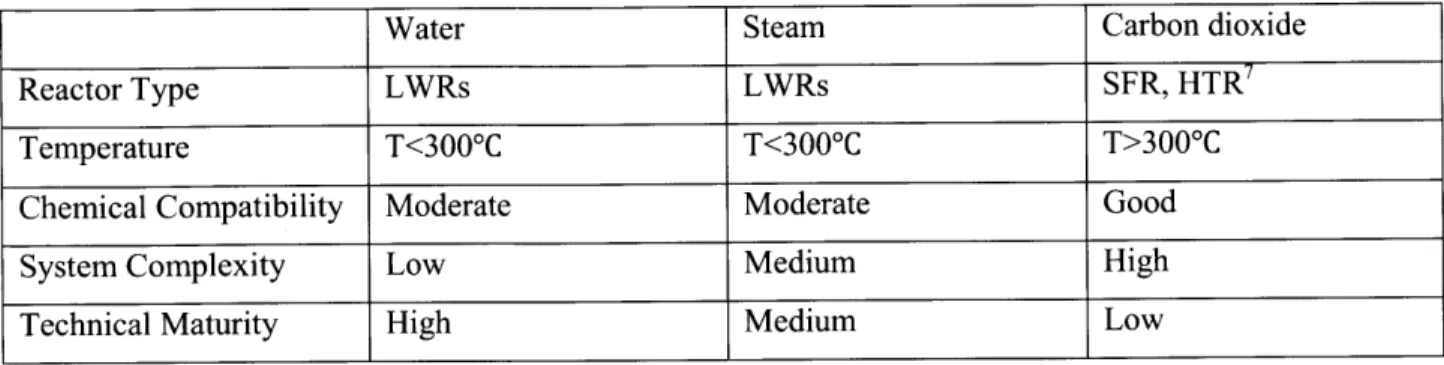
Table 2-1 Summary of Nuclear Reactor Options and Charging Fluids for the Nuclear Power Plant-...27
Reservoir Coupling Table 2-2 Summaries of Representative Temperatures for a PWR and BWR...29
Table 2-3 Summary of Technical Options for Nuclear Geothermal Energy Storage System...43
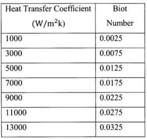
Table 3-1 Biot Number of a Representative Nuclear-EGS Underground Reservoir...46
Table 3-2 Reservoirs Tested in FLUENT Simulations... 64
Table 3-3 Obtained Thermal Front Velocities Using Analytical Model... 66
Table 3-4 Analytical & CFD Obtained Thermal Front Velocities...76
Table 3-5 Operational Parameters Tested for Reservoir Simulation: Case 11...84
Table 3-6 Design Features of Tested Reservoirs for Fractional Thermal Energy Loss...92
Table 3-7 Fixed Parameters Used for Fig.3-33...97
Table 3-8 Reference Geothermal Power Plant...100
Table 3-9 Comparisons of Direct and Indirect Geothermal Power Plants...102
Table 3-10 Two Different Charging Systems Illustrated in Fig.3-36...104
Table 4-1 Constants Used for Mapping Performance Metrics...111
Table 4-2 Performance Metrics of the Reference Nuclear-EGS Energy Storage Systems...120
Table 4-3 Test Matrix of Sensitivity Studies...121
Table 4-4 Summary of Design Variation Effects...141
Table 5-1 Values Used for the Levelized Electricity Cost Evaluation...149
Table 6-1 Summary of Technical Options for Nuclear Geothermal Energy Storage System...165
Table 6-2 Performance Metrics of the Reference Nuclear-EGS Energy Storage Systems...166
Nomenclature
Abbreviations
BWR Boiling Water Reactor
CFD Computational Fluid Dynamics
EC Energy Conversion
EGS Enhanced Geothermal System HTR High Temperature Reactor
Engineering Terms L, Length [m] t, Time [sec] k, Thermal conductivity [w/m 'C] T, Temperature ['C or K] A, Area [m]
rn, Mass flow rate [kg/sec]
ri, Efficiency [-]
v, Fluid velocity [m/sec]
P, Pressure [Pa]
t, Viscosity [Pa.s]
d, Diameter [in] D, Burial depth [m]
ip, Fractional Energy Loss [-]
1IDarcy =9.869233E-13 m2 LWR MIT NE PWR ISO
Light Water Reactor
Massachusetts Institute of Technology
New England
Pressurized Water Reactor
Independent System Operator
V, Volume [M3] M, Mass [kg]
Bi, Biot number [-]
K, Permeability [Darcy']
H, Enthalpy [J/kg]
C,, Specific heat [J/kg0C]
h, Heat transfer coefficient [w/m2 C]
u, Thermal front velocity [m/sec]
AP, Pressure drop [Pa]
a, Thermal diffusivity [m2
/sec]
R, Radius [in]
E, Energy [J]
At, time interval [sec]
Economic Terms2
L, Plant Capacity [-] p, Annual Fixed Charge Rate [1/year]
r, Tax Fraction [-] rb, Rate of Return on Bonds [-]
rs, Rate of Return on Equity [-] b, Debt Fraction [-]
- Overnight Specfic Captial Cost of Plant [$/kW] y Annual Rate of Monetary Inflation [1/year]
c Time required to construct plant [year] T Prescribed useful life of plant [year]
- Specific Operating and Maintenance Cost as of Start of Operation [$/kW/Year] fo Fossil Fuel Cost [$/mmBTU]
Subscript 3
c characteristic in inlet
f fluid s sold, or surface4
oo bulk sup superficial
surr surrounding res reservoir
avg average hyd hydraulic static
mag magnitude eff effective
ref reference
Superscript
- average - vector
2 Distinctions be made with the engineering terms. The economic terms restrictively appear in Chapter 5.
3 Subscripts for a complete word are not listed here
CHAPTER 1
INTRODUCTION
1.1 Implications of Electricity Storage
The need for energy storage is ubiquitous. Spanning from a small battery in a cell phone to a gigantic dam, energy storage technologies vary as much in their size as their applicability. Nevertheless, electricity storage technologies have one thing in common: potential for significant environmental, economic and energy diversity benefits. In general, the benefits of energy storage can be specifically divided into the following four categories: matching electricity supply to load demand, providing backup power to prevent outages, enabling renewable technologies, and power quality control.
Among the benefits listed above, the most significant one would be matching electricity supply to load demand. Consumer demand for power varies throughout the day as well as seasonally as illustrated in Fig. 1-1 for the New England (NE) electricity grid [1]. As will be seen, coping with the seasonal variation is the principal focus of the present work.
4000 ( 000 000 lime (hours) 22000 10000 18000 16000 14000 12000 10000 - - - - - --- -0 50 100 150 200 250 300 350 Time (days) 0 10 20 30 40 50 Time (weeks)
However, many power plants have limited ability to make rapid changes in their outputs in response to such demand fluctuations. The cost to construct and maintain the additional power plants solely for the purpose of meeting peak demand is high as they sit idle during times of low electricity demand. Hence, a well-designed storage system can improve the overall economics of the generating system by filling in
demand valleys and shaving demand peaks using existing power plants more efficiently [2].
In addition, energy storage technologies can provide an environmentally advantageous method of responding to daily fluctuations in demand. Fossil fuel electricity generating power plants are used today to match electricity generation with variable electricity demand. Storing fossil fuels is easy and inexpensive. The capital costs of fossil fuel and gas turbine plants are relatively low; thus, there are not large economic penalties if the plants operate at partial capacity. However, the costs of fossil fuels and concerns about climate change may restrict this use of fossil fuels. The other electricity generating technologies (nuclear, solar, wind, fossil combustion with carbon sequestration) have high capital costs and low operating costs. These characteristics are not suitable for varying electricity production to match demand because total cost remains almost independent of power level [3]. Thus, as long as the storage system is not charged by energy generated from fossil fuel, electricity demand of a grid would be satisfied with lower carbon emissions through the increased use of carbon-free power technologies.
Among the future capital intensive power technologies that emit no carbon dioxide, nuclear energy is the only technology that is deployed on a large scale today. A number of countries are reaching the point at which nuclear reactors operate at part load during the night, weekend and seasonally. For those countries having excess nuclear capacity beyond base load, efficient utilization of nuclear energy during the time when electricity production exceeds demand, is of prime interest. An efficient storage system that can effectively store excess energy at times of low electrical demand will accelerate the deployment of nuclear power reactors and enable nuclear reactors to economically meet intermediate and peak electricity demands.
1.2 Current Status of Energy Storage & Need for Seasonal Storage
Currently the following six energy storage technologies are regarded promising [2]: pumped hydropower, compressed air energy storage, batteries, flywheels, superconducting magnetic energy storage, and electrochemical capacitors. Only pumped hydropower is deployed on a significant scale. The technologies are able to meet the daily or weekly swings in electricity demand as well as the other requirements such as power quality control etc, but do not address the seasonal variations in electricity demand, which
requires storing large amounts of energy. Fig. 1-2 summarizes system power rating and discharge time for each of the technologies listed above [2].
10
I
0.1 'day -ina~te-Battwfrs 0 1 .0011 A .0 I. 10System Power Rating (MW)
100O
1
Fig. 1-2 Capabilities of Energy Storage Technologies (adapted from ref [4])5
As indicated in Fig.1-2, the current energy storage technologies are unable to address the seasonal variations in electricity demand as their discharge time does not exceed a day. This is because their storage capacity is orders of magnitude less than what is required for seasonal storage.
1.3 Objective of the Thesis
In this study, we propose and assess a novel electricity storage option: the "Nuclear-Geothermal Energy Storage System". If the nuclear geothermal energy storage system is shown to be practical, it adds a factor of 100 to the vertical axis of Fig. 1-2. That is a different world, where we divide storage into three categories--short term stabilization, daily (including smart grid), and seasonal. The scale of nuclear reactors and the scale of the storage requirements implies storage facilities of a GW(th)-year each.
5 Reference 4 was modified to include the nuclear-geothermal area
101
Capacitan
1.4 Organization of the Thesis
The chapters which comprise this thesis address relevant topics in the following sequence.
1.4.1 Chapter 2: The Concept of a Nuclear-EGS
6Storage System
This research proposes a new electricity storage concept. The concept is introduced from the viewpoints of engineering and economics, respectively. Engineering concepts-including integration of existing technologies, system interface and operation-are proposed, along with system operation, to achieve economic benefits. The research explores technical options for nuclear-geothermal systems -i.e. the types of individual technologies one can use to achieve a feasible nuclear-geothermal system. The options include types of geology, heating fluids, power cycle, underground fracturing methods, reservoir size and
system operation.
1.4.2 Chapter 3: Nuclear-EGS System Models
With the options identified, relevant modeling of a nuclear-EGS system was conducted as an essential prerequisite to conduct a design study. Results of reservoir engineering studies reveal such essential findings as storage size, transient temperature distribution, heat loss, water leakage and pressure drops. Analysis was then done to understand coupling of the nuclear power plant-heat storage-geothermal power plant with power cycle studies and reveal operational characteristics (efficiency, operating conditions, etc.) of the system as a whole.
1.4.3 Chapter 4: Design of Nuclear EGS System
The individual models from Chapter 3 were considered to identify a possible design space for
EGS system in terms of design parameters to meet design constraints. Performance metrics of nuclear-EGS system are evaluated and trade-offs between important performance metrics are assessed.
1.4.4 Chapter
5:
Economic Analysis of Nuclear-EGS System
Economics of the nuclear-geothermal system is addressed based on a sinusoidal approximation to the seasonal demand curve. Electricity cost of nuclear-geothermal is calculated and the effects of the deployment of the system are studied in the context of overall economics of a grid. The economics study not only addresses the feasibility of a nuclear-geothermal system, but also provides directions for the system design in the context of its competitiveness compared to its alternatives. Engineering analysis is combined with economics analysis. The overall system design is addressed for possible system design candidates. In addition, general nuclear-geothermal system design guidelines are proposed. The thesis concludes with a brief summary of findings and recommendations in chapter 6. Appendices to the main report document details in support of the above analysis.
CHAPTER 2
The Concept of a Nuclear-Enhanced
Geothermal Power Plant (EGS) Storage
System
2.1 Introduction
This chapter is dedicated to introduction of the novel nuclear-geothermal energy storage concept and relevant technical issues. The concept of the system is addressed from the viewpoints of engineering and economics, respectively. Technical options for nuclear-geothermal systems are explored. Qualitative examinations of the identified options scope out the most promising technical features. Reference nuclear geothermal energy system is developed and is further analyzed in the following chapters.
2.2
The System Concept
2.2.1
Engineering Concept: Coupling Between Nuclear Power
Plant-Reservoir-Geothermal Power Plant
It is proposed [2] to couple nuclear reactors to thermal heat storage to meet variable electricity demand. The system has two components.
1. A large volume of underground rock is heated with hot water (or steam or carbon dioxide) from a
nuclear power plant during periods of low power demand (spring and fall for seasonal storage). A manmade geothermal gigawatt-year heat source is created.
2. The heat is extracted during times of high power demand. The man-made geothermal heat source is used to produce peak electricity-daily, weekly, and seasonally. This uses available geothermal power technology.
When used for seasonal demand, the nuclear plants would input up to 4000MW(th) for 3 months in the spring and fall to store 1 Gw(th)-year of energy to meet winter and summer peak power demands. Actual thermal input and output would vary as determined by availability of excess heat or the need for peak
electricity. The concept of the nuclear-geothermal system is illustrated in Fig.2-1.
Nuclear-Geothermal System
Permeable
Rock
Nuclear Plant nFluidReturnInput
Nesjavelhr Geothenual powei plant, Iceland. 120MW(e) Wiknedia Conunons (2010 1
Fig.2-1 Conceptual Diagram of Nuclear-Geothermal Energy Storage System
Each geological storage site is linked to a reactor site that may contain multiple nuclear and geothermal power plants. Considering the fact that each nuclear reactor produces about a gigawatt of electrical power (3gigawatts of thermal power) and electricity demand varies between seasons, a reasonable energy storage capacity to meet seasonal variations in electricity demand with the nuclear-geothermal storage is on the order of a gigawatt (thermal)-year [2].
Since rock cannot be insulated, conductive heat losses depend upon the surface area of the hot zone. The larger the system size, the smaller the surface-to-volume ratio of the storage system. This implies that
fractional heat losses are smaller with a large system, as the surface area (heat loss) of the storage rock increases as the square of the system, while the storage volume (heat capacity) increases as the cube of the system size. Thus, the nuclear geothermal storage system intrinsically works only on a large scale - a characteristic that matches this storage technology with nuclear plants and seasonal storage. In order to limit the heat loss mechanism to conduction, the underground rock may be need to be sealed to minimize convective heat losses due to fluid flow through the geology beyond the boundary of the storage system.
It is worth noting that heat storage avoids the energy inefficiencies in transforming electricity to some other storage media (batteries, hydrogen, etc) and back to electricity. The cost of heat is about a third the cost of electricity and thus heat losses result in a smaller economic impact on storage costs.
2.2.2 Economics Concept
-
Selling Electricity at Higher Peak Power Prices
As discussed in chapter 1, there is a significant variation in seasonal electricity demand. Such a variation in electricity demand leads to changes in electricity price as illustrated in Fig.2-4 [5].
Jan 9% IY I0 TV, * commercial AIndustrial V Traneporithtion
TL
105. 100- go-2008 awl on 2009 01 U U a p. U. U U U U.Jan Vatar JuI~epd. Jam M"m JadS*p~ivJn arOay JWdSppiov Jan MarMay Jul "gp -Jan Mar May JW SeptNov Jan Mw'May .1W SeptNOV
Months Months
Fig. 2-2 Average Monthly Retail Price of Electricity in the USA, 2007 through 2009 (A: Different Sectors, B: All Sectors Averaged)
Such an electricity price difference between peak power electricity and off-peak power electricity is the economic basis of deployment of the nuclear geothermal system: Store energy when price is low, sell
S
energy when the price is high. It is important to note that the hourly electricity variation, which is not shown in Fig.2-2, is much more significant because its degree of demand fluctuation is greater and time to cope with such fluctuations is much shorter. Hence a well-planned strategy of seasonal storage - charging at low-price hours during low-price seasons, selling at high-price hours during high price seasons - could take advantage of both hourly and seasonal variations in electricity prices, ultimately leading to justifying the deployment of nuclear-geothermal energy storage systems.
However, basing the economic analysis of the nuclear-geothermal system on the retail price of peak electricity is not appropriate although it helps understand the economic incentive for the deployment of the system. This is because the retail price of electricity is a figure that is determined after taking into account regulations, pricing policy etc. In other words, the instantaneous retail price of electricity is a somewhat skewed or opaque reflection of actual instantaneous electricity demand. Thus, when quantifying economic effects upon the introduction of such a system in a grid, it is recommended to assess changes in electricity generation costs to meet variable electricity demand- not selling price. Hence in this study, economic studies are performed based on quantifying electricity cost.
2.3 Technical Options and Targets
2.3.1 Nuclear Power Plants
The key feature of the nuclear-geothermal electricity storage system is operating a reactor with a constant power output while variably using the power for either producing electricity or storing heat in the underground rock- or possibly doing both. A heat exchanger is needed between the nuclear plant and the fluids used to heat the rock to avoid contamination from the dirt and dissolved materials associated with the rock heat storage system. Due to the possible loss of working fluids underground, an auxiliary make-up fluid line is needed. Such technology is established in the heat mining (geothermal) industry where the same concerns arise.
The choice of the reactor determines the types of fluids to be used. The heat transfer fluid to heat the rock and extract the energy should satisfy three criteria: stability at high temperatures, economy, and chemical compatibility with conditions under the ground.
Many of the individual technologies required for the nuclear-geothermal heat storage system are well established in other industries. The heat transfer fluid options at low temperatures are water and steam. The high-temperature heat transfer option is carbon dioxide. The dividing point is near 300'C-slightly
above LWR steam temperatures. Above this temperature there is significant dissolution of silica in hot water with subsequent precipitation of silica when the water is cooled.
LWRs are a commercial technology available today to produce steam or hot water. Injecting steam into underground rock is well established in the petroleum industry, where increasing the rock temperature reduces the viscosity of heavy oil and increases oil recovery. Injecting water underground is practiced in typical hydrothermal and Enhanced-Geothermal-Power plant (EGS) reservoirs as cold water is added to replace hot water that is withdrawn. For nuclear-EGS, using water eliminates some reservoir design complexity. This is because burial depth of the reservoir does not affect hydrodynamics when water is used as long as it is below a certain depth to avoid flashing. This is because water properties are a weak function of pressure. Hence, reservoir depth determination can be practically decoupled with reservoir design.
As opposed to water, use of steam adds complexity in the reservoir design. Heat transfer occurs through condensation when steam is used, meaning that two phase heat transfer, which is far more complex than that of single phase, is involved. Also, reservoir depth determination is more strongly coupled with reservoir design, as depth of reservoir hence pressure significantly affects the velocity of steam due to the compressibility of steam. In addition, steam will induce a greater pressure drop than water because of its faster velocity at the same mass flow rate. Most importantly, such reasons have ruled against use of steam in current hydrothermal or EGS reservoirs. In reality, although we have experience in injecting steam underground in the petroleum industry, we have a very limited experience in circulating steam with the sole purpose of efficient heat transfer underground. Hence, at this point it is concluded that the use of pressurized water in the charging process is more advantageous and justifiable than the use of steam when LWRs are coupled with a reservoir.
High temperature reactors or sodium cooled fast reactors could heat carbon dioxide to high temperature. Carbon dioxide is also injected into some types of oil formations to increase oil recovery and is being injected in a few locations as a method to sequester carbon dioxide. Carbon dioxide appears to have substantial advantages over steam and water at higher temperatures, with better chemical compatibility with most types of geology. Currently studies are being made at the use carbon dioxide as a geo-fluid instead of water in EGS [6]. However, the required high-temperature reactor technology is not yet a commercial technology.
Table 2-1 Summary of Nuclear Reactor Options and Charging Fluids for Nuclear Power Plant-Reservoir
Coupling
Water Steam Carbon dioxide
Reactor Type LWRs LWRs SFR, HTR'
Temperature T<3000C T<3000C T>3000C
Chemical Compatibility Moderate Moderate Good
System Complexity Low Medium High
Technical Maturity High Medium Low
It appears that modifying existing LWRs to make them suitable for the nuclear-geothermal energy storage system has no serious technical challenges. Sodium fast reactors or high temperature reactors may be able to provide high temperature carbon dioxide for a nuclear geothermal system. However, those advanced nuclear reactors are still under development. Also, it is expected that the near-term deployment of the system, if it is found to be practical, would come with the system coupled with LWRs as long as there is no critical limitation associated with LWRs in the context of integration of the nuclear-geothermal system. In addition, feasibility of the system can be most accurately determined only if we use the known technologies - LWRs. Hence, quantitative analysis of this study consistently assumes the use of LWRs in the system, while qualitatively addressing the broad scope of potential alternative technology options and any possible changes of the system subsequent to introduction.
Looking at the heat injection process using an LWR more in detail, there are two ways we can charge heat to the reservoir, as illustrated in Fig.2-3:
Option A: Using a bypass flow line in the primary hot leg of a LWR to heat up the geo-fluid that is to be
injected into a reservoir. The bypass water flows through an intermediate heat exchanger, transferring heat to the geo-fluid of the reservoir, returning to the reactor through the primary cold leg.
Option B: The geofluid is heated in a series of heat exchangers with steam at different temperatures that
has been withdrawn from the turbine at different locations. The heating is similar to preheating of feed waters for the steam generator.
Option A
Option B
Fig.2-3 Two Different Charging Options for a LWR (PWR)
(*Q_RX, QReservoir, We are reactor power, charging power of reservoir, and turbine work, respectively.)
Option A is simple and easy. Also, it can be an efficient way of heating if wants to heat fluid over small temperature range - say 250'C to 300'C- near the reactor temperature. However, if there is a large temperature drop across the heat exchanger with entropy rises, the heat exchange becomes inefficient. Option B is essentially feed water heating system, which is complex and expensive. However, it is a very efficient way of heating if wants to heat water from 50'C to 300*C. Hence, there is a trade-off of high capital cost versus thermodynamic efficiency between the two options.
In a BWR, the intermediate heat exchanger will be a condenser of primary steam. Other than that, the basic coupling scheme would be identical with the option A of the PWR case. The following table summarizes representative temperatures for a typical PWR and BWR [7]:
Table 2-2 Summaries of Representative Temperatures for a PWR and BWR
PWR' BWR9
Outlet temperature 3240C 2880C
Inlet temperature 2860C 2780C
Turbine steam saturation 272.30C 287.50C
conditions
As shown in Table 2-2, a PWR can heat geofluid temperature higher than a BWR can. Nevertheless, they are more or less the same in the context of operation when coupled with a reservoir.
In sum, the use of water as a geo-fluid during the charging process with thermal withdrawal from the LWR primary side is the most promising option among a number of other technical options in coupling nuclear reactors with a reservoir.
2.3.2
Geothermal Power Plants
Geothermal electric power and heat production from hydrothermal resources has been commercialized since 1904, leading to a large body of experience on what constitutes a good hot water resource. In terms of thermal energy, a kilogram of hot water at temperatures of 150'C to 3000C has a low energy content
compared to a kilogram of hydrocarbon liquid. This occurs because only the sensible and latent enthalpy of the geo-fluid can be used, rather than the stored chemical energy released during combustion of a hydrocarbon fuel. Therefore, for a producing geothermal well to be comparable in energy content to an oil well, high mass flow rates of hot water are needed. Typically, 50 to 150 kg/s or more per production well, depending on its temperature, are required to make a geothermal project economical [6].
Hydrothermal projects are based on resources with naturally high well productivity and high temperatures. They rely on having high flow per well to compensate for the capital cost of drilling and completing the system at depth, and they need very high permeability to meet required production and injection flow rates [8].
8 Westinghouse Sequoyah power plant
There appear to be five features that are essential to making a hydrothermal geothermal resource commercially viable. They are [9]:
A. a large heat source
B. a permeable reservoir
C. a supply of water
D. an overlying layer of impervious rock
E. a reliable recharge mechanism to replace extracted hot water
If any one of the five features listed above is lacking, the field generally will not be worth exploiting. For
example, without a large heat source geofluid temperatures will be relatively low - the thermal energy of the system will be insufficient to support exploitation long enough to make it economic. Without sufficient permeability, the fluid will not be able to move through it - it will not be able to remove much of the stored thermal energy in the rock. Without fluid in the system there is no heat transfer medium and the thermal energy of the reservoir will remain in the reservoir. Without an impermeable cap rock, the geofluids will easily escape to the surface. And lastly, without a reliable and ample recharge to the reservoir, the geofluid will eventually become depleted when it supplies a power plant [9].
In short, a hydrothermal system is a system that heavily relies on the given nature of a reservoir. Such hydrothermal resources are the only geothermal systems that have been developed commercially for electric power generation as of 2007 [9].
There, however, are many geothermal prospects that have high temperature but are lacking fluid in the reservoir or the permeability is too low to support commercial development. These systems can be "enhanced" by engineering the reservoirs through underground stimulation. Such a geothermal system is called an Enhanced Geothermal System (EGS).
Geothiermial Electricity Genierationl Projects
{
Source: SBC summaryFig.2-4 Types of Geothermal Energy Generation Projects [10]
In an EGS system, an injection well is drilled into the hot rock to a depth corresponding to the promising zone. Cold water is injected under high pressure to open existing fractures or create new ones. Once the reservoir reaches a state of sufficient volume and permeability, another well (or wells) is drilled to intercept the newly formed reservoir. Ideally, a closed loop is thus created whereby cold water is pumped down the injection well and returned to the surface through the production well. Hot rock is converted into a geothermal energy system The EGS concept is illustrated in Fig.2-5 [8].
inection pump
Sediments and/or Volcanics
Injection WeL -Low Permeability Crystatine
Producton Wel Basement Rocks
10,000-30,000ft Depth 3-10km Depth
Fig.2-5 EGS Production System Scheme [6]
Such heavy reliance on drilling impacts the economics of EGS significantly, by increasing capital cost. In a simple hydrothermal system, drilling accounts for 40% of a project's capital cost, as indicated in Fig.2-6. In an EGS development, drilling consumes about 60% of the capital cost.
Transmission, 3.0% Regulatory cost, 1.6% Confirmation drilling, 5 econnaissance. 05% Exploration drilling, 7.
Steam Gathering, 7.5%
Soute: SBC S-MMY
Typically, in a successful hydrothermal reservoir, wells produce 5 MW or more of net electric power through a combination of temperature and flow rate. For instance, a well in a shallow hydrothermal reservoir producing water at 150'C would need to flow at about 125 kg/s (2,000 gpm) to generate about 4.7 MW of net electric power for the grid. Thus, as a starting target for EGS, we assume that the fluid temperature and production flow-rate ranges will need to emulate those in existing hydrothermal systems
[8].
The size of geothermal power plants varies: typically between 10~1OOMW(e), depending on geo-fluid temperature and flow rate. A nuclear-geothermal power system may be larger-but given the lack of industrial experience it would be unreasonable to build a single 1000 MW(e) peak-power plant. Several geothermal peak-power plants will be required to meet peak power demand. This approach can also better match demand.
In a nuclear-geothermal system, where the reservoir is engineered to function as a thermal battery, we need an engineered reservoir. In this study, we assume that we borrow established EGS technologies.
2.3.3 Geothermal Energy Conversion System
This section addresses energy conversion (EC) system options appropriate for fluids obtained from Enhanced Geothermal Systems (EGS). A series of EC systems are given for a variety of EGS fluid conditions; temperature is the primary variable and pressure is the secondary variable. The EC systems used here are either directly adapted from conventional hydrothermal geothermal power plants or involve appropriate modifications. In certain cases, ideas have been borrowed from the fossil-fuel power industry to cope with special conditions that may be encountered in EGS fluids. Several applications are considered. These range from existing "targets-of-opportunity" associated with the coproduction of hot aqueous fluids from oil and gas wells to very hot, ultra-high-pressure geofluids produced from very deep
EGS reservoirs. There are four possible energy conversion systems that can be used in a geothermal
power plant [6]: binary power plant, single-flash power plant, double-flash power plant and triple-expansion power plant using supercritical EGS fluids. Among the three candidates, the first three are of our interest since their operating temperature range matches that of the nuclear-geothermal system as long as the system is coupled with LWRs. Table 2-3 summarizes EC systems useable with EGS.
Table 2-3 Summary of Energy Conversion Systems Usable with Enhanced Geothermal System [6]
Geofluid Energy Working Fluid Cooling System
Temperature *C Conversion System
100 Basic binary R-134a Water
150 Binary Isobutane Air
W/recuperator
200 Binary or Single- Isobutane or Air or water
flash Geofluid
250 Double-flash Geofluid Water
400 Single or triple Geofluid Water
expansion
(a) (bI
PWI
(C)
Fig.2-7 Schematics of EGS Power Conversion Systems: (a) a Basic Binary Power Plant; (b) a Single Flash Power Plant; (c) a Triple-Expansion Power Plant for Supercritical EGS Fluids [6]
Assuming the heat loss is small in the reservoir and LWRs are used to charge the reservoir, the reservoir will supply temperature around 200'C - 250*C for electricity production when discharged. Depending on
the specifications of the reservoir design and operation, a nuclear geothermal system could deploy either binary or flash power cycles, which have the following characteristics:
Option A-Binary cycle: Most geothermal areas contain moderate-temperature water. Energy is extracted
from these fluids in binary-cycle power plants. Hot geothermal fluid and a secondary (hence, "binary") fluid with a much lower boiling point than water pass through a heat exchanger. Heat from the geothermal fluid causes the secondary fluid to flash to vapor, which then drives the turbines. Because this is a closed-loop system, virtually nothing is emitted to the atmosphere. Moderate-temperature water is by far the more common geothermal resource, and most geothermal power plants in the future will be binary-cycle plants [11].
Option B-Flash cycle: High temperature geo-fluids can be used in flash plants to make electricity. Fluid
is sprayed into a tank held at a lower pressure than the fluid, causing some of the fluid to rapidly vaporize, or "flash." The vapor then drives a turbine, which drives a generator. If the initial temperature is sufficiently high, a double flash system is used. The initial hot water is flahed to provide steam at a particular temperature and the warm water is flashed second time at a lower pressure to create lower pressure steam [11].
This study assumes the use of flash cycles. A detailed electricity conversion study in the context of efficiency with given geo-fluid temperature is conducted in the next chapter.
2.3.4 Geology
Geological conditions vary significantly from place to place, introducing large design differences between sites. The nature of the underground geology is an important consideration in the design of a nuclear geothermal reservoir. Among myriads of different categories of properties, thermal properties and permeability of rock are the most important consideration in the nuclear geothermal heat storage system. The thermal properties - i.e. conductivity, heat capacity etc. - of different rocks are approximately the same. However, permeability - a measure of the ability of a porous material to transmit fluids- differs significantly between rocks as indicated in Fig.2-8. Among the major types of rocks, sandstone has superior permeability relative to other rocks. High natural permeability may cause a decrease in the cost for underground fracturing to achieve the same permeability. Nevertheless, it is not straightforward to conclude that sandstone is the best rock for the nuclear geothermal heat storage system. A greater natural permeability of an underground reservoir could mean greater fluid leakage out of a stimulated reservoir. Also, the structural stability of the geology itself and against a cyclic temperature change, and chemistry of rock at high temperature are crucial items that need to be studied to determine the best geology option among candidates. Additional research on structural and chemistry issues of rock are out of the scope of
this thesis - a first examination of the concept. Rather, it is assumed in this study that as long as an underground storage reservoir operates within the temperature envelope of existing or past reservoirs, the reservoir is structurally and chemically sound. It is important to note that a reservoir of the nuclear geothermal system is an engineered system, meaning that what is more important is the altered characteristics of rock after steps are taken to increase its permeability and hydraulically isolated it from surrounding geology.
Permeability
2 > 0 UI mu -2 ---M + Granite A Limestone S -6 --Shale 0 - Sandstone - 1 0 ---12Granite Sandstone Limestone Shale
Fig.2-8 Permeability of Different Rocks [12]
2.3.5 Depth
Determining underground storage depth of a nuclear geothermal heat storage system is critical in the context of the system design, underground operating condition, and economics.
In case of using water as the working geofluid, the operating pressure determines the required minimum depth -the top level must be below the depth where the hydrostatic pressure of the ground water exceeds the pressure necessary to maintain the hottest water as a liquid.
The hottest water temperature achievable with a current LWR is 273 C, assuming that the temperature drop across the heat exchanger is negligible. To keep the water saturated liquid at 273'C, 5.7Mpa is needed as a hydrostatic pressure. It was found that a burial depth of 571m is needed to have a hydrostatic pressure of 5.7Mpa. Considering that the vertical depth of the reservoir is 0.5km~1km (the size of the reservoir is determined quantitatively in the next chapter), the heat storage burial depth will be
approximately 1km-1.5 kin, which is shallower than the minimum burial depth (>3km) of typical EGS reservoirs.
If steam, rather than pressurized hot water, is the heat transfer fluid, determining the burial depth is more
complex than the water case as it bears significance to the design of the system as a whole. The enthalpy change associated with the phase change from vapor to liquid increases as operating pressure decreases. This implies that the required mass flow rate to transfer the same amount of heat decreases as burial depth of the thermal reservoir decreases. Since pressure drop in the porous body is proportional to mass flow rate (AP oc in for laminar, AP oc rh for turbulent ), it might seem that pressure drop decreases as burial depth decreases. However, the density of steam decreases as burial depth decreases (poc l/P), leading to an
increase in velocity for the same mass flow rate. This causes a rise in pressure drop (APocv). Hence, there
are two competing phenomena that are associated in determining the burial depth, from the view point of pressure drop.
In the case of carbon dioxide, like steam, the depth of the storage geology is related to the density of the fluid. The further underground the storage system, the more dense the fluid becomes, decreasing the velocities of fluids in the underground medium for a given mass flow rate. This is of importance in the design of the system, as velocity of fluids underground is a dominant parameter affecting pressure drop and heat transfer in the rock. For example, pressure drop can be alleviated at the expense of increased drilling cost to increase the burial depth. Therefore, the depth of the energy storage reservoir, in the case of steam and carbon dioxide, affects the design of the nuclear-geothermal storage system as a whole. Hence, it should be determined based on optimizing the system design.
Lithostatic pressure allows the artificial thermal reservoir to operate at shallow depths. However, the rock has to be thoroughly sealed in its upper parts in order to avoid any loss of fluids through the surface.
EGS requires drilling. Drilling costs are a significant fraction of the capital costs of the typical geothermal
system, as one has to drill deep holes (Typically>3km) to reach temperatures sufficient for commercial utilization. In a nuclear-geothermal system with water as the working geo fluid, drilling costs are lower because the reservoir is buried at a much shallower depth (1-i.5km). According to the drilling study illustrated by Fig.2-9 [6], drilling cost reduces roughly a factor of four, as the drilling depth decreases from 3km to Ikm.
30
L
0 a JAS ah GaAroradJA Uhr Dep0 x a
*ThoGeYws;Avua SOthord*othwrmiActuI & #erap A HR/EGSActuia A %JREGS PredKted 0)3 V SoAt4CopsawrW911os Lte Model
0 1o WekotUte ase Ca.S
V Welkost Lit. Speedfc Wells
200 &Wo "oo son 000C
Fig.2-9 Completed Oil, Gas, and Geothermal Well Costs as a Function of Depth in 2004 US $
Therefore, drilling cost - the main constraint on an extensive deployment of EGS- can be significantly reduced by fully leveraging the very system characteristic of the nuclear geothermal system; exploiting heat that is artificially charged at shallower depths.
2.3.6 Underground Stimulation-Increasing Rock Permeability
As stated in the beginning of this chapter, EGS requires a significant underground stimulation to artificially engineer an underground reservoir that otherwise cannot be used for commercial geothermal electricity production. The prime requirement for the design of the artificial heat reservoir is to create artificial permeability to enhance natural permeability to sustain fluid circulation at useful levels for both heat injection and heat extraction. Making underground rock more permeable may be required both to decrease frictional pressure drop during fluid injection and to achieve an efficient recovery of heat with a geothermal power plant. The hydraulic fracture technology to increase the permeability of underground rock is well established in the natural gas and petroleum industries. The alternative is block caving, a
traditional mining technique that can produce underground zones of crushed rock. In addition to these commercial technologies, there are several other options
Option A-Hydraulic fracture:
The first option is drilling wells into a permeable rock. The rock permeability to flow can be increased by hydraulic fracturing. Hydraulic fracturing is injection of high pressure water with proppants into the geology of interest. The high pressure water opens fractures in the rock and the fracture width is maintained after the injection by introducing proppants into the fracture. The proppants prevent the fractures from closing when the injection is stopped. In the oil and gas mining industries, induced rock fracturing using hydraulic fracture is a standard industrial practice. Fig.2-10 illustrates the concept of hydraulic fracture.
towdtP
ascad)
a LfacwtA~
Opt-Fig.2-10 Concept of Hydraulic Fracture [13]
From the view point of the designer of the nuclear-geothermal energy storage system, the achievable target permeability after hydraulic fracture is of prime interest. Schlumberger, a major company involved in the business of hydraulic fracturing of oil and gas natural reservoirs, reported that they have achieved
an increase in permeability from 0.1 to 0.3 Darcy [10]. In the Ogachi project in Japan, permeability was increased from 10-3~10- 4 Darcy to 10-1~10-2 Darcy, which is more than an order of magnitude increase [6]. A two-step-in one fracture stimulation and gravel-pack procedure has created reservoirs with target permeabilities of 2D or greater [10].
It is worth noting that hydraulic fracture has not been developed for nuclear geothermal operations which require higher permeability of the underground reservoir than any other currently existing application including recovery of oil and gas. Very high permeability is not required for recovery of oil and gas applications. It is not currently known how much the technology could increase permeability if there were large incentives for higher permeability.
Option B-Block Caving:
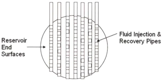
Unlike the well option, where micro-scale fractures provide the permeability, the mining option involves the creation of an underground rubble zone with macroscopic fractures. Conventional mining operations would use mine tunnels at two levels, with the levels separated by 50 to 500 meters. The top level must be below the depth where the hydrostatic pressure of the groundwater exceeds the pressure necessary to maintain the hottest water as a liquid or steam at required pressures. At the lower level, silos would be created (few meters and larger in diameter) upward from the bottom level. The silos would be spaced to prevent rock collapse. Holes for explosives would be drilled between the upper level and the top of the silos. Controlled timed explosives would then create rubble chimneys between the upper and lower level. The mined volume of the original silos is the void space in the final chimneys of broken rock between the two levels. These chimneys would then be the primary heat storage volumes. The rock in the side walls would be secondary heat storage. The tunnels at the top, the bottom, and connecting the two levels are the collector paths for hot and cold water in the heat storage reservoir and thus are sized to meet both mining requirements and nuclear geothermal operational requirements. The alternative to silos would be long linear structures. Structural engineering would determine the minimum supporting rock structure. The
Fig.2-11 Concept of Block Caving [14]
The construction technology is a combination of traditional block caving mining and the underground civil engineering done for facilities such as the Swedish SFR waste disposal facility, geological repository facilities, and the US strategic oil reserves. The distinction between traditional mining operations and underground civil engineering is that the underground civil engineering structures are designed for century lifetimes whereas mines are designed only to last as long as it takes to remove the ore. The access would include a shaft and likely an inclined tunnel to enable high volume rock removal (Swedish granite mining method).
From the viewpoint of the fluid dynamics, the mining option artificially creates flow paths with extremely low hydraulic resistance compared to those inside the rocks. Such an uneven hydraulic resistance between the artificially made paths and the naturally existing paths inside the rock forces the fluid flow towards the low resistance path. Such a phenomenon bears an important implication not only on the pressure drop but also on the heat transfer. Most of the fluid flows through the macroscopic inter-rock conduit and heat transfer no longer occurs at the pore surface of the rock, but rather occurs at the lateral surface of the fractured rocks. Such a reduction in heat transfer area leads to a delay in the heat storing process.

![Fig. 1-2 Capabilities of Energy Storage Technologies (adapted from ref [4])5](https://thumb-eu.123doks.com/thumbv2/123doknet/14449279.518332/19.918.89.802.195.636/fig-capabilities-energy-storage-technologies-adapted-ref.webp)


![Table 2-3 Summary of Energy Conversion Systems Usable with Enhanced Geothermal System [6]](https://thumb-eu.123doks.com/thumbv2/123doknet/14449279.518332/34.918.141.740.158.478/table-summary-energy-conversion-systems-usable-enhanced-geothermal.webp)