HAL Id: hal-02159214
https://hal.archives-ouvertes.fr/hal-02159214
Submitted on 18 Jun 2019
HAL is a multi-disciplinary open access
archive for the deposit and dissemination of
sci-entific research documents, whether they are
pub-lished or not. The documents may come from
teaching and research institutions in France or
abroad, or from public or private research centers.
L’archive ouverte pluridisciplinaire HAL, est
destinée au dépôt et à la diffusion de documents
scientifiques de niveau recherche, publiés ou non,
émanant des établissements d’enseignement et de
recherche français ou étrangers, des laboratoires
publics ou privés.
Low Phase Noise Digital Division by 2 and by 3 of a 30
GHz Coupled Optoelectronic Oscillator
Arnaud Collet, Olivier Llopis, Gilles Cibiel, Éric Tournier
To cite this version:
Arnaud Collet, Olivier Llopis, Gilles Cibiel, Éric Tournier. Low Phase Noise Digital Division by 2
and by 3 of a 30 GHz Coupled Optoelectronic Oscillator. European Microwave Integrated Circuits
Conference (EuMIC) 2019, Sep 2019, Paris, France. �hal-02159214�
Low Phase Noise Digital Division by 2 and by 3 of
a 30 GHz Coupled Optoelectronic Oscillator
Arnaud Collet
#1, Olivier Llopis
#2, Gilles Cibiel
*3, ´
Eric Tournier
#4 #LAAS-CNRS, Universit´e de Toulouse, CNRS, UPS, Toulouse, France*CNES, 18 Avenue Edouard Belin, Toulouse, France
{1arnaud.collet, 2olivier.llopis,4eric.tournier}@laas.fr,3Gilles.Cibiel@cnes.fr
Abstract — A frequency synthesis technique based on the division of a coupled optoelectronic oscillator (COEO) reference is presented. This technique overcomes one of the main issues of the most common frequency synthesis technique, namely the phase locked loop (PLL) : the inherent phase noise degradation of frequency multiplication. In order to keep the benefits of the frequency division technique, residual phase noise of the dividers has to be reduced as much as possible. This article discusses the results of two digital dividers, a divider by 2 and a divider by 3, both with a 30 GHz COEO reference.
Keywords — BiCMOS integrated circuits, frequency digital dividers, divide-by-three, phase noise.
I. INTRODUCTION
High frequency signals with high spectral purity are of utmost importance in a wide variety of applications such as radar, space or broadband telecommunications [1].
Due to the congestion of frequency bands below 3 GHz and the growing need in broadband systems speed, higher frequency bands are considered [2], with for instance discussions about a 28 GHz frequency band for 5G in the USA.
Currently, PLL is one of the most widespread frequency synthesis technique. It is based on the multiplication of low frequency references, generally quartz oscillators delivering frequencies from a dozen to a few hundred megahertz. Higher working frequencies mean higher multiplication factors. However, multiplying the frequency of a signal by a factor N increases its theoretical phase noise by 20 log N , in addition to the multiplier self-noise. For this reason, PLL is a questionable candidate to synthesize low phase noise high frequency signals. On the contrary, dividing the frequency of a signal by M will lower its theoretical phase noise by 20 log M , plus the divider residual phase noise.
Therefore, a frequency synthesis technique based on division of high frequency low phase noise reference is studied to confirm its viability from a phase noise performance standpoint. Contrary to PLL, target frequencies are synthesized from a high frequency reference. COEO are frequency references able to generate signals with high spectral purity up to a dozen gigahertz, making them ideal candidates for this purpose. They offer a good compromise between size, complexity and phase noise performance compared to other references at these frequencies. We have a 30 GHz COEO at our disposal [3].
The purpose of this work is to design low residual noise dividers to generate other frequencies from this reference without significantly deteriorate the COEO phase noise performance. We chose to study performances of digital dividers because of their higher flexibility over analog ones. The digital dividers we designed have fixed division ratios of 2 and 3, and are synchronous : every D Flip-Flop (DFF) composing them have the same clock. They are designed in Emitter-Coupled Logic (ECL) using a 130 nm SiGe BiCMOS technology.
This article presents the simulations and measurements results when dividing a 30 GHz COEO.
II. DIVIDERSTOPOLOGIES
A. Digital Divider by 2
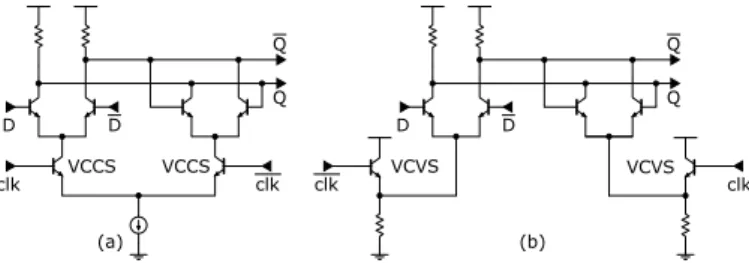
The designed divider by 2 is a DFF with the inverted output connected back to the input. A specific topology [4] is used for the latches, where the Voltage Controlled Current Sources (VCCS) of a usual D latch are replaced by Voltage Controlled Voltage Sources (VCVS). D clk D clk Q Q D clk D clk Q Q (a) (b) VCVS VCCS VCCS VCVS
Fig. 1. (a) Usual D latch (b) Low phase noise D latch
In this case, the usual D latch current source is realized with a current mirror using MOS transistors. During the simulations, we ranked the components of the circuit according to their noise contribution and we noticed that the main noise contributors were the MOS transistors used as current sources in the D latches. For this reason, we used an alternative D latch topology that uses VCVS. The VCVS are emitter followers that drive the emitters of the transistors of the differential pairs of the D latches. We keep a latch mechanism but the clk signal is inverted compared to an usual D latch. By maximizing the size of the bipolar transistor and minimizing the resistance of the emitter followers, we can obtain a substantial improvement of the phase noise compared to an usual D latch.
This divider was validated for an input frequency of 3.5 GHz [4], so the purpose is to demonstrate its functionality at much higher frequency, in this case up to 30 GHz. An optimization is done on the size of transistors, in order to lower the divider’s residual noise as much as possible while ensuring a working frequency higher than 30 GHz. One of the most valuable advantage of digital dividers compared to analog dividers is their wide bandwidth. This divider is functional from 1 GHz to 40 GHz. The minimal input power threshold to trigger the divider is −26 dBm and the maximal tested input power is 2 dBm. As it is a digital divider, the output power of −8 dBm is steady and quasi-independent from the input power. The output signal is a square signal with a 50% duty cycle. The total divider current consumption is 56 mA with a supply voltage of 3.3 V. Excluding the pads used to measure the divider, its dimensions are 158 µm × 255 µm. On figure 2, dummies recover the circuit so we add a representation of the layout on the microphotograph of the chip to illustrate underneath levels.
Fig. 2. Layout representation on a microphotograph of the divider by 2
B. Digital Divider by 3
The topology of our digital divider by 3 is common and is composed of two DFF and a NOR gate in the configuration shown in figure 3. The input DFF of the divider we designed
D clk Q DFF D clk Q DFF fin fin 3
Fig. 3. Block diagram of the digital divider-by-3
is an usual DFF and the output DFF is the same one used in
the divider by 2 described above. As a synchronous divider, the output logic gate is the one that mostly impact the overall phase noise of the divider [5]. For this reason, we use the DFF with the best phase noise performance as the output gate of the divider while keeping an usual DFF as the input gate. This divider is functional up to 32 GHz. The minimal power to trigger the divider is −12 dBm and the maximal tested input power is 2 dBm. The output power is −12 dBm. The output signal is a square signal with a 33% duty cycle. The current consumption is 60 mA with a supply voltage of 3.3 V. Excluding the pads, its dimensions are 241 µm × 257 µm. On figure 4, we add a representation of the layout on the microphotograph of the chip to illustrate.
Fig. 4. Layout representation on a microphotograph of the divider by 3
III. SIMULATION ANDMEASUREMENTRESULTS
Measurements are conducted using the 30 GHz COEO reference frequency divided by the designed dividers using a probe station. The resulting signal phase noise is measured with an Agilent Technologies E5052B Signal Source Analyzer. Both of the dividers have an input active balun to generate differential signals from the single-ended signal delivered by the COEO. Output buffers allow to deliver output current to the 50 Ω input of measurement systems. The current consumption and the phase noise deterioration of these elements are included in the following measurements.
A. Digital Divider by 2
On figure 5, the phase noise of the COEO divided by the designed divider by 2 is compared to the phase noise of the COEO ideally divided by 2 (phase noise of the COEO at 30 GHz minus 20 × log(2) = 6 dB). This is the best phase noise achievable because this is the phase noise of the frequency reference translated to the output frequency.
-160 -140 -120 -100 -80 -60 -40
1,00E+01 1,00E+02 1,00E+03 1,00E+04 1,00E+05 1,00E+06 1,00E+07
ℒ (f ) (dB c/H z) Rela�ve frequency (Hz) COEO 30GHz - 20 x log(2) COEO 30GHz divided by 2
Simulated divider phase noise (VCVS) Simulated divider phase noise (VCCS)
Fig. 5. COEO divided by 2 phase noise : Noise floor vs measured vs simulated
-160 -140 -120 -100 -80 -60 -40
1,00E+01 1,00E+02 1,00E+03 1,00E+04 1,00E+05 1,00E+06 1,00E+07
ℒ (f ) (dB c/H z) Rela�ve frequency (Hz) COEO 30 GHz - 20 x log(3) Simulated divider by 3 phase noise COEO divided by 3 measurement
Fig. 6. COEO divided by 3 phase noise : Noise floor vs measured vs simulated
We can observe that the phase noise of the COEO divided by the designed divider by 2 is almost the same that the ideally divided COEO, so the residual phase of the divider is low enough not to deteriorate the phase noise of the divided reference. On this figure, we also compare the residual phase noise of an usual divider by 2 based on a DFF with VCCS and of the optimized divider by 2 based on a DFF using VCVS. We observe an improvement of at least 6 dB with the VCVS version. Measurements results are surprisingly better than expected from the simulation. The phase noise measured is the noise of the COEO translated to 15 GHz, so the divider noise contribution is negligible in this case.
B. Digital Divider by 3
In figure 6, the phase noise of the 30 GHz COEO divided by 3 is compared to the COEO noise translated to 10 GHz and with the simulated residual phase noise of this divider at a 10 GHz output. Near the carrier, up to a 500 Hz relative frequency, the divider noise is negligible compared to the noise of the COEO. For relative frequencies from 500 Hz to 100 kHz, the phase noise is in accordance with the divider’s phase noise level expected from the simulation. At upper relative frequencies, measured phase noise is higher than expected from the simulation. We demonstrate that we are able to realize a digital divider by 3 working at 30 GHz with an acceptable level of phase noise but that phase noise is not low enough to fully preserve the performance of the COEO, so a new design of the divider will be done in order to improve it.
IV. DISCUSSION
In figure 7, measured phase noise performances of the COEO divided by 2 are compared to the phase noise
performances of three of the best frequency references [6], [7], [8] in the industry to our knowledge. We also compare the phase noise performance of the divider with a recent low noise PLL [9] that generates a frequency near the ones we are working on. However, we must keep in mind that the PLL offers some functionalities our dividers do not for the present moment, such as programmable ratios, fractional ratios and so on. All these frequency references phase noise are ideally translated to 15 GHz to be comparable with the divided by 2 COEO. -160 -140 -120 -100 -80 -60 -40
1,00E+01 1,00E+02 1,00E+03 1,00E+04 1,00E+05 1,00E+06 1,00E+07 COEO 30GHz divided by 2 RAKON 1.28GHz x 11.7 Crystek 1GHz x 15 NEL 1GHz x 15 PLL 10.6GHz x 1.415 ℒ (f ) (dB c/H z) Rela�ve frequency (Hz)
Fig. 7. COEO divided by 2 phase noise vs frequency references
We can see that the frequency reference we designed is competitive with high performances frequency references within the relative frequency range studied. From a phase noise perspective, the benefit is even more remarkable when we compare it to a frequency reference based on a PLL but as mentioned earlier, functionalities are not the same.
In figure 8, we now compare the same frequency references translated to 10 GHz with the COEO divided by 3.
-160 -140 -120 -100 -80 -60
1,00E+01 1,00E+02 1,00E+03 1,00E+04 1,00E+05 1,00E+06 1,00E+07 COEO 30GHz divided by 3 RAKON 1.28GHz x 7.8125 Crystek 1GHz x 10 NEL 1GHz x 10 PLL 10GHz ℒ (f ) (dB c/H z) Rela�ve frequency (Hz)
Fig. 8. COEO divided by 3 phase noise vs frequency references
Comparatively, we can observe that the divider by 3 is less competitive than the divider by 2 and thus the signal generated by dividing the COEO with the divider by 3 is less competitive with the other frequency references. However, we have a better phase noise than the signal generated with the PLL on most of the frequency span observed.
In order to compare these dividers with others digital dividers, we use the following figure of merit (FoM) [10]:
FoM = Lfloor− 20 log(f0) + 10 log(PDC) + 30. (1)
This FoM includes the main characteristics of digital dividers that are the noise floor Lfloor, the input frequency f0
and the power consumption PDC.
In Table 1, the divider by 2 is compared with the HMC862A programmable SiGe BiCMOS divider by 1, 2, 4 and 8 from Analog Devices operating up to 24 GHz [11]. Its characteristics are given for the configuration division by 2.
Table 1. HMC862A vs divider by 2
References Lfloor PDC f0 FoM
HMC862A −153 dBc/Hz 365 mW 24 GHz −335 dBc/Hz Div. by 2 −145 dBc/Hz 185 mW 40 GHz −334 dBc/Hz
In Table 2, the divider by 3 is compared with the HMC437 AsGa MMIC divider by 3 from Analog Devices, operating up to 7 GHz[12].
Table 2. HMC437 vs divider by 3
References Lfloor PDC f0 FoM
HMC437 −153 dBc/Hz 345 mW 7 GHz −324 dBc/Hz Div. by 3 −128 dBc/Hz 198 mW 32 GHz −315 dBc/Hz
As expected, the designed divider by 2 has competitive performances compared to one of the best digital divider to our knowledge. The designed divider by 3 performances are less competitive the Analog Devices one but it is important to note that, as SiGe digital dividers by 3 seem to be rare in the literature, we had to compare it with a divider in AsGa technology .
V. CONCLUSION
This paper presents the results of frequency synthesis by division based on a 30 GHz COEO reference divided by ECL digital dividers. A 15 GHz signal is synthesized using a divider by 2 and a 10 GHz signal using a divider by 3. In term of phase noise performance, the division of an high frequency reference is a promising alternative to frequency multiplication in PLL. Indeed, the capacity to design low residual phase noise dividers combined to the development of low phase noise high frequency reference such as COEO promise an interesting future for this synthesis technique. In this paper, ECL digital dividers are proposed. We demonstrate that we were able to design a digital divider by 2 operating at 30 GHz whose phase noise is negligible compared to the transposed noise of our reference frequency. We also demonstrate that we can design a digital divider by 3 operating at 30 GHz whose phase noise is acceptable but still need some improvements. For future prospects, we are investigating some other functionalities for digital dividers, such as the implementation of higher ratios, of programmable ratios or of fractional ratios.
ACKNOWLEDGMENT
We thank the DGA for supporting this work through ANR Astrid DIFOOL project.
REFERENCES
[1] Rohde and Schwarz, “The world between 3 GHz and 300 GHz: services and applications.” [Online]. Available: https://scdn.rohde-schwarz.com/ ur/pws/dl downloads/dl common library/dl news from rs/199/N199 70-75 services-and-applications-3GHz-300GHz f.pdf
[2] F. Khan and Z. Pi, “mmWave mobile broadband (MMB): Unleashing the 3ghz;300ghz spectrum,” in 34th IEEE Sarnoff Symposium. IEEE, pp. 1–6. [Online]. Available: http://ieeexplore.ieee.org/document/5876482/ [3] A. Ly, V. Auroux, R. Khayatzadeh, N. Gutierrez, A. Fernandez, and
O. Llopis, “Highly spectrally pure 90-GHz signal synthesis using a coupled optoelectronic oscillator,” vol. 30, no. 14, pp. 1313–1316. [Online]. Available: https://ieeexplore.ieee.org/document/8376022/ [4] S. Godet, ´E. Tournier, O. Llopis, A. Cathelin, and J. Juyon, “A low phase
noise and wide-bandwidth BiCMOS SiGe:c 0.25 µm digital frequency divider for an on-chip phase-noise measurement circuit,” in IEEE SiRF 2009, pp. 1–4.
[5] M. Apostolidou, P. G. Baltus, and C. S. Vaucher, “Phase noise in frequency divider circuits,” in 2008 IEEE International Symposium on Circuits and Systems. IEEE, pp. 2538–2541. [Online]. Available: http://ieeexplore.ieee.org/document/4541973/
[6] RAKON, “LNO 1280 b1 (datasheet),” 00000. [Online]. Available: http://www.rakon.com/products/families/download/file?fid=39.258 [7] Crystek Corporation, “CCSO-914x3-1000 ultra-low phase noise 1ghz
SAW clock CCSO-914x3-1000 (datasheet),” 00000. [Online]. Available: http://www.mouser.com/ds/2/94/CCSO-914X3-1000-180198.pdf [8] N. F. Controls, “Low phase noise 1 GHz OCXO in 36x27 mm
“europack” (datasheet).”
[9] C. Li, H. Lu, X. Zhang, and N. Yuan, “Design of x-band low phase noise and low spurious frequency source based on HMC778,” in 2017 IEEE 2nd Advanced Information Technology, Electronic and Automation Control Conference (IAEAC). IEEE, pp. 438–442. [Online]. Available: http://ieeexplore.ieee.org/document/8054052/
[10] S. Horst, S. Phillips, H. Lavasani, F. Ayazi, and J. D. Cressler, “SiGe digital frequency dividers with reduced residual phase noise,” in 2009 IEEE Custom Integrated Circuits Conference. IEEE, pp. 251–254. [Online]. Available: http://ieeexplore.ieee.org/document/5280851/ [11] Analog Devices, “HMC862a 0.1 GHz to 24 GHz, low noise,
programmable divider.” [Online]. Available: https://www.analog.com/ media/en/technical-documentation/data-sheets/hmc862a.pdf
[12] ——, “HMC437ms8g SMT GaAs HBT MMIC DIVIDE-BY-3, DC - 7 GHz.” [Online]. Available: https://www.analog.com/media/en/ technical-documentation/data-sheets/hmc437.pdf