An Asynchronous Distributed Access Control Architecture
for IP over ATM Networks
** This work is funded by DRET.
Olivier PAUL
Maryline LAURENT
Sylvain GOMBAULT
ENST de Bretagne, RSM Department
2 rue de la châtaigneraie - BP 78 35512 CESSON Cedex - France
Email : {Olivier.Paul|Maryline.Laurent|Sylvain.Gombault}@enst-bretagne.fr
Abstract
In this article, we describe a new architecture providing the access control service in both ATM and IP-over-ATM networks. This architecture is based on agents distributed in network equipment. It is well known that distribution makes the management process more difficult. This issue is raised and we provide an algorithm to distribute the access control policy on our agents. The comparison with other approaches shows that this architecture provides big improvements in ATM-level access control, scalability and QoS preservation.
Keywords: Access Control, Management, Security, ATM, Agents, IP-over-ATM.
1. Introduction
In the recent past, much attention has been paid developing security services for ATM networks. This resulted in the creation of many working groups within (and outside) the standardization bodies. One of them is the security Working Group of the ATM Forum created in 1995, which released its version 1.0 specifications in February 1999. Confidentiality, authentication, integrity and some kind of access-control have been considered. Access control as defined by the ISO in [1] is a security service used to protect resources against unauthorized use. The ATM technology has been specified to transport various kinds of flows and allows users to specify the QoS (Quality of Service) applying to these flows. Communications are connection oriented and a signalling protocol is used to set up, control and release connections. In this article we show that the classical approach supplying the access control service (commonly called firewall) is unable to preserve the QoS. We then describe a new access control architecture for ATM and IP-over-ATM networks which does not alter the negotiated QoS.
The next section analyses current solutions providing the access control service in the ATM and IP over ATM networks. Section 3 describes the way to provide the
access control service through an asynchronous distributed architecture. As a conclusion we make a comparison between our solution and other proposed approaches and we show that our architecture is a good alternative to current solutions.
2. Proposed solutions
Several solutions have been proposed in order to provide some kind of access-control in ATM and IP over ATM networks. This section is divided into three parts. In the first part we consider the adaptation of the Internet «classical» firewall architecture to ATM networks. In the second part we describe the solution proposed by the ATM Forum. In the third part we describe various solutions proposed to improve the «classical» firewall solution. As a conclusion we make a comparison between all these solutions.
2.1. Classical solution
The first solution [12] is to use a classical firewall located between the internal and public networks in order to provide access-control at the packet, circuit and application levels. As such the ATM network is considered as a level 2 layer offering point to point connections. As a result access-control at the ATM level is not possible and end to end QoS is no longer guaranteed.
At the IP and circuit levels, IP packets are reassembled from the ATM cells. Access-control is supplied using the information embedded in the TCP, UDP and IP headers. Packets are filtered by comparing the fields in the headers such as the source and destination addresses, the source and destination ports, the direction and the TCP flags with a pattern of prohibited and allowed packets. Prohibited packets are destroyed whereas allowed packets are forwarded from one interface to the other. When the same QoS is negotiated on both sides of the firewall, the end to end QoS may be modified in the following ways:
• Reassembly, routing, filtering and deassembly operations increase the Cell Transit Delay.
• Internal operations done over IP packets may increase the Cell Loss Ratio.
• The time spent to reassemble and disassemble the packets is proportional to the packet sizes, which are variable. As a result, the Cell Transit Delay Variation may be different from the CTDV value negotiated on each side of the firewall.
• Routing and filtering actions operate at the software level. Thus the load of the system may cause variations in the Sustainable and Minimum Cell Rate. Application procedures are then filtered at the application level by proxy applications in accordance with the security policy. Like with the IP or circuit level filters, the QoS is affected, but much more strongly, since the traffic has to reach the application level. Moreover since the filtering operations are provided in a multitasking environment, desynchronization between the flows can occur.
This kind of solution is reported to have performance problems in a high speed network environment ([4], [6]). The latest tests ([7]) show that this access control solution is unsuccessful at the OC-3 (155 Mb/s) speed.
2.2. The access control service as considered by
the ATM Forum
The access-control service as defined in the ATM Forum security specifications ([13]) is based on the access- control service provided in the A and B orange book classified systems. In this approach one sensitivity level per object and one authorization level per subject are defined. These levels include a hierarchical level (e.g. public, secret, top secret, etc.) and a set of domains modelling the domains associated with the information (e.g. management, research, education, etc.). A subject may access an object if the level of the subject is greater than the level of the object and one of the domains associated with the subject includes one of the domains associated with the object.
In the ATM Forum specifications, the sensitivity and authorization levels are coded according to the NIST [5] specification as a label, which is associated with the data being transmitted. This label may be sent embedded into the signalling, or as user data prior to any user data exchanges. The access-control is operated by the network equipment which verifies that the sensitivity level of the data complies with the authorization level assigned to the links and interfaces over which the data are transmitted.
The main advantage of this solution is its scalability since the access control decision is made at the connection setup and does not interfere with the user data. However it suffers from the following drawbacks:
• The network equipment is assumed to manage sensitivity and authorization levels. This is not provided in current network equipment.
• A connection should be set up for each sensitivity level.
• The access-control service as considered in traditional firewalls (i.e. access-control to hosts, services) is voluntarily left outside the scope of the specification.
2.3 Specific solutions
The above limitations have been identified and many proposals have been made in order to supply the «traditional» access-control service in ATM networks. These solutions may be classified into two classes: industrial and academic solutions.
Industrial solutions
The first industrial solution (Cisco, Fore) uses a classical ATM switch that is modified to filter ATM connection set up requests based on the source and destination addresses. The problem with this approach is that the access- control is not powerful since the parameters are very limited.
The second one (Storagetek) is also based on an ATM switch. However this switch has been modified to supply access-control at the IP level. Instead of reassembling cells for packet headers examination like in traditional firewalls, this approach is expected to find IP and TCP/UDP information directly in the first ATM cell being transmitted over the connection. This approach prevents delays being introduced during cell switching. Storagetek has also developed a specific memory called CAM (Content Addressable Memory) designed to speed up the research in the access-control policy. This approach is the first one taking into account the limitations introduced by the classical firewall approach. However some problems have not yet been solved:
• Access-control is limited to the network and transport levels. ATM and application levels are not considered.
• IP packets including options are not filtered since options may shift the UDP/TCP information in the second cell. This causes a serious security flaw.
• The device is not easy to manage especially when dynamic connections are required, since connection filters have to be configured manually.
• Performances of the device are not very scalable. An OC-12 (622 Mb/s) version of this product was announced in 1996 but has not been yet exhibited.
Academic solutions
Both academic solutions being proposed are based on the above Storagetek architecture, but they introduce some improvements to cope with Storagetek problems.
The first approach [3] uses an FPGA specialized circuit associated with a modified switch architecture. At the ATM level, the access control at connection establishment time is improved by providing filtering capabilities based on the source and destination addresses. This approach also allows ATM level PNNI (Private Network to Network Interface) routing information to be filtered. At the IP and circuit levels the access-control service is similar to the one provided by the Storagetek product.
• This solution is interesting since it is the most complete solution being currently implemented. However it suffers from many limitations:
• Special IP packets (e.g. packets with optional fields in the header) are not processed.
• Only a small part of the information supplied by the signalling (i.e. source and destination addresses) is used.
• Access-control at the application level is not considered.
The second approach [16] is the most complete architecture being currently proposed. This solution provides many improvements in comparison with the Storagetek architecture. The most interesting idea is the classification of the traffic. The traffic is classified into four classes depending on the ATM connection QoS descriptors and on the processing allowed to be done over it. Class A provides a basic ATM access-control. ATM connections are filtered according to the information provided by the signalling (i.e. source and destination addresses). Class B provides traffic monitoring. The analysis of the traffic is made on a copy of the flow. When a packet is prohibited, the reply to this packet is blocked. Class C is associated with packet filtering. IP and transport packet headers are reassembled from the ATM cells and analysed. During this analysis the last cell belonging to the packet called LCH (Last Cell Hostage) is kept in memory by the switch. The analysis should be at least faster than the time spent by the whole packet crossing the switch. When the packet is allowed, the LCH is released, but when the packet is prohibited the LCH is modified so that a CRC error occurs and the packet is rejected. For class D, the access control processing is similar to that of the firewall proxy.
This classification expects the switch to separate traffic with QoS requirements from traffic without QoS requirements. As such the traffic with QoS requirements is allowed to cross the switch without being delayed. Table 1 gives the filtering operations depending on the
level implementing the access control and the traffic QoS requirements.
Table 1. Use of the access control classes
Level/Application With QoS requirements
Without QoS requirements
Application No Access control Class D Transport Class B Class C
ATM Class A Class A
This approach is very interesting since it introduces many improvements (traffic classification, LCH) over all the other proposals. However some problems remain:
• Few parameters are used to supply the access control service at the ATM level.
• Access control is not provided at the application level for applications requiring QoS.
• Traffic monitoring only applies to connection oriented communications, and UDP packets cannot be filtered using this technique.
• This architecture is complex so that it is likely that scalability is not offered
• No implementation has been exhibited.
The problems most often met are the lack of scalability and the impact on QoS introduced by the access control service. As a consequence, it appears of interest to develop a scalable architecture that could provide the access control service while maintaining the negotiated QoS.
3. An agent based access control architecture
3.1. Introduction
The goal of our architecture is to provide a scalable access-control service without altering the QoS negotiated for a connection. We selected a distributed architecture approach in order to have more scalability than in a centralized approach. As stated in [14] a distributed architecture induces many advantages. These advantages are as follows:
• Better fault tolerance. If a device providing the access control service fails, this device is the only one affected. Other devices are able to continue to communicate.
• Security level improvement. For an intruder to control the whole network, it is necessary to subvert all the access control devices one after the other.
• Protection against internal attacks. Internal attacks against internal devices can be avoided and detected since all the devices are protected.
• Realistic information about the flows. [11] shows that firewalls and intrusion detection tools systems rely
upon a mechanism of data collection which is fundamentally flawed. These systems watch all the traffic on the network, and scrutinize it for patterns of suspicious activity. However there is not enough information on the wire on which to base conclusions about what is actually happening on networked machines. Two classes of attacks (traffic insertion and evasion) which exploit this fundamental problem are exhibited thus showing that centralized traffic analysis systems cannot be fully trusted.
• A distributed architecture is not prone to these attacks since all the necessary information about the connections can be found on the end devices themselves.
• Performance improvement. For centralized devices to filter traffic, it is necessary to reassemble frames and packets in order to isolate flows that require filtering. Therefore, overhead is introduced by the controller. On the other hand, in a distributed architecture, the traffic is naturally reassembled. As a consequence, the access control processing introduces much less overhead than in the centralized approach.
• Scalability improvement. The access control processing can be distributed over several devices. As a result, very high rates can be supported, without needing a powerful centralized device.
• Efficiency improvement. As mentioned in section 1 many protocol stacks can be used above the ATM model. Providing access control mechanisms for all these protocols on a single device is not very efficient. In a distributed architecture, access control mechanisms and access control policy can be specific to the protocol stack being used. This results in less complex and thus more efficient equipment.
A distributed framework has also some disadvantages. It is more difficult to manage. Detecting attacks against several devices requires each device to cooperate with one another, which is not an easy task. The main disadvantage is that every device on the network has to be modified in order to supply the access control service. Another problem with a distributed architecture is the mean to exchange access control information.
In section 3.2 we show how a management agent can be modified in order to supply the access control service. Section 3.3 gives some indication to solve the problem of managing the distributed architecture. Finally section 3.4 describes a method to efficiently distribute the access control policy on our access control agents.
3.2. Access control enforcement
It is well known that communication devices keep information about ongoing communications in their protocol stack. Some of this information has been
standardized for management purpose [15]. The access to these data is performed through a piece of software called management agent. We demonstrated in [9] that most of the relevant information from an access control point of view can be accessed through this kind of agent.
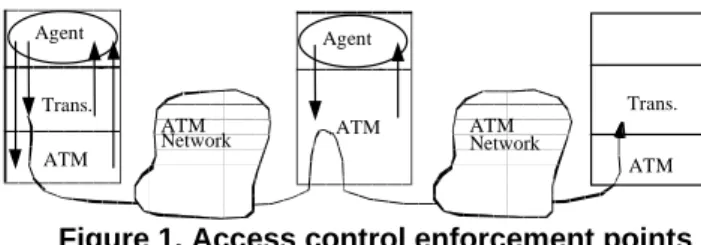
Our architecture is based on a modified management agent. This agent can be located on a terminal device or on an intermediate device as illustrated in figure 1.
ATM ATM
Trans. Trans.
ATM Agent
ATM
Network ATMNetwork
Agent
Figure 1. Access control enforcement points
The agent has to be modified in order to introduce the access control operations. It periodically polls objects located in the protocol stack describing communications. It then compares the values of these objects with the allowed values. The allowed values describe part of the access control policy to be applied in that agent. Thus the allowed values may vary from one agent to another. When prohibited values are detected, the agent interacts with the protocol stack in order to stop the prohibited action. A more detailed description of the agent architecture can be found in section 3.4. Our architecture has the following advantages:
• The information used to provide the access control service is examined asynchronously by the agent at the application level. Thus no impact on the QoS can be induced.
• The modifications of the system providing the access control service are small. Only our access control agent has to be added.
However, selecting the polling rate may not be easy. Indeed a too short interval of polling introduces unuseful overhead for the system whereas a too long interval of polling decreases the security level provided by the agent since some events will be missed by the agent thus introducing possible security flaws.
3.3. Access control management
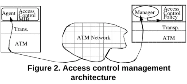
As explained in section 3.1 a distributed architecture is quite difficult to manage. To solve this management pro-blem, the three elements depicted in figure 2 are defined:
• The Access Control management application is responsible for configuring each agent with the relevant access control rules. It should also retrieve access control results from the agents and should analyse them to detect distributed attacks.
• The access control MIB is located on the access control agent device and is remotely managed by the
manager through the agent. This MIB includes both access control rules, and results from the access control process.
• The management protocol used to carry information between the access control manager and the access control agent has to supply integrity, authentication, access control and confidentiality services. The SNMPv2 [15] and SNMPv3 [2] protocols seem to be good candidates since they supply all these services.
Agent ATM Network ATM Manager ATM Transp. Trans. Access Control Policy Access Control MIB
Figure 2. Access control management architecture
3.4. Access control policy distribution
One of the biggest problems in managing our access control architecture is to decide how to distribute the access control policy on our access control agents. The first step in solving this problem is to find a way to express the access control policy.
Expressing the access control policy
In order to express the access control policy we define an Access Control Policy Description Language (ACPDL). This language is based on the Policy Description Language [8] currently being defined by the Policy working group at the IETF. In our language an access control policy is described by a set of rules. Each rule is made up of: a set of conditions and one action which has to be executed if the conditions are met. The following BNF (Backus-Naur Formalism) expression describes the rule syntax.
Rule ::= IF <Conditions> THEN <Action>
All the conditions have the same generic structure (BNF notation):
Condition ::= <ACCESS CONTROL PARAMETER> <RELATIONAL OPERATOR> <VALUE>
Depending on the level in the protocol stack, various access control parameters may be used:
• At the ATM level useful access control parameters have been described in [10], which include the traffic type, connection identifiers, addressing information, QoS descriptors and service identifiers.
• At the transport level most of the included parameters are commonly used to provide access control in firewalls (e.g. addressing information, ports, etc.).
• At the application level we define two generic parameters: the application user identifier and the application state.
• Timing parameters have also been included in order to specify when a rule should apply.
Actions also have a generic structure (BNF notation).
Action ::= <ACTION> <ACTION LEVEL>
The action can be to permit or to deny the communication. The level describes the layer (i.e. ATM, Transport, Application) where the action has to be executed.
Figure 3 provides an example of how a rule prohibiting connections between two ATM devices for the Video On Demand service can be expressed using the ACPDL. In this example both devices are identified by their ATM ad-dresses and the video service is identified by the Broadband Higher Layer Identifier (BHLI).
IF (SRC_ADDRESS =
47.007300000000000000002402.08002074E4 57.00) AND (DST_ADDRESS =
47.007300000000000000002404.0800200D6A D3.00) AND (BHLI_TYPE = 04) AND
(BHLI_ID = 00A03E00000002) THEN DENY ATM_CONNECTION ;
Figure 3. Access control rule example
Distributing the access control rules
Before describing our distribution method, we have to describe our agents' internal structure in order to explain how access control rules are executed. As shown in figure 4 an agent is made up of two main parts. The first part is dedicated to access control management whereas the second part provides the access control service. The access control part also include two parts. The first one, called Access Controller is common to each agent. Its goal is to translate the access control rules retrieved from the Access Control MIB into Access Control commands. The access controller interacts with the second part called AC library through the Access Control Interface. The goal of the AC library is to hide the implementation of the access control objects to the access controller. The AC library translates commands received through the AC interface into real system commands and sends these commands to the real system through the system interface. This translation process is described in figure 4.
Since the AC interface is the same for each system, matching access control conditions and actions to access control objects is an easy task. Depending on the role of
the network element on which it is located, each agent may provide a mapping between an Access Control Object and a System Object or not. Therefore describing which access control objects are implemented on equipment is important for the distribution process. One possible way to describe these objects could be to use the
Management Information Bases (MIBs) defined by the standardization organisations since some of these MIBs include the most useful objects from an access control point of view ([9]). Since all of our access control conditions and actions cannot be mapped on existing management objects new MIBs have to be defined.
Agent
AC library Access Controller AC Interface
Real System Real system interface
Access Control Conditions
Access Control Objects Access Control Action Access Control Rules
Access Control Command
System Objects System Command Access Management Control Process Access Control Results To the AC Management Application Access Control MIB
Figure 4. Agent’s internal structure
The goal of the distribution algorithm is to efficiently assign access control rules to our access control agents. This distribution process must follow two laws:
• A rule must not be assigned to an agent where this rule cannot be executed. A rule cannot be executed when an access control object required by the rule cannot be mapped to a real system object by the AC library (1).
• A rule must not be assigned to an agent where this rule will never be executed. A rule will never be executed when:
- The rule is located on a terminal device and the rule does not apply to this device (2).
- The rule is located on an intermediate device D but does not apply to D and does not apply to a device interconnected by D (3).
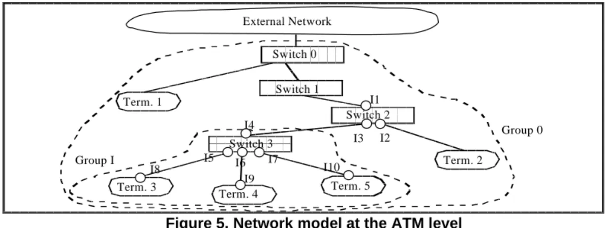
To follow these laws the distribution process has to use a description of the network which has to be protected. Since we want to provide the access control service at the ATM, MAC, IP and application levels, the network is sliced into three layers (i.e. ATM, MAC, IP). Each slice is modelled by a tree describing interconnections between network devices at a single level.
External Network Switch 0 Switch 1 Switch 2 Term. 3 Term. 5 Group I Group 0 Switch 3 Term. 1 Term. 4 Term. 2 I1 I2 I3 I4 I5 I6 I7 I8 I9 I10
Figure 5. Network model at the ATM level
As shown in figure 5, two kinds of elements can be described. There are intermediate elements which interconnect other elements (i.e. switch devices in our example) and non intermediate elements which are called terminal elements (i.e. Term. devices).
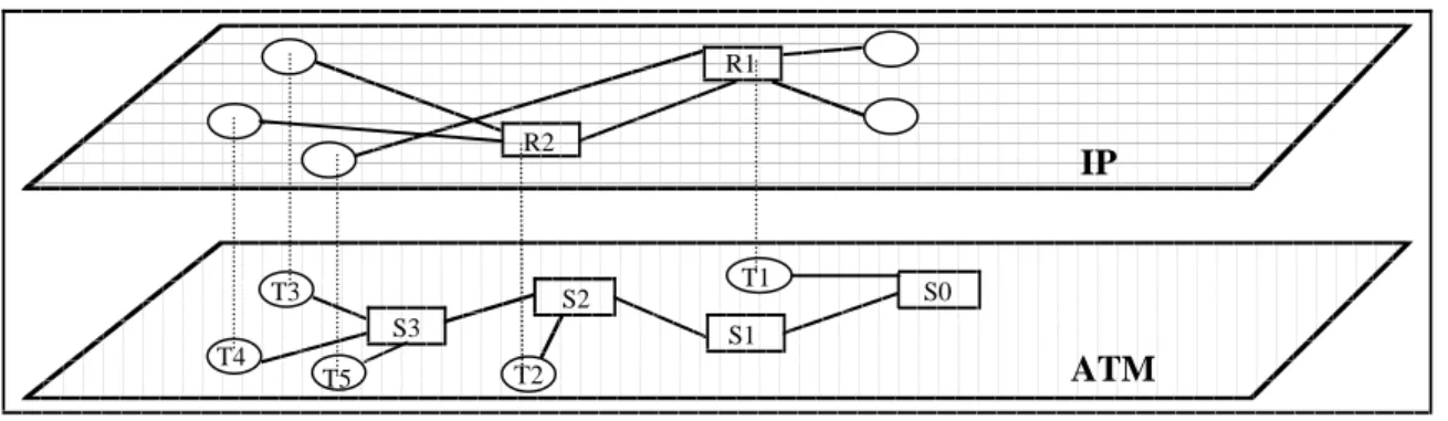
Since a terminal element at the ATM level can behave like an intermediate element at a higher layer, a distinction has to be made for each layer. Figure 6 describes possible mappings between network elements at the ATM and IP levels. Possible mappings include a one
to one mapping (i.e. one ATM element for one IP or MAC element) which is the most common case. The one to many (i.e. one ATM element for many MAC elements) case may happen in an emulated LAN environment when several LANs are configured over the same physical
network. The one to zero mapping case happens when the device only provides ATM connectivity (e.g. ATM switches). Finally, the zero to many mapping case happens when the device is interconnected to the ATM network through a non ATM link.
ATM
IP
S0 S1 S2 S3 R1 R2 T4 T3 T5 T2 T1Figure 6. Interlayer relationships
In order to describe interactions between these elements we use three classes of objects:
The Interface class describes an interconnection point between two elements. Examples of interfaces are given in figure 5 where Switch 3 has three interfaces called I1,I2 and I3. Each Interface object is associated with the corresponding level (i.e. ATM, MAC, IP), type (i.e. Intermediate, Terminal) and address. Three functions (I.level, I.type, I.address) have been associated with the Interface class to manage this information.
The Group class describes the interconnections between interface objects. Each Group object is associated with its level (i.e. ATM, MAC, IP), list of connected interfaces and master interface (i.e. the interface to leave the group). Figure 5 describes two groups called Group 0 and Group I. In this example, Group I includes six pairs of interconnected interfaces and has I4 as master interface. Three functions (G.level, G.connects, G.master) have been associated with the Group class to manage this information.
The Device class describes the interfaces belonging to a same physical device. Each Device object is associated with a set of interfaces and the access control objects implemented by the access control agent located on the device. Figure 6 shows an example of relations described by the Device class. In this example, the device associated with T2 and R2 holds four interfaces (One at the ATM level and three at the IP level). Two functions (G.maps, I.stores) have been associated with the Device class to manage this information.
Figure 7 provides the distribution algorithm. The algorithm implements the three distribution laws ((1), (2), (3)) and uses the Access Control Policy modelled by a set of rules ({rule}) and the network description modelled by
the three sets described above ({Group}, {Device}, {Interface}).
Four external functions are used:
• objects(r) provides the set of access control objects required by the access control rule r.
• interface(r) provides the set of interfaces to which the access control rule r applies.
• Associate(r,d) associates rule r with device d.
• Dissociate(r,d) dissociates rule r from device d.
For each i ∈ {Interface} do
G = {g ∈ {Group}/i ∈ g.connects}; D = {d ∈ {Device}/(i0,i1) ∈ d.maps, (i0=i|i1=i)}; M = {m ∈ {Group}/m.master = i}; N = {k ∈ {Interface}/k ∈ m.connects, m ∈ M};
For each r ∈ {Rule} do For each d ∈ D do Associate(r,d); If ∃ o ∈ objects(r)/ o ∉ d.stores then Dissociate(r,d); /* case (1) */ Else If i ∉ interface(r) then If i.type = «terminal» then Dissociate(r,d); /* case (2) */ Else
If ∃ j ∈ interface(r)/j ∉ N then
Dissociate(r,d); /* case (3) */
Optimisations
Providing more information about our security policy allows us to optimise our distribution process. Both optimisations in this section are based on the fact that the type of our access control policy is «What is not explicitly permitted is prohibited». With this kind of access control, a «Deny rule» always describes a subset of a «Permit rule». This type of access control policy is the most common but the opposite type (i.e. «What is not explicitly prohibited is allowed») would result in similar optimisations.
Our first optimisation applies to «Deny rules». The distribution of these rules must follow the following laws:
• If a «Deny rule» can be distributed over several cascading agents, the rule has to be distributed to the element closest to «terminal» devices (4).
• «Deny rules» don't have to be duplicated since a single «Deny rule» can block a communication (5). These laws provide a better efficiency since it allows a smaller subset of rules to be attached to each access control agent.
Figure 8 provides the optimisation algorithm. This algorithm implements distribution laws (4) and (5). We define two additional external functions:
• action(r) provides the type of action specified by the access control rule r.
• associated(r,d) informs whether if access control rule r has been associated with device d by the basic distribution algorithm.
For each r ∈{Rule}/action(r) = «DENY» do
For each d ∈{Device} do I = {i ∈ {Interface}/ (i0,i1)∈ d.maps,(i0=i|i1=i)}; G = {g ∈ {Group}/g.master ∈ I}; M = {m ∈ {Interface}/m ∈ g.connects, g ∈ G}; E = {e ∈ {Device}/(i0,i1) ∈ e.maps, e ≠ d, (i0 ∈ M| i1 ∈ M)}; If associated(r,d) then If ∃ e ∈ E/associated(r,e) then Dissociate(r,d); /* case (4) */ For each r ∈ {Rule}/action(r) = «DENY» do
D = { d ∈ {Device}/associated(r,d)}; Let be d ∈ D;
For each e ∈ D/e ≠ d
Dissociate(e,d); /* case (5) */
Figure 8. “Deny” based optimisations.
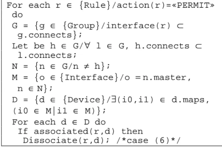
The second optimisation applies to «Permit» rules. These rules have to be duplicated between the source and
the destination of each communication that has to be controlled. The basic distribution algorithm provides this property. However when the communication to be controlled takes place between two internal devices, our basic distribution algorithm distributes these rules between the root of our network tree to the first device interconnecting our two devices. These rules are useless and have to be removed. Moreover removing these rules also provides an address spoofing protection because communications coming from the outside with external addresses will be discarded since not explicitly permitted.
• Rules describing communications between two internal devices have only to be distributed on the smaller subset of agents interconnecting these devices (6).
Figure 9 provides the optimisation algorithm. This algorithm implements distribution law (6).
For each r ∈ {Rule}/action(r)=«PERMIT» do G = {g ∈ {Group}/interface(r) ⊂ g.connects}; Let be h ∈ G/∀ l ∈ G, h.connects ⊂ l.connects; N = {n ∈ G/n ≠ h}; M = {o ∈ {Interface}/o = n.master, n ∈ N};
D = {d ∈ {Device}/∃(i0,i1) ∈ d.maps, (i0 ∈ M|i1 ∈ M)};
For each d ∈ D do
If associated(r,d) then
Dissociate(r,d); /*case (6)*/
Figure 9. “Permit” based optimisation.
Once rules have been associated to devices, the management application is able to configure the relevant agents using the management protocol.
4. Conclusion
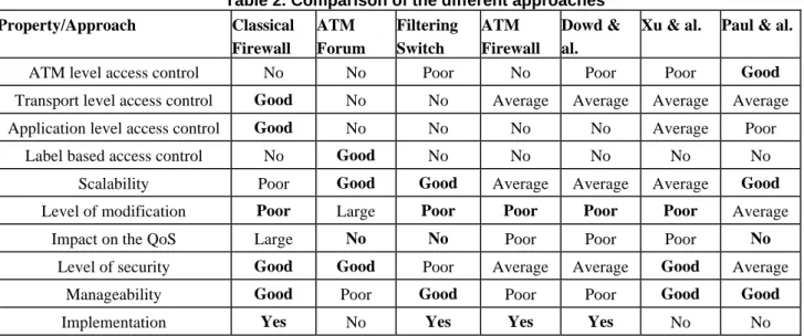
As a conclusion, table 2 compares all the competing approaches designed to provide access control on both ATM and IP over ATM networks. As we can see, our approach has the following advantages:
• Good access control at the ATM level.
• Very good scalability thanks to a distributed architecture.
• Good performance through an efficient distribution method.
• No impact on the QoS thanks to the asynchronous information retrieval process.
• Good manageability through a management and security integrated approach.
Table 2. Comparison of the different approaches Property/Approach Classical Firewall ATM Forum Filtering Switch ATM Firewall Dowd & al.
Xu & al. Paul & al.
ATM level access control No No Poor No Poor Poor Good
Transport level access control Good No No Average Average Average Average Application level access control Good No No No No Average Poor
Label based access control No Good No No No No No Scalability Poor Good Good Average Average Average Good
Level of modification Poor Large Poor Poor Poor Poor Average
Impact on the QoS Large No No Poor Poor Poor No
Level of security Good Good Poor Average Average Good Average Manageability Good Poor Good Poor Poor Good Good
Implementation Yes No Yes Yes Yes No No
This work could be usefully continued in two directions. The first direction is its implementation since this might give us interesting feedback on the real performance and security level provided by the architecture. The second direction is the extension of our architecture to other types of networks, our architecture being easily adaptable to other kinds of network that are based on a layer 2 switching and that consider QoS as an important constraint.
5. References
[1] ISO 7498-2:1989, Information processing systems -- Open Systems Interconnection -- Basic Reference Model -- Part 2: Security Architecture, ISO, 1989.
[2] Basking in Glory-SNMPv3, Dan Backman, Network Computing, August 1998.
[3] An FPGA-Based Coprocessor for ATM Firewalls, J. McHenry, P. Dowd, F. Pellegrino, T. Carrozzi, W. Cocks, in proceedings of IEEE FCCM'97, April 1997.
[4] Firewalls: Don't Get Burned, David Newman, Helen Holzbaur, and Kathleen Bishop, Data Communications, March 1997.
[5] Standard Security Label for Information Transfer, Federal Information Processing Standards Publication 188, National Institute of Standards and Technology, September 1994.
[6] ATM Net Management: Missing Pieces, Joe Abusamra, Data Communications, May 1998.
[7] Firewall Shootout Test Final Report, Keylabs, May 1998, Networld+Interop'98.
[8] Policy Framework Definition Language, draft-ietf-policy-framework-pfdl-00.txt, John Strassner, Stephen Schleimer, Internet Engineering Task Force, 17 November 1998. [9] Où trouver les informations de contrôle d'accés dans le cas
des réseaux ATM, O. Paul, M. Laurent, Technical report, ENST de Bretagne, August 1998.
[10]Manageable parameters to improve access control in ATM networks, O. Paul, M. Laurent, S. Gombault, 5th Workshop of the HP OpenView University Association HPOVUA'98, April 1998.
[11]Insertion, evasion, and denial of service: eluding network intrusion detection, T. Ptacek, T. Newsham, Technical report, Secure Network, January 1998.
[12]A network firewall, M. Ranum, Proc. World Conference on System Administration and security, 1992.
[13]ATM Security Specification Version 1.0, The ATM Forum Technical Committee. February 1999.
[14]On the modeling , design and implementation of firewall technology, Christoph Schuba, Ph.D. Thesis, Purdue University, December 1997.
[15]SNMP, SNMPv2 and CMIP, The pratical guide to network management Standards. William Stallings. Addison-Wesley. 1993.
[16]Design of a High-Performance ATM Firewall, J. Xu, M. Singhal, Technical report, The Ohio State University, 1997.