READ THESE TERMS AND CONDITIONS CAREFULLY BEFORE USING THIS WEBSITE.
https://nrc-publications.canada.ca/eng/copyright
Vous avez des questions? Nous pouvons vous aider. Pour communiquer directement avec un auteur, consultez la
première page de la revue dans laquelle son article a été publié afin de trouver ses coordonnées. Si vous n’arrivez pas à les repérer, communiquez avec nous à PublicationsArchive-ArchivesPublications@nrc-cnrc.gc.ca.
Questions? Contact the NRC Publications Archive team at
PublicationsArchive-ArchivesPublications@nrc-cnrc.gc.ca. If you wish to email the authors directly, please see the first page of the publication for their contact information.
Archives des publications du CNRC
This publication could be one of several versions: author’s original, accepted manuscript or the publisher’s version. / La version de cette publication peut être l’une des suivantes : la version prépublication de l’auteur, la version acceptée du manuscrit ou la version de l’éditeur.
Access and use of this website and the material on it are subject to the Terms and Conditions set forth at
Monitoring performance of corrosion inhibitors in a reinforced concrete bridge
Cusson, D.
https://publications-cnrc.canada.ca/fra/droits
L’accès à ce site Web et l’utilisation de son contenu sont assujettis aux conditions présentées dans le site LISEZ CES CONDITIONS ATTENTIVEMENT AVANT D’UTILISER CE SITE WEB.
NRC Publications Record / Notice d'Archives des publications de CNRC: https://nrc-publications.canada.ca/eng/view/object/?id=c1a72f67-9c33-4e5d-bd40-3fe8f0da708f https://publications-cnrc.canada.ca/fra/voir/objet/?id=c1a72f67-9c33-4e5d-bd40-3fe8f0da708f
APWA International Public Works Congress
NRCC/CPWA Seminar Series “Innovations in Urban Infrastructure” MONITORING PERFORMANCE OF CORROSION INHIBITORS
IN A REINFORCED CONCRETE BRIDGE
By D. CUSSON1
Institute for Research in Construction, National Research Council of Canada 1500 Montreal Road, Ottawa, CANADA, K1A OR6
Abstract Résumé
This paper describes an on-going consortium established two years ago to evaluate the long-term field performance of proprietary corrosion inhibiting systems for the rehabilitation of reinforced concrete bridges. The field monitoring consists of annual visits to the bridge to conduct visual inspections and corrosion surveys of the traffic-exposed face of the reconstructed bridge parapet. Further, innovative remote wireless systems using cellular phone technology are used to record vital information on the concrete parapet. The field evaluation is also supported by lab experiments which consist of tests on cores taken annually from the bridge parapet and of an accelerated corrosion lab study on field-cast reinforced concrete prisms.
Keywords: bridge instrumentation, corrosion inhibitors, field performance
1 Introduction
Bridge repair is a costly activity in North America, yet little information exists on the long-term performance of repair and protection materials. Because of this, bridge owners and designers have difficulty in selecting appropriate materials that are compatible with the substrate and suitable for the application. Climate extremes and deicing salts on bridges can damage concrete further via rebar corrosion (Seabrook and Hansson 1996; Mirza et al. 1998). As a result, the repair is short-lived.
To address this problem, the National Research Council of Canada (NRC) formed a consortium of interested groups, including owners and manufacturers. The main objective of the project is to ascertain the performance and understand factors affecting the effectiveness of corrosion inhibitors for bridge decks via monitoring their in-situ behavior over five years. The corrosion inhibiting systems include (i) concrete admixtures, (ii) rebar coatings, and/or (iii) concrete coatings/sealers.
Manufacturers will benefit from appraisals of products, product improvement feedback and input from product users. Bridge owners will gain useful product appraisals, rankings and long-term performance data.
1 Dr. Daniel Cusson is a Research Officer at the National Research Council of Canada. He is leading
field consortium projects on the rehabilitation of concrete bridges. He can be reached at
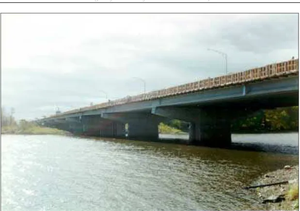
Figure 1: Vachon bridge during rehabilitation in the summer 1996
2 Test site
The structure selected is the Vachon bridge located north of Montreal (Quebec) on Highway 13 across Mille-Îles River (Figure 1). This 6-lane wide, 714-m long bridge includes twenty-one 34-m long single spans of prestressed concrete girders supporting a reinforced concrete slab. In 1996, the Ministry of Transportation of Quebec (MTQ) proceeded with the replacement of the deteriorated parapets, the patching of the concrete slab, and the replacement of its membrane and asphalt layer.
A group of 10 spans (34-m long each) of the east parapet (identified as Span 12 to 21 in Figure 2) was selected as the test site for the application of the proprietary corrosion inhibitors during the reconstruction of the east parapet in October 1996. The concrete parapet presented many advantages over the slab as the test site: it presented similar initial conditions and, as opposed to the slab with its membrane and asphalt cover, it is directly exposed to salt spray and allows direct measurements of half-cell potential and linear polarization resistance on its bare concrete surface.
The existing anchor rebars and the old slab surface were sandblasted and cleaned to remove all loose concrete particles, rust and dirt. Reinforcement of the new parapets consisted of eight 15-mm longitudinal bars, and rows of 15-mm stirrups at 230-mm on center (Figure 3). Plywood boards were placed in the parapet form between each test span and the longitudinal reinforcement was made discontinuous between test spans to avoid product cross-contamination from span to span.
Innovations in Bridge Repairs
Monitoring Performance of Corrosion Inhibitors, Cusson
Figure 2: Plan view of the bridge deck (only spans 12 to 21 are shown)
Figure 3: Cross-section of the east parapet
16 15 14 13 12 36.6 m 36.6 m 30.5 m 30.5 m 36.6 m 21 20 19 18 17 30.5 m 36.6 m 36.6 m 30.5 m 30.5 m N o rt h e nd of br idge C ent er o f br id g e DL5 DL4 DL3 DL2 DL1
Table 1: Corrosion inhibiting systems under study Span
#
Manufacturer name Product name Generic product description
12 — — Control concrete
(epoxy-coated rebars)
13 Israel Richler Trading MCI 2000 Concrete admixture
14 W. R. Grace & Co. Postrite DCI
Migrator at the slab interface Concrete admixture
15 Axim Concrete Technology Catexol 1000 CI Concrete admixture 16 Master Builders Technologies Rheocrete 222 Concrete admixture
17 Sika Canada Sikatop Armatec 110
Sika Ferrogard 901 Sikagard 71W
Concrete bonding agent + rebar coating (on old bars) Concrete admixture
Concrete sealer
18 Sika Canada Sikatop Armatec 110
Sika Ferrogard 901
Concrete bonding agent + rebar coating (on old bars) Concrete admixture
19 Euclid Admixture Canada Corr-bond Concrete bonding agent + rebar coating
20 Caruba Holdings Tapecrete Marine Coating Tapecrete Brushcoat
Rebar coating Concrete coating
21 — — Control concrete
(uncoated rebars)
Eight parapet spans (13 to 20) were built with a standard concrete, each including a corrosion inhibiting system (Table 1) provided and installed by its manufacturer. Spans 12 and 21, the controls, were build with the same concrete and no inhibitors except that Span 12 had epoxy-coated rebars instead of black bars as in other spans.
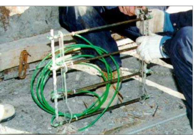
2.1 Special rebar ladders
Since the concrete cover to the standard rebars in the parapets is 75-mm thick, it may take time before salt and moisture penetrate and initiate corrosion. To permit the earliest possible corrosion detection, rebar ladders with four steel rebars (rungs) and two plastic rails (verticals) were designed and built at NRC and embedded in the parapet (Figure 4). Two sets were placed near the traffic-exposed surface of each test span of parapet. Each set consists of four parallel 10-mm rebars measuring 470 mm in length and spaced at intervals of 125 mm; the top rebar being 125 mm below the top of the parapet. These rebars, with extremities epoxy-coated, were mounted on the rigid plastic rails supported on the inner surface of the front form of the parapet. The rails were designed to hold the bars in a horizontal position, parallel to the surface of the parapet, with only 13 mm of concrete cover for the upper bar, and 25, 38 and 50 mm, respectively, for the others. A copper wire was welded to each rebar as well, running to the rear of the parapet to permit the measurement of corrosion potential and corrosion rate during the annual on-site tests. These rebar ladders received the same anticorrosion treatments as those used on the corresponding test span. For the control spans, epoxy-coated bars were used in span 12, and uncoated bars in span 21.
Innovations in Bridge Repairs
Monitoring Performance of Corrosion Inhibitors, Cusson
Figure 4: Special rebar ladder before installation in the parapet form
3 Field instrumentation
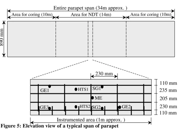
Readings are taken periodically by 80 sensors embedded in the concrete parapet. The use of embedded reference electrodes to monitor the electrochemical potential at different locations on the reinforcement allows the assessment of the corrosion activity in the parapet. Relative humidity (RH) and temperature sensors were installed inside and outside the parapet to determine the major environmental conditions which strongly affect corrosion. Embedded strain gauges were placed at key locations in the parapet to measure the deformation of the repaired structure.
The sensors were distributed along a 1-meter long section at the center of each of the 10 test spans (Figure 5). The manganese dioxide electrode is identified as ME, the graphite electrodes as GE1 to GE3, the RH and temperature sensors as HTS1 and HTS2, and the strain gauges as SG1 and SG2. Plastic rods/ties were used to secure sensors in place before casting so that no sensors are in contact with the rebars.
The sensors were connected to five data loggers which monitor them for the entire project. The data loggers (identified as DL in Figure 2) were programmed to take hourly readings from each sensor and store to a memory card the daily average, minimum and maximum. This data is transmitted wirelessly to computers in our labs via cellular modems included in the data loggers at the bridge.
More detail can be found in Cusson et al. (1998a) on the design and installation of the field instrumentation and the innovative remote monitoring used in this project.
Figure 5: Elevation view of a typical span of parapet
4 Field surveys
The baseline measurements for the study of the corrosion on the traffic-exposed face of the 10 spans of parapet were first performed in the spring 1997. A second set of measurements were taken a year later in the spring of 1998. Sets of measurements are planned for each of the next three years. Each survey consists of measuring the electrochemical potential and corrosion current of the steel reinforcement and of the special rebar ladders as well as the concrete resistivity.
The continuity of the steel reinforcement in the parapet is checked prior to any corrosion measurements. This check is performed on each span using copper wires previously welded to a minimum of four steel rebars which includes one top and one bottom horizontal bar and two vertical bars at the center of the test span. For every combination of two wires, the resistance and the potential difference is measured. Electrical continuity for a span is assumed if all combinations give a resistance less than 1 ohm and a potential difference less than 2 mV. Therefore, all steel rebars in the parapet were found to be electrically continuous except for those in spans 12 and 20 which are electrically isolated by the coating applied on bars before their assembly. Therefore all corrosion measurements performed in spans 12 and 20 are taken utilizing the wire attached specifically to the rebar being tested.
Area for NDT (14m)
Entire parapet span (34m approx. )
Area for coring (10m) Area for coring (10m)
890 mm
Instrumented area (1m approx. ) 230 mm HTS2 HTS1 GE1 GE3 GE2 ME SG1 SG2 110 mm 235 mm 205 mm 230 mm 110 mm
Innovations in Bridge Repairs
Monitoring Performance of Corrosion Inhibitors, Cusson
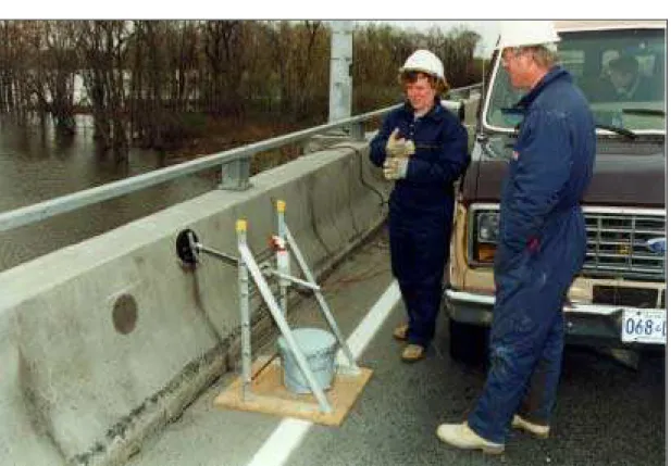
Figure 6: Annual corrosion survey of the parapet front face 4.1 Half-cell potential measurement
The electrochemical potential of the steel rebars in the parapet is measured against a Cu/CuSO4 reference electrode. Readings are taken vertically at 110, 345, 550 and 780 mm from the top of the parapet and horizontally at 300-mm intervals over the central 15-m section of each parapet span. Locations of transverse cracks located in the grid area are noted. Half-cell potential readings are also taken at the center point of each bar of the two special rebar ladders installed in every test span of parapet (Figure 4).
4.2 Corrosion current measurement
Corrosion currents are measured using the linear polarization technique and the Gecor 6 equipment with a guard ring (Figure 6). As the guard ring confines the current to a known area, accurate measurements of the current density can be made.
The random location of cracks in the parapet makes it impossible to keep the same relative test locations for all test spans. In each span, readings are taken on vertical and horizontal bars at cracked and uncracked locations. Tests are conducted at locations only where a single bar is present. The rebars selected for testing are located using measurements taken prior to concreting. Actual rebar locations are confirmed with a rebar locator.
4.3 Concrete resistivity measurement
Resistivity readings of the concrete are obtained using the Gecor 6 equipment and a special sensor supplied by the manufacturer. The readings are taken at the uncracked locations used for the corrosion current measurement.
4.4 Visual inspection
A visual inspection of the concrete parapet surfaces indicated that equidistant full height cracks through the cross-section of the parapet had formed within a few days of placing the concrete. The average longitudinal spacing of the macro-cracks were observed to be 810 mm. Inspection of bridges in the Montreal area has confirmed that such concrete cracking is not uncommon in rehabilitated bridge parapets. High, uneven stresses due to a combination of shrinkage, temperature variations and traffic vibrations may have exceeded the low tensile strength developed in the young concrete. The findings of a study focused on determining the underlying causes of the intense cracking of bridge parapets are presented in Cusson et al. (1998b). The importance of effects such as temperature variation, traffic vibration and shrinkage on the development of stresses causing cracking in concrete parapets was investigated through numerical analyses and field monitoring.
5 Laboratory experiments
5.1 Characterization of the field concrete
Laboratory tests are performed to determine the evolution over time of certain chemical, mechanical and physical properties of untreated concretes and of concretes treated with the corrosion inhibiting systems. The lab testing program includes the determination of the following properties at regular intervals: compressive strength, chloride content and profile, water and chloride permeability, mercury porosity, and freeze/thaw resistance.
An initial program of laboratory tests examined the principal characteristics of the concrete samples taken directly from the concrete mixer during pouring of each of the 10 parapet spans under study. After stripping, each sample was stored in a fog room (100% RH, 22˚C) until the time of the test.
A second program of laboratory tests examines the principal characteristics of concrete cores obtained from each of the 10 test spans of parapet. The cores are stored in the laboratory (50% RH, 22˚C) until the time of the test. Three cores were taken from the old slab in the center of each test span to permit characterization (chloride content and compressive strength only) of the old concrete in the slab below the new parapet. An additional three cores are taken annually in each test span of parapet to permit periodic characterization of the new concrete. The horizontal cores are taken at the mid-height of the parapet (traffic side) in a location as shown in Figure 5. The cores are long enough to provide a good number of samples (after cutting) for the different tests.
Innovations in Bridge Repairs
Monitoring Performance of Corrosion Inhibitors, Cusson
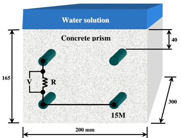
Figure 7: Typical reinforced concrete prism for accelerated corrosion lab study 5.2 Accelerated corrosion study
As a complement to the on-site testing, NRC is also conducting accelerated laboratory experiments on the corrosion-inhibiting systems under study. At least 80 reinforced concrete prisms (a minimum of 8 per test span) were cast on site and returned to NRC laboratories (Figure 7). The top and bottom rebars on the left were connected with a wire of a known resistance to permit the current measurement while the two bottom rebars were electrically connected with a copper wire to induce a corrosion cell. The concrete prisms are kept in a controlled environment (50% RH, 22°C) and submitted to wet/dry cycles for periods of 28 days. Measurements of the electrochemical potential and the linear polarization resistance are taken monthly to monitor the corrosion progression with time.
In addition to furnishing useful supplementary information on the performance of each corrosion-inhibiting system, this on-going laboratory study will permit assessment of the practice of pairing epoxy-coated and uncoated bars in the same concrete unit (40 prisms were constructed with 2 regular rebars near the top face and 2 epoxy-coated rebars near the bottom). Transportation departments often mix coated and uncoated bars when repairing concrete bridges, a practice that may accelerate rebar corrosion.
R
R
2 20000mmmm 1 16655 3 30000 4 400V
V
1
15
5M
M
W
W
a
a
t
t
e
e
r
r
s
s
o
o
l
l
u
u
t
t
i
i
o
o
n
n
C
Co
o
n
n
cr
c
re
et
te
e
p
p
ri
r
is
sm
m
6 Summary
The monitoring strategy selected for this bridge repair project is to provide field data on the long term performance of the rehabilitated concrete parapets and to ensure that the long term durability of the structure has been enhanced by the rehabilitation measures. This is achieved by remote sensing of the condition and performance of the rehabilitated parapet, by taking extensive annual corrosion surveys on site, and by conducting supporting lab experiments.
The use of field instrumentation and remote data loggers equipped with cellular modems allows accurate real-time monitoring of the long-term field performance of the rehabilitated parapet. This innovative technology is extremely useful for bridges remote from the laboratory or for busy highway bridges on which the traffic can not be disrupted.
This on-going investigation of corrosion inhibiting systems will assist manufacturers to improve understanding of product performance in the field and further development of the products. It will also contribute to improved bridge repair techniques via long-term performance data, which transportation agencies look for when selecting products.
7 Acknowledgements
The National Research Council of Canada wishes to thank its partners for their contributions to the project, in particular: the Ministry of Transportation of Quebec, Axim Concrete Technology, Caruba Holdings, Euclid Admixture Canada, Israel Richler Trading, Master Builders Technologies, Sika Canada, and W.R. Grace & Co.
8 References
Cusson, D., Taylor, D., Glazer, R., and Arnott, M. (1998a). Remote sensing of the performance of a repaired concrete highway bridge, International Conference on Corrosion & Protection of Concrete Structures, Orlando, 15 p. (accepted) Cusson, D., Repette, W., Glazer, R., Taylor, D., and Mailvaganam, N. (1998b).
High-early stress and premature cracking of reconstructed concrete bridge parapets, 26th CSCE Annual Conference, Halifax, Vol. IIIb, pp. 683-692. Mirza, S., Shao, Y., and Collinge, J.P. (1998). Post-mortem of the abandoned
Dickson bridge, 26th CSCE Annual Conference, Halifax, Vol. IIIb, pp. 753-762.
Seabrook, P.T. and Hansson, C.M. (1996). Applications of in-situ corrosion monitoring in HPC structures, Concrete Canada Technology Transfer Symposium, Moncton, 23 p.