HAL Id: hal-01816334
https://hal.archives-ouvertes.fr/hal-01816334
Submitted on 15 Jun 2018
HAL is a multi-disciplinary open access
archive for the deposit and dissemination of
sci-entific research documents, whether they are
pub-lished or not. The documents may come from
teaching and research institutions in France or
abroad, or from public or private research centers.
L’archive ouverte pluridisciplinaire HAL, est
destinée au dépôt et à la diffusion de documents
scientifiques de niveau recherche, publiés ou non,
émanant des établissements d’enseignement et de
recherche français ou étrangers, des laboratoires
publics ou privés.
Two Industrial Reports
Cl´ement Duffau1,2, Thomas Polacsek3, and Mireille Blay-Fornarino2
1 AXONIC, Sophia Antipolis, France
2 Universit´e Cˆote d’Azur, I3S, CNRS UMR 7271, France
3 ONERA, Toulouse, France
Abstract. The result of productive processes is commonly accompanied by a set of justifications which can be, depending on the product, process-related quali-ties, traceability documents, product-related experiments, tests or expert reports, etc. In critical contexts, it is mandatory to substantiate that a product’s devel-opment has been carried out appropriately which results in an inflation of the quantity of justification documents. This mass of document and information is difficult to manage and difficult to assess (in terms of soundness). In this paper, we report on the experience gained on two industrial case studies, in which we applied a justification elicitation approach based on justification diagrams and justification pattern diagrams in order to identify necessary and sufficient justifi-cation documentation.
Keywords: Requirements elicitation, Justification, Certification, Requirements engineering, Quality requirements
1
Introduction
In critical contexts, it is usual to provide documentation to explain why product devel-opment is trustworthy. Here, we use the term critical in a very general sense: it qualifies an activity that may have very negative consequences for a product development or for a project. In this context, the purpose of this documentation is to convince that develop-ment process has been managed correctly and/or the design process properly followed a standard. It is not the matter to convince the customer about the features of the final product, but to convince the accreditation client that he cans be confident in the final product. An accreditation client can be a project manager, certification authorities or the client of the product. Unlike a usual final customer who will focus on product require-ments regardless of the chosen development methodology, the accreditation client is mainly concerned by the achievement of quality requirements.
We can draw a parallel between the accreditation client’s activities and activities in the field of simulation. Thus, Verification, Validation and Accreditation (VV&A) [2] defines an accreditation activity that involves an authority to certify that a model or simulation can be used for a specific usage. To this end, it is necessary to have com-prehensive documentation, a set of justifications, explaining not only the results but also input data, hypotheses, applied techniques, etc. The accreditation activities, or the certification activities, consist to collect and evaluate this documentation.
capitalize on the strategies that have been followed to obtain these justifications. In [24], Polacsek introduced a new kind of diagram, namely the Justification Dia-gram(JD)4, to support accreditation and certification activities. The JD allows to
orga-nize in diagram form the various elements, formal and informal, that contribute to the justification of a result. It shows the rationale of the documentation and presents this information in a comprehensive way.
In this article, starting from the definition of JD given in [24], we will introduce a new concept: Justification Pattern Diagram (JPD), which is an abstraction of JD (cf. Section 2). Through two industrial reports, whose domains, objectives and life cy-cles are very different, we explain how we used these diagrams to elicit justifications. A medical technologies use case, in Section 3, focuses on certification of software in medical devices in the context of agile development and conformance to several tangled standards. In Section 4, an aeronautic use case focuses on a strategic decision totally in-dependent of certification purpose but requiring confidence. In Section 5, we compare our approach to related work and Section 6 is dedicated to lessons learned. Section 7 concludes and gives some perspectives.
2
Justification Diagrams and Justification Pattern Diagrams
2.1 Justification Diagrams (JD)
Justification Diagrams come from argumentation theory, specifically from the Toulmin argumentation schema [27]. The aim of JD is to define a comprehensive notation to explain why a result is trustable. It captures the rationale logical structure of all evidence that leads to the acceptance of a high-level property. On the top, there is a conclusion and, on the bottom, the leaves are the evidences that lead to the conclusion. Actually, a JD is the juxtaposition of reasoning steps, where a reasoning step is the transition from supportsto a conclusion, as presented in [24].
4In the first version, these diagrams are called the Argumentation Diagram, but to avoid any ambiguity with dialogical argumentation, we chose to use the term Justification Diagram.
The cornerstone of this model is the notion of strategy. The strategy is the inference relation, it explains clearly how, from supports, it is possible to infer a conclusion. Examples of strategies are: an expert committee review, the application of a standard, the use of software or the validation by an expert. To understand what underlies the strategy and why the strategy is acceptable, two concepts are added: (a) rationale, the justification for why guarantees are acceptable, and (b) usage domain, contexts in which the strategy can be applied.
Note that, in a project, JD is built alongside of a development process that accom-panies the various stages of Verification and Validation activities: it is constructed by aggregating artefacts (e.g. documents, spreadsheets, simulation). Experiments on the use of JDs have already been conducted in various aeronautical case studies [24, 3] and integrated in a software in the context of medical experimental studies [8].
2.2 Justification Pattern Diagrams (JPD)
In this article, we extend the concept of JD presented in [24] with Justification Pattern Diagrams. JPD is an abstraction of JD, it designs the expected JDs. Indeed, before starting a project, identifying what is needed in terms of justifications is crucial.
Designing JPDs is a complex task. In fact, it requires a global vision of the process, a good knowledge of the applicable standards, the definition of the expected usages of the product and it relies on previous means of justification. By means of JPD, experts reason on the type of artefacts (e.g. tests coverage, requirements) more than on the documents themselves (e.g. Jacoco document results, Business Requirements Document). When a JD results of a day-to-day justification process, a pattern-diagram is a canvas more or less strict that gives a guide to conduct a project in terms of justifications.
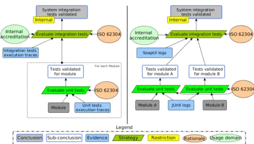
An example of JPD and JD is given in Figure 1. On the left side of the Figure, the JPD gives, in an abstract way, the justification for software integration tests in a medical context. To validate this integration, the traces of the integration tests is required and tests for each module must be validated. This validation is carried out in compliance with the standard IEC 62304 which describes acceptable software life cycle processes and activities in medical. The JD, on the right side of the Figure, conforms to this JPD. All required elements by the standard are present in the JPD. For instance, the unit tests execution traces(respectively integration tests execution traces) correspond to JUnit logs, (respectively SoapUI logs). To assess on the system integration tests validity, with-out the approval of the accreditation client, the conclusion must be limited to internal purposes. This restriction can only be lifted when an external audit is conducted.
The next two sections show how we used these diagrams in two industrial reports. As Franch and al. highlighted in [11], we try to fill the gap between academic research, practitioner and regulatory adoption by driving our research thanks to the following two industrial use cases. The first case study is part of an agile development process and the use of JDs for justification requirement elicitation relies on case reasoning [21]. The second case study is part of a V-Model development lifecycle and relies on a priori design.
Fig. 1. Justification Pattern-Diagram (JPD) on right and the associated Justification Diagram (JD) on left in the context of automated tests execution.
3
Application in a Healthcare Company to Software Certification
Purpose
3.1 Context
AXONIC is a young company including a dozen people, founded in 2014. It devel-ops neurostimulation devices to address different pathologies bounded to the nervous system. According to the destination of the devices, the AXONICs development pro-cess has to be compliant with different standards. For instance, the standard IEC 62366 is a general canvas that takes care about summative evaluation, user training and user documentation in a general medical context. Additionally to this standard, for a medical product used at the patient’s home, the collateral standard IEC 62366-1 must also be ful-filled too: it introduces especially error-prone aspect, e.g., physical security to prevent a child to be able to use the device. AXONIC has also to apply standards relating to hard-ware and softhard-ware development, e.g. ISO 13485 that describes regulatory requirements on quality management system and IEC 62304 that gives a canvas of development for software in medical equipment.
In this case study, we focus on attesting conformity for clinical studies delivery dedicated to software. To this end, a set of documents has to be produced in order to ensure confidence in the product and in the development process. Guidelines can be found to help development processes to be compliant with applicable European stan-dards [1]. These guidelines compile practices and provide tools to support the applicants in producing the appropriate evidence of compliance, i.e. the justifications. Thus, stan-dards (e.g. ISO 14971 refined in IEC 62304 and IEC 62366) lead to complex tangled justification activities. Moreover, application contexts of medical standards can be so diversified and so complex that AXONIC wants to reuse justification patterns and
cap-italize on them in other projects, so that to avoid repeating the recurrent tasks several times.
In addition to technical standards, development cycle standards has to be applied. For instance, in the context of this study, we apply Agile development cycle, this devel-opment process is described in the AAMI guidance [1].
The elicitation of justification requirements is carried out at the kick-off of the project and takes into account the applicable standards and guidelines. We show, in the next subsections, how we use JPDs and JDs to elicitate the justification artefacts and their dependencies throughout the development of a new device.
3.2 Justification Requirements Elicitation
In this case study, the stakeholders involved for the justification parts are: one resear-cher/practitioner (PhD student), a quality management team (two people) and techni-cal leaders (three people). The quality team is responsible for standard’s watchfulness, design process, audit preparation, etc. The technical leaders ensure that justifications planned in the process are properly produced and defend these justifications in audits. To conduct the study, the researcher is included in day-to-day activities from meetings (e.g. project monitoring, risks analysis assessment, technical meetings and audits) to system production itself.
After one year of involvement in AXONIC, the researcher designed a preliminary JPD for a new project, based on company’s practices (see Figure 2). Then, during the next year, the researcher, the quality management team and the technical leaders iter-ated to produce justifications, improve this JPD and take into account new applicable standards. To build the JPDs at each stage of the development project, the team has iterated on the basis of the following process:
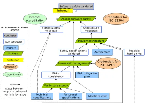
1 Before starting the development of a new stage, the researcher designs a JPD ac-cording to quality management team and technical leader requirements. This new JPD can be a refinement of the JPD of the previous step, for instance, in order to include new applicable standards. For example, The JPD in Figure 3 is a revision of the JPD described in Figure 2. At this step, to assess software safety, it is mandatory to have the architecture of the device validated. As shown on the diagram, this val-idation is carried out by a review which corresponds to the addition of the strategy: Review architecture. This architecture review requires previous justifications about feasibility review. Moreover, to conform to standard ISO 14971 new justification steps have been added to asses risk management. IEC 62304 and ISO 14971 are tangled in terms of software risk analysis. Thanks to JPD, we identify the previous artefacts that can be shifted to answer to these new requirements but also identify missing justifications.
2 Technical leaders (i) identify justification items that must be produced and (ii) develop tools to produce them (e.g., extracting documents from the production toolchain, adding a plug-in to existing tools) [9]. Based on the JPD, a JD is created. If a JD from the previous iteration exists, common elements are automatically pop-ulated in the new JD by copying the elements present in the previous one. If there is no diagram of the previous iteration, all justifications artefacts will have to be produced during the stage.
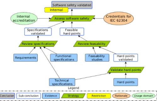
Fig. 2. JPD illustrates the result of kick-off of a new project. Requirements must lead to func-tional and technical specifications that must be reviewed to be validated. Due to this refinement, technical hard points are found and feasibility studies need to prove that they can be overcome.
3 During the development stage, technical leaders eventually define new activities, such as expert validation, committee review or external tests and the development team produces the necessary justifications of the JD. Indeed, while the development process evolves, new justifications or ways to justify appear. So, they are added to the current JD. Note that, at this point, we have a shift between the expectations designed in the JPD and the reality captured by the JD.
4 At the end of the development stage, Quality team and researcher analyze the dif-ference between the JPD and the JD. The comparison helps to identify (i) missing justifications that must be produced and (ii) new artefacts that must be introduced as justification requirements in the JPD. After a deep analysis on the reason of oc-currence of these differences, we can align the JD on the JPD: refute real-world practices, or align the JPD on the JD: accept real-world evolution. For example, during the project, AXONIC introduced the standard IEC 62366 in their practices. While producing justifications, we noted that documents produced for ISO 14971 and for IEC 62366 was actually much easier to produce together than in a separate way. This fact, different from what expected in the JPD, leads us to integrate this practice in the JPD.
During this study, we designed five JPDs, for the five main stages of the project, and we used these JPDs to produce an associated JD at each project iteration. We also ver-sioned JPDs and JPs in the same way that the source code. In fact, it is useful to attest of good practices during all the development process and to retrieve state of justifications at each stage of the project. In the future, these JPDs will be reused as an initial input for
Fig. 3. Project stages further, this JPD keeps supports defined by the previous stages and adapts it to match new requirements of the current stage.
new projects. Moreover, other JPDs will be designed for other domains (e.g., hardware, mechanics) and finally to justify all quality requirements met a such system.
4
Application in an Aircraft Manufacturing to Workload
Assessment Purpose
4.1 Context
To ensure that production costs are not taken into account too late in the aircraft design processes, it is crucial to perform an assessment of these costs at the early stages of the design. With this assessment, production costs could become one of the selection criteria among different possible aircraft designs as well as the mass, the noise, the thermal efficiency, etc. To do so, it is necessary to establish a strong interaction between the design engineering and the production and, therefore, to be able to perform a reliable assessment of the workload for a given design [25].
The current workload assessment is based on a very detailed design and requires several complex and time-consuming computations. To get a faster estimation, at the cost of a less reliable assessment, a new process has been defined. To remain in line with the aircraft manufacturer’s practice, this process has to be part of a V cycle. It starts at very preliminary design and finishes with advanced design, and reuses previous results from one stage of a cycle to the next as much as possible. Confidence is gained at each
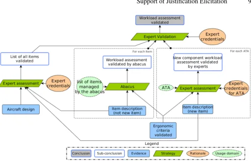
Fig. 4. Justification Pattern-Diagram at stage 1
step of the process. With this process, it is possible to assess the workload very quickly, in the preliminary phase, with little information and a lot of uncertainty. This workload assessment process is based on steps and a new assessment is made at each step.
The computation of workload assessment is very critical. A lot of decisions could be taken with this information, such as design choices, but also manpower allocation, cost assessment, etc. We used JPDs to have a better understanding of evidence on which this assessment is based on and clearly identify the necessary validation operations to have confidence in the final result.
4.2 Justification Requirements Elicitation
JPD are used to define the documentation and the list of justifications, in order to have a reliable process and to perform justification requirements elicitation. In this context, JPD is useful: firstly, to define the list of necessary evidence for this new workload assessment process; secondly, to identify activities required for justification (activities that will be added to the process afterward).
Therefore, we use the JPD to understand the rationale on workload assessment com-putation and to identify the evidence that must be produced at each step of the process. The diagrams we introduce are a very simplified version of our final diagrams. We chose, for legibility and confidentiality reasons, to skip some minor details which do not contribute to the understanding. Moreover, in this case study, we worked on the aircraft modifications (design changes), so on the additions as well as the removals of components, but we chose to focus here only on the additions.
At the beginning of this study, we focused on understanding the process of how manufacturing departments perform workload assessment. For this end, we interviewed aircraft architects, workload experts and people who are involved in the workload
as-Fig. 5. Justification Pattern-Diagram at stage 2
sessment process. We also spent two days on the assembly line to gain first-hand knowl-edge of their approaches.
From there, we made guileless JDs to represent what could be a good justification for a concrete example. Then, we refined these JDs with the different actors and we converged on three diagrams. Having three diagrams means that the process is in three steps. Indeed, each JD represents an accreditation step, a step where the workload as-sessment value must be justified. This process should describe the production activities of justification artefacts present in JDs.
Finally, on the basis of these these JDs, we developed the JPDs, which were also confronted against reality and approved regarding practice feedbacks. In the first stage, when we have a very preliminary aircraft design, an abacus software is used to compute workload assessment (see Figure 4). The usage domain of this software is the list of aircraft parts known by the software. The confidence in this assessment is based on the confidence we have in the software: we thus have a strategy based on the abacus software. If an aircraft’s part is not in the abacus (right part of the Figure 4), for instance it is a new component, then the workload assessment is performed by a workload expert. This assessment is done by an expert and there is an expert for each ATA5). Doing this
JPD allowed to highlight, in a first version, the need to have an expert of the assembly line that validates the result of the software and, in a second time, that this expert also needs to validate the calculation carried out by the workload expert. In our diagram, this validation is the strategy to pass from the workload assessments to the final conclusion:
5ATA chapters are defined by the Air Transport Association of America. It is a common ref-erencing standard for all commercial aircraft documentation. An ATA chapter represents a aircraft domain like Air Conditioning & Pressurization (ATA 21), Electrical Power (ATA 24) or Pneumatics (ATA 36).
Fig. 6. Justification Pattern-Diagram at stage 3
the workload assessment is validated. This strategy introduces a new activity, an expert validation, which must be added to the workload assessment process.
In the second stage (see Figure 5), all previous justifications are kept but strategies are enriched to enforce confidence. In this stage, the aircraft design is more detailed, we must therefore have the complete list of elements, nothing should be missing. This ver-ification introduces a new element, the list of all items is validated, which is guaranteed by an expert. So, the confidence in the accuracy of the list is based on the trust on the component expert. Finally, to increase confidence in the final result a new document is used: the workload impact of ergonomic criteria.
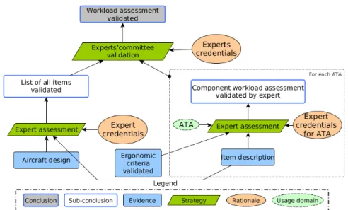
In the last stage (see Figure 6), the two most important points are: the introduction of an experts committee and the removal of the abacus software. Here, we have an ad-vanced aircraft design and this is the last step before crucial decisions are made. Thus, all workload assessment needs to be performed by an expert and not by a machine. In the first version of this diagram, we had not changed the top validation strategy (“Ex-pert validation” see Figure 5), but it appeared that, given the critical nature of the final result, all the calculations had to be validated by an experts’ committee. Note that, the committee valid not only the workload assessment, but also the list of parts. The characterization of usage domain and rationale for the strategy “experts’ committee val-idation” was an opportunity to clearly define the members, the roles and the credentials of this committee.
5
Related Work
Close to our work, some methods use a goal-oriented approach to support requirement elicitation and organization. Language and methodology like KAOS [17], i* [7] and globally all the Goal-oriented Requirements Languages (GRL) tackle challenges like
evolution of requirements but also internal practices with a goal-oriented approach [20] and also are focused on accreditation client requirements [19]. All these goal modeling languages focus on who and what, but they do not try to capture the why. To fill this gap, Van Zee and al. introduce a complementary approach between GRL and argument diagrams to capture the rationale of goal models inside mapped argument diagrams [28]. They add a representation of arguments pros and cons a system modeled with i*. Contrary to us, they focus on the justification of a choice versus alternatives and not on the justification that this choice is compliant with some standards.
In the field of knowledge organization, a numerous of methodologies are argumen-tation based. They all have the same root: Issue-Based Information Systems (IBIS) [16]. IBIShas been designed to support and to document decision processes, but it is now used to organise knowledge and justification ([14] presents a set of case studies and commentaries on how IBIS is used in practice). All the notations coming from IBIS have in common to try to capture the rationales behind the decisions taken during a design process, as well as the different alternatives that have finally failed. For example, the Questions, Options and Criteria(QOC) [18] approach identifies design problems with questions and alternatives with possible answers. In addition, QOC has an evaluation criteria based on requirements and desired properties. With these evaluation criteria, it is possible to rank different options.
However, all this approaches are designed for the early phases of development, for the design and for design choices. On our side, we address a somewhat different prob-lem, while we are interested in the acceptance of a product and not in alternatives. It is therefore no longer a question of keeping track of the alternatives, but of trying, as finely and formally as possible, to explain the reasons and the context why a product is trustable.
In safety, two notations have been imposed to present justifications and valid argu-ments to convince that a system satisfies safety properties: the Goal Structuring No-tation(GSN) [13] and Claim-Argument-Evidence (CAE) [10]. Even if historically the GSN and CAE were based on the Toulmin schema, nowadays it is no longer true [5]. For Toulmin, the strategy is the cornerstone of reasoning, it gives the reasons why it is possible to pass from supports to a conclusion. In GSN and CAE, strategy is optional. It is possible to jump directly from supports to a conclusion, without usage domain and justification, without explanation. By doing this a large part of the rationale is lost. In addition, both notations are very safety oriented and are not appropriate for a generic purpose.
Finally, we can cite the OMG initiative which aims to establish a meta-model for assurance case called SACM for “Structured Assurance Case Metamodel” [23]. In this standard, the OMG captures the key concepts of assurance case to structure them in a conceptual model. Therefore, this representation can be applied as the baseline of automation, checks, integration with other tools and also evolutions [12]. For us, the purpose is the same but we introduce in this article a higher level of abstraction. In contrary to SACM that reasons at the assurance case instance level (for us JD), we introduce JPD to design template that can be seen as assurance case templates. Even if the community is adopting the envision of templates, there are still domain centric [6] and not presented in a global approach that can be introduced in SACM.
JPD Makes the Link Between Verification and Validation (V&V) and Justification Re-quirements. The relationship between quality requirements and JPDs relies currently on the expertise of quality managers. In the case of the Aircraft Manufacturing applica-tion, establishing this relationship was the essential part of the work. As we have seen in this case study, the JPD captures the results of the V&V activities, and therefore cap-tures V&V requirements. However, a systematic check of the alignment between model of quality requirements, like i* [7], remains a perspective to this work.
JPD Design Requires an Iterative Process. The construction of JPDs is strongly depen-dent on: the maturity of teams, the aims of the projects (e.g. prospective, production) and the development cycle. In our two experiments, teams must refine the JPDs ac-cording to the stages of the project. For cost and progress management purposes, all justifications cannot be required at the beginning of a project. Some of them need to be added or refined along the lifecycle and, sometimes, justification activities must be added during development for instance when an artefact requires justifications that were not be anticipated. Thus, the construction of JPDs is an iterative process in which not only quality experts but also all stakeholders must be involved.
The Two Reports Focus on Long-term Projects in Different Fields. Both reports fo-cus on different contexts that involve different standards and usages. However, they both correspond to long-term projects. As a result, teams could not yet reuse JPDs in the production of other products. However, the iterative nature of the projects treated showed the interest of reusing the JPDs from stage to another. The contexts of the stud-ies also differ in one case by integrating the researcher into the team and, in the other case, by the use of an external consultant. In both, JPDs have proven to be very useful for discussions with all stakeholders.
JDs Help to Manage Justifications
As we have seen, the JD elements are connected to artefacts of justification, like for in-stance a report or a minutes. Therefore, a JD can be considered as a means to organize
the justification documents. Note that, in the aeronautic experiment, JDs are built infor-mally using the JPDs as a guide and they are built with tools in the medical experiment. JDs Provide a Global Justification Based on Justification Artefacts. In the medical application, JDs refer to the artefacts stored in a data base, the Electronic Document Management. From the JD, we were able to generate automatically a textual document of justification: the Master File. The Master File is the document that quality auditors are used to use. In this project, the quality auditor was very enthusiastic the use a navi-gable JD instead of the Master File. However, for the highly regulated activities, it does not seem possible today to work only with the JD, without Master File, which repre-sents an excessively important breakthrough. Nevertheless, according to the team and to the quality auditor, we get a significant benefit by automatically having artefacts up-dated and referenced in JD, and the ability to generate the expected auditing document is quite promising.
JDs Support the Confidence in Product Justifications. Because JPDs may be seen as a structured guideline, a detailed check list of all needed justification artefacts, they relieve development teams from missing something necessary for the product compli-ance. For instance, the validation by the quality team that a JPD captures all the stan-dards requirements allows the development team to focus on the development, not on the standards. In addition, JPDs could support the production of justification artefacts. For instance, in the medical experiment, automating the production of several artefacts using tools for continuous integration is one of the key elements of this confidence [9]. Once the tools are configured, they produce always consistent artefacts contrary to humans that are error-prone.
Experiment Context Could be a Threat to Validity. In both experiments, the construction of the JD was done by small teams. We have not tested our approach on large teams, for instance with people specialized in specific quality aspects (e.g. prototyping, clinical studies, CE marking). We don’t know what the results would have been on larger teams. Moreover, while AXONIC constructs an evolving JPD during the project devel-opment, aircraft manufacturer constructs different JPDs based on old projects. This is mainly due to a difference of maturity level between the two industries. AXONIC tries to adopt Agile practices and needs to redefine their justification process, while aeronau-tic industry can monitor previous projects to predict the next one. Thus, it is difficult to establish a standardized methodology for JPD. However, with these two complete different use cases, we can assert that, regardless of the maturity level of the company and the life cycle model, for small teams JPDs are useful.
7
Conclusion and Perspectives
In this article, we have shown, through two industrial case studies, that it is possible to use JPDs and JDs to perform justification elicitation. Projects in aeronautics and medical are long-term developments, so, these projects are still in development and we continue to monitor usage of these notations. Still, feedbacks from industrial partners are good enough to say that we are confident for the validation in long-term usage.
data-set. Here, the key point for the adoption of this platform is to convince data mining experts that: there is no bias, no gap in the experiments or that the initial experiments protocol has been followed.
Finally, in our experiments, the use of JD and JPD highlight the links between jus-tifications and activities to produce justification. It might be interesting to make the connections between our diagram and existing notations like BPMN [22] or i* [7]. We think that integration of Justification Diagrams into common industrial technologies, like Continuous Integration platforms and Document Management Software, is a key point to industry interest. To address these technologies, automation around Justifica-tion Diagrams must be extended.
References
1. AAMI, A.T.: Guidance on the use of agile practices in the development of medical device software. Association for the Advancement of Medical Instrumentation (2012)
2. Balci, O.: Verification, validation, and accreditation. In: Proceedings of the 30th conference on Winter simulation. pp. 41–4. IEEE Computer Society Press (1998)
3. Bieber, P., Boniol, F., Durrieu, G., Poitou, O., Polacsek, T., Wiels, V., Martinez, G.: MI-MOSA: Towards a model driven certification process. In: Proc. 8th Int. Congress on Embed-ded Real Time Software and Systems (ERTS’16) (2016)
4. Camillieri, C., Parisi, L., Blay-Fornarino, M., Precioso, F., Riveill, M., Cancela Vaz, J.: To-wards a Software Product Line for Machine Learning Workflows: Focus on Supporting Evo-lution. In: Proc. 10th Work. Model. Evol. co-located with ACM/IEEE 19th Int. Conf. Model Driven Eng. Lang. Syst. (MODELS) (October 2016)
5. Cassano, V., Maibaum, T.S.E.: The definition and assessment of a safety argument. In: 25th IEEE International Symposium on Software Reliability Engineering Workshops, IS-SRE Workshops. pp. 180–185. IEEE Computer Society (2014)
6. Chowdhury, T., Lin, C.w., Kim, B., Lawford, M., Shiraishi, S., Wassyng, A., Division, S., View, M.: Principles for Systematic Development of an Assurance Case Template from ISO 26262. In: ISSREW 2017 (2017)
8. Duffau, C., Camillieri, C., Blay-Fornarino, M.: Improving confidence in experimental sys-tems through automated construction of argumentation diagrams. In: ICEIS 2017 (2017) 9. Duffau, C., Grabiec, B., Blay-Fornarino, M.: Towards embedded system agile development
challenging verification, validation and accreditation : Application in a healthcare company. In: ISSREW 2017 (2017)
10. Emmet, L., Cleland, G.: Graphical notations, narratives and persuasion: a pliant systems approach to hypertext tool design. In: Blustein, J., Allen, R.B., Anderson, K.M., Moulthrop, S. (eds.) HYPERTEXT 2002, Proceedings of the 13th ACM Conference on Hypertext and Hypermedia. pp. 55–64. ACM (2002)
11. Franch, X., Fern´andez, D.M., Oriol, M., Vogelsang, A., Heldal, R., Knauss, E., Travassos, G.H., Carver, J.C., Dieste, O., Zimmermann, T.: How do practitioners perceive the relevance of requirements engineering research? an ongoing study. arXiv:1705.06013 (2017) 12. Gonz´alez, V., G´enova Fuster, G., ´Alvarez Rodr´ıguez, J.M., Llorens Morillo, J.B., et al.:
An analysis of safety evidence management with the structured assurance case metamodel (2017)
13. Kelly, T., Weaver, R.: The goal structuring notation/- a safety argument notation. In: Proc. of Dependable Systems and Networks 2004 Workshop on Assurance Cases (2004)
14. Kirschner, P.A., Buckingham-Shum, S., Carr, C.S.: Visualizing Argumentation : Software Tools for Collaborative and Educational Sense-Making. Computer Supported Cooperative Work, Springer (2003)
15. Knauss, E., Liebel, G., Schneider, K., Horkoff, J., Kasauli, R.: Quality requirements in agile as a knowledge management problem: More than just-in-time. In: 2017 IEEE 25th Interna-tional Requirements Engineering Conference Workshops (REW). pp. 427–430 (2017) 16. Kunz, W., Rittel, H.: Issues as elements of information systems. Working Paper 131, Institute
of Urban and Regional Development, University of California, Berkeley, California (1970) 17. van Lamsweerde, A.: Requirements Engineering - From System Goals to UML Models to
Software Specifications. Wiley (2009)
18. MacLean, A., Young, R.M., Bellotti, V.M.E., Moran, T.P.: Questions, options, and criteria: Elements of design space analysis. Hum.-Comput. Interact. 6(3), 201–250 (Sep 1991) 19. Massey, A.K., Holtgrefe, E., Ghanavati, S.: Modeling regulatory ambiguities for
require-ments analysis. In: International Conference on Conceptual Modeling. Springer (2017) 20. Nguyen, C.M., Sebastiani, R., Giorgini, P., Mylopoulos, J.: Requirements evolution and
evo-lution requirements with constrained goal models. In: 35th International Conference, ER 2016. pp. 544–552. Springer (2016)
21. Nisbett, R.E.: Rules for reasoning. Psychology Press (1993)
22. OMG: Business Process Model and Notation (BPMN), Version 2.0 (January 2011) 23. OMG: Structured assurance case meta-model (sacm) (2013)
24. Polacsek, T.: Validation, accreditation or certification: a new kind of diagram to provide confidence. In: 10th IEEE International Conference on Research Challenges in Information Science, RCIS,. pp. 59–466 (2016)
25. Polacsek, T., Roussel, S., Bouissiere, F., Cuiller, C., Dereux, P., Kersuzan, S.: Towards think-ing manufacturthink-ing and design together: An aeronautical case study. In: Mayr, H.C., Guiz-zardi, G., Ma, H., Pastor, O. (eds.) Conceptual Modeling - 36th International Conference, ER 2017. vol. 10650, pp. 340–353. Springer (2017)
26. Rempel, P., M¨ader, P., Kuschke, T., Cleland-Huang, J.: Mind the gap: Assessing the confor-mance of software traceability to relevant guidelines. In: Proceedings of the 36th Interna-tional Conference on Software Engineering. pp. 943–954. ICSE 2014, ACM (2014) 27. Toulmin, S.E.: The Uses of Argument. Cambridge University Press, Cambridge, UK (2003),
updated Edition, first published in 1958
28. Van Zee, M., Marosin, D., Bex, F., Ghanavati, S.: Rationalgrl: A framework for rational-izing goal models using argument diagrams. In: Conceptual Modeling: 35th International Conference, ER 2016. pp. 553–560. Springer (2016)