Publisher’s version / Version de l'éditeur:
Vous avez des questions? Nous pouvons vous aider. Pour communiquer directement avec un auteur, consultez la première page de la revue dans laquelle son article a été publié afin de trouver ses coordonnées. Si vous n’arrivez pas à les repérer, communiquez avec nous à PublicationsArchive-ArchivesPublications@nrc-cnrc.gc.ca.
Questions? Contact the NRC Publications Archive team at
PublicationsArchive-ArchivesPublications@nrc-cnrc.gc.ca. If you wish to email the authors directly, please see the first page of the publication for their contact information.
https://publications-cnrc.canada.ca/fra/droits
L’accès à ce site Web et l’utilisation de son contenu sont assujettis aux conditions présentées dans le site LISEZ CES CONDITIONS ATTENTIVEMENT AVANT D’UTILISER CE SITE WEB.
Client Report (National Research Council of Canada. Institute for Research in
Construction), 2008-03-18
READ THESE TERMS AND CONDITIONS CAREFULLY BEFORE USING THIS WEBSITE.
https://nrc-publications.canada.ca/eng/copyright
NRC Publications Archive Record / Notice des Archives des publications du CNRC :
https://nrc-publications.canada.ca/eng/view/object/?id=45778707-13d0-48bb-b4cd-82fd054455a0 https://publications-cnrc.canada.ca/fra/voir/objet/?id=45778707-13d0-48bb-b4cd-82fd054455a0
Archives des publications du CNRC
For the publisher’s version, please access the DOI link below./ Pour consulter la version de l’éditeur, utilisez le lien DOI ci-dessous.
https://doi.org/10.4224/20374945
Access and use of this website and the material on it are subject to the Terms and Conditions set forth at
Evaluating the effectiveness of wall-window interface details to
manage rainwater Phase 1 - watertightness, air leakage and rainwater
management of CMHC specified assemblies
Lacasse, M. A.; Rousseau, M. Z.; Cornick, S. M.; Manning, M. M.; Nicholls,
M.; Nunes, S. C.
Performa nc e Eva luation of Wall-Window
Inte rfa ce Deta ils Phase 1 – Watertightness,
Air Le ak a ge and Rainw ater M ana gement
of CM HC Specifie d Assem blies
R E P O R T: B - 1 2 2 9 . 1
A Client Report based on the results of the
broader Joint CMHC / IRC Research Project on:
Evaluating the Effectiveness of Wall-Window
Interface Details to Manage Rainwater
for the
Canada Housing and Mortgage Corporation
700 Montreal Road
Ottawa, Ontario
K1A 0R6
Evaluating the Effectiveness of Wall-Window
Interface Details to Manage Rainwater
Phase 1 – Watertightness, Air Leakage and
Rainwater Management of CMHC Specified
Assemblies
Author
Dr. M. A. LacasseAuthor
Ms. M. RousseauAuthor
Mr. S. M. CornickAuthor
Ms. M. ManningAuthor
Mr. M. NichollsAuthor
Mr. S. NunesQuality
Assurance
Dr. A. H. Elmahdy
Approved
Dr. R.M. Paroli
Director, Building Envelope and Structure Program
Report No: B-1229.1
Report Date: 18 March 2008 Contract No: B-1229
Program: Building Envelope and Structure
218 pages Copy No. 1 of 15 copies This report may not be reproduced in whole or in part without the written consent of both the client and the National Research Council Canada
Table of Contents
Table of Contents………. iii
List of Figures……… v List of Tables……… x Nomenclature……… xi Acknowledgements………. xiii Preface……… xv Executive Summary………xvii
Chapter 1 – Introduction and Approach to Performance Assessment of Wall-Window Assemblies Chapter 2 – Description of Test Specimens – An Overview
Chapter 3 – Development and Rationale for Test method and Summary of Test Protocol Chapter 4 – Results and discussion from tests on Specimen W1
Chapter 5 – Results and discussion from tests on Specimen W2 Chapter 6 – Results and discussion from tests on Specimen W3 Chapter 7 – Results and discussion from tests on Specimen W4 Chapter 8 – Practical Considerations
B-1229.1 v
List of Figures
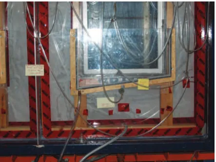
Figure 1-1: (a) schematic of front elevation of 2.44-m by 2.44-m specimen showing location of 600 mm by 1200 mm windows and adjacent wood framing studs. Detail “A” might be representative of installation details used in current practice whereas detail “V” a variation on that practice; (b) photo of the completed specimen clad with hardboard siding. ... 1-4 Figure 2-1: Typical layout of the wall specimen for comparative investigation of the water management
response of two side-by-side wall-window interface details (left). Elevation view of the exterior cladding of the specimen completed (right). ... 2-3 Figure 2-2: Front elevation of 2.44-m by 2.44-m specimen (cladding exterior) showing location of 90-mm
deficiencies (missing sealant, backer rod at specimen face) ... 2-5 Figure 2-3: Vertical wall sections facing interior (a and b) showing location (b) of water collection troughs at
(1) window on interior side of test specimen, (2) beneath window in false subsill; (3) beneath subsill for collection of water drained from subsill (see Fig. 4) and, (4) lower most trough for collection behind siding. ... 2-6 Figure 2-4: Collection trough used for the collection of water penetrating the window... 2-7 Figure 2-5: Expected direction of water drainage from subsill to collection trough (3) for variation (V-side)
and base-case (B side) portions of specimen W3 ... 2-7 Figure 2-6: Specimen W1: horizontal section showing Base Case representing “practice of interest” and
Variation on “Base Case”... 2-8 Figure 2-7: Vertical sectional views of specimen W2 at the wall-window interface showing the (a) selected
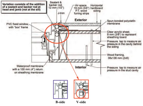
practice side (B-side; base-case) and (b) Variation (V-side) specimen configurations. ... 2-9 Figure 2-8: Schematic of horizontal section of (a) base-case (“B-side”) window and photograph (below)
showing window installed on furring strips; (b) variation (”V-side”) window and accompanying photograph (below) showing location of membrane shims on backside of mounting flange... 2-11 Figure 2-9: Specimen W4: Horizontal Section view of Wall-Window Interface at Jamb – specified practice
(B-side, Base-case) and Variation on this practice, V-side Configuration ... 2-12
Figure 3-1: A sample of hourly Driving Rain Wind Pressures for several typical Canadian locations for various return periods at the 1.8 mm/hr rain intensity threshold... 3-6 Figure 3-2: A sample of spray rates based on hourly driving rain averages for several typical Canadian
locations for various return periods. ... 3-8 Figure 3-3: A sample of Driving Rain Wind Pressures averaged over 5 minutes for several typical
Canadian locations for various return periods at the 1.8-mm/hr rain intensity threshold... 3-9 Figure 3- 4: A sample of spray rates based on driving rain with a 5-minute averaging time for several
typical Canadian locations for various return periods.. ... 3-10 Figure 3- 5: Inside view of apparatus showing a test specimen (sizes up to 2.44 by 2.44-m)... 3-14 Figure 3- 6: Schematic of apparatus and 2.44 by 2.44-m test specimen ... 3-15 Figure 3- 7: Bank of seven calibrated water collection vessels; level sensor is shown on right of photo... 3-16 Figure 3- 8: Location of pressure taps on both halves of specimen. The pressure tap designation
includes the specimen number (n) and respective tap locations... 3-16 Figure 4-1: Horizontal sectional views of Specimen W1 showing the wall-window interface at the jamb for
the Variation (V-side) and selected practice (B-side; base-case) specimen configurations. The difference between the B- and V-sides is that the B-side has a single joint seal whereas the V-side includes an additional sealant and backer rod at the interface at the head and jamb (not sill) of the window. ... 4-3 Figure 4-2: Vertical sectional views of specimen W1 at the wall-window interface showing the Variation
(V-side) specimen configurations. ... 4-4 Figure 4-3: (a) Schematic of front elevation of 2.44-m by 2.44-m specimen (cladding exterior) showing
nominal location of 90-mm deficiencies (missing sealant, backer rod at specimen face);
(b) picture of 90-mm slit located above window of Specimen W2. ... 4-5 Figure 4-4: Pressure tap locations within wall section... 4-7
List of Figures
Figure 4-5: (a) Location of pressure taps along height of half-specimen and designated tap labels;
(b) location of collection troughs 1 and 2 of half-specimen... 4-7 Figure 4-6: Expected direction of water drainage from subsill to collection Trough (2) for variation (V-side)
and base-case (B side) portions of specimen W1 ... 4-8 Figure 4-7: Specimen W1 – as built: Collection at Trough 1, 03 ABS... 4-10 Figure 4-8: Specimen W1 – as built: Collection at Trough 2, 03 ABS... 4-12 Figure 4-9: Specimen W1 – as built: Collection at Trough 2, 08 ABS... 4-12 Figure 4-10: Specimen W1 – Trial 2: Collection at Trough 2, 03 ABS... 4-13 Figure 4-11: Specimen W1 – Trial 2: Collection at Trough 2, 08 ABS... 4-14 Figure 4-12: Water Entry to Vertical and Horizontal Deficiencies (elevation view) ... 4-16 Figure 4-13: Possible path of water entry and collection to trough 2 during Trial... 4-17 Figure 5-1: Horizontal sectional views of Specimen W2 showing wall-window interface at jamb for
selected practice (B-side; base-case) and Variation (V-side) specimen configurations respectively. The difference between the B- and V-sides is that for the B-side, a self-adhered waterproof membrane (150-mm) has been placed over the window-mounting flange at jambs and head of window. ... 5-3 Figure 5-2: Vertical sectional views of specimen W2 at the wall-window interface showing the (a) selected
practice side (B-side; base-case) and (b) Variation (V-side) specimen configurations. ... 5-4 Figure 5-3: (a) Schematic of front elevation of 2.44-m by 2.44-m specimen (cladding exterior) showing
nominal location of 90-mm deficiencies (missing sealant, backer rod at specimen face); (b) picture of 90-mm slit located (deficiency 1) above window of Specimen W2 – icon relates to description (Trial 3). ... 5-5 Figure 5-4: Location of deficiency (3) in Trial 1 as shown in Figure 3... 5-7 Figure 5-5: Location of deficiency (2) in Trial 2 as shown in Figure 4... 5-7 Figure 5-6: Pressure tap locations within wall section... 5-8 Figure 5-7: (a) Location of pressure taps along height of half-specimen and designated tap labels;
(b) location of collection troughs 1 to 2 of half-specimen. Both sides had troughs located
as in (b)... 5-8 Figure 5-8: Expected direction of water drainage from subsill to collection Trough (2) for variation (V-side)
and base-case (B side) portions of specimen W2; Note that although the cladding system is considered a concealed barrier for which cladding is typically in contact with sheathing membrane, schematic is not drawn as such. This permits showing drainage of water from sill to collection Trough 2... 5-9 Figure 5-9: Water entry test Trial 2 of Specimen W2 at 03 ABS leakage, showing water collection in
Trough 2 as function of pressure differential (Pa), for B- and V-sides at different water
cascade rates... 5-14 Figure 5-10: Water entry test Trial 2 of Specimen W2 at 08 ABS leakage, showing water collection in
Trough 2 as function of pressure differential (Pa), for B- and V-sides at different water
cascade rates... 5-14 Figure 5-11: Water entry test trial 3 of Specimen W2 at 03 ABS leakage, showing water collection in
Trough 2 as function of pressure differential (Pa), for B- and V-sides at different water
cascade rates... 5-15 Figure 5-12: Water entry test trial 3 of Specimen W2 at 08 ABS leakage, showing water collection in
Trough 2 as function of pressure differential (Pa), for B- and V-sides at different water
cascade rates... 5-15 Figure 5-13: Test Trial 2 – Potential Paths of Water collection to Trough 2 for ... 5-17 Figure 5-14: Potential path of water to reservoir collection tray during test Trial 3 ... 5-18 Figure 6-1: Horizontal Sectional views of Specimen W3 showing wall-window interface at jamb for
List of Figures
Figure 6-2: Schematic of horizontal section of (a) base-case (“B-side”) window and photograph (below) showing window installed on furring strips; (b) variation (”V-side”) window and accompanying photograph (below) showing location of membrane shims on backside of mounting flange. ... 6-4 Figure 6-3: Vertical Sectional views of specimen W3 at the wall-window interface showing the (a) selected
practice side (B-side; base-case) and (b) Variation (V-side) specimen configurations. ... 6-5 Figure 6-4: (a) Schematic of front elevation of 2.44-m by 2.44-m specimen (cladding exterior) showing
nominal location of 90-mm deficiencies (missing sealant, backer rod at specimen face); (b) picture of 90-mm slit located above window of Specimen W3 – icon relates to test trial
description... 6-6 Figure 6-5: Pressure tap locations within wall section... 6-8 Figure 6-6: (a) Location of pressure taps along height of half-specimen and designated tap labels;
(b) location of collection troughs 1 to 4 of half-specimen. Both sides had troughs located as shown in (b). ... 6-8 Figure 6-7: (a) Vertical wall section showing location (b) of water collection troughs at (1) window on
interior side of specimen, (2) beneath window in false subsill; (3) beneath subsill for collection of water drained from subsill (see Fig. 6) and, (4) lower-most trough for collection
behind siding... 6-9 Figure 6-8: Expected direction of water drainage from subsill to collection trough (3) for variation
(V-side) and base-case (B side) portions of specimen W3 ... 6-10 Figure 6-9: Water collection rates to Trough 1 located at window of specimen W3 (Figure 3 (c) – trough (1));
collection rates (ml/min) are shown in relation to pressure differential (“chamber pressure”) across test specimen (Pa) for both B- and V-side of specimen at different water cascade rates for which, for example, “08 Cascade” refers to nominal cascade rate of 0.8 L/min.-m2. The test was conducted for a specimen having an ABS leakage of 0.8 L/s-m2 at 75 Pa... 6-13 Figure 6-10: Water collection rates to trough 3 located beneath sill of specimen W3; As built – 08 ABS ... 6-14 Figure 6-11: CMHC Wall 3 Reservoir Water Entry, Step 2 Deficiency, 03 ABS... 6-17 Figure 6-12: CMHC Wall 3 Reservoir Water Entry, Step 2 Deficiency, 08 ABS... 6-17 Figure 6-13: CMHC Wall 3 Reservoir Water Entry, Step 2 Deficiency with subsill collection tray, 08 ABS. 6-18 Figure 6-14: CMHC Wall 3 Subsill Water Entry, Step 2 Deficiency with subsill collection tray, 08 ABS ... 6-18 Figure 6-15: CMHC Wall 3 Pan Water Entry, Step 2 Deficiency, 03 ABS... 6-19 Figure 6-16: CMHC Wall 3 Pan Water Entry, Step 2 Deficiency, 08 ABS ... 6-19 Figure 6-17: Sectional views of W3 showing projection of window above cladding at lower exterior
corner of wall-window interface ... 6-21 Figure 6-18: Variation-side of W3 and details of deficiency at (a) lower corner of window-cladding interface;
(b) details of sill flashing showing 4-mm up-leg and; (c) water accumulation at sill flashing. ... 6-22 Figure 6-19: Vertical section at wall-window interface of (a) Variation, V-side and; (b) selected practice
B-side of W3 showing path of water entry from outside to the interior behind cladding... 6-22 Figure 6-20: CMHC Wall 3 Reservoir Water Entry, Step 3 Deficiency, 08 ABS... 6-24 Figure 7-1: Horizontal Section view of Wall-Window Interface at Jamb – specified practice (B-side,
Base-case) and Variation on this practice, V-side Configuration... 7-3 Figure 7-2: Vertical Section view of Wall-Window Interface – Best Practice and Variation Const... 7-3 Figure 7-3: Modifications at head of Specimen W4 for Repeat Tests ... 7-4 Figure 7-4: Pressure tap locations within wall section... 7-7 Figure 7-5: (a) Location of pressure taps along height of half-specimen and designated tap labels;
(b) location of collection troughs 1 to 4 of half-specimen. Both sides had troughs located
as in (b)... 7-7 Figure 7-6: (a) Vertical wall section (inter.) showing location (b) of water collection troughs at (1) window
on interior side of specimen, (2) beneath window in false subsill; (3) beneath subsill for water collection from subsill (see Fig. 6) and, (4) lower most trough for collection behind siding ... 7-8 Figure 7-7: Collection trough locations with and without sub-sill water collection to Trough 2 ... 7-9
List of Figures
Figure 7-8: Specimen W4 as built condition – Water collection in Trough 1 (window), 03 ABS... 7-12 Figure 7-9: Specimen W4 as built condition – Water collection in Trough 1 (window), 08 ABS... 7-12 Figure 7-10: Specimen W4 as built condition – Water collection in Trough 3 (window), 03 ABS... 7-13 Figure 7-11: Specimen W4 as built condition – Water collection in Trough 3 (window), 08 ABS... 7-14 Figure 7-12: Specimen W4 as built condition – Water collection in Trough 3 (window), Trough 2
(Sub-sill collection) Installed, 08 ABS... 7-14 Figure 7-13: Specimen W4 as built condition – Water collection in Trough 2 (Sub-sill), 08 ABS ... 7-15 Figure 7-14: Specimen W4 as built condition – Water collection in Trough 4 (behind cladding at base
of wall assembly), 03 ABS ... 7-16 Figure 7-15: Specimen W4 as built condition – Water collection in Trough 4 (behind cladding at base
of wall assembly), 08 ABS ... 7-16 Figure 7-16: Specimen W4 as built condition – Water collection in Trough 4 (behind cladding at base
of wall assembly), with Trough 2 (Sub-sill) Installed, 08 ABS... 7-17 Figure 7-17: Specimen W4 as built condition – Trial 2: Water collection in Trough 3 (behind cladding at
base of wall assembly), 08 ABS... 7-18 Figure 7-18: Specimen W4 as built condition – Trial 2: Water collection in Trough 4 (behind cladding at
base of wall assembly), 08 ABS... 7-18 Figure 7-19: Specimen W4 as built condition – Trial 3: Water collection in Trough 3 (apparent drainage
from sub-sill), 08 ABS... 7-19 Figure 7-20: Specimen W4 as built condition – Trial 3: Water collection in Trough 4 (behind cladding at
base of wall assembly), 08 ABS... 7-20 Figure 7-21: Specimen W4 as built condition – Trial 3: Water collection Trough 2 (subsill), 08 ABS ... 7-20 Figure 7-22: View of B-side rough head from below... 7-23 Figure 7-23: Formation of “fish mouths” around the perimeter of the B-side window... 7-23 Figure 7-24: Path of water collection at the head of the B-side window... 7-24 Figure 7-25: Specimen W4 as built condition – Trial 1 REPEAT: Water collection Trough 3 (drainage
from sub-sill), 03 ABS... 7-27 Figure 7-26: Specimen W4 as built condition – Trial 1 REPEAT: Water collection Trough 3 (drainage
from sub-sill), 08 ABS... 7-27 Figure 7-27: Specimen W4 as built condition – Trial 1 REPEAT: Water collection Trough 2 (sub-sill),
03 ABS... 7-28 Figure 7-28: Specimen W4 as built condition – Trial 1 REPEAT: Water collection Trough 2 (sub-sill),
08 ABS... 7-29 Figure 7-29: Specimen W4 as built condition – Trial 1 REPEAT: Water collection in Trough 4, 03 ABS ... 7-30 Figure 7-30: Specimen W4 as built condition – Trial 1 REPEAT: Water collection in Trough 4, 08 ABS ... 7-30 Figure 7-31: Specimen W4 – Trial 2 REPEAT: Water collection to Trough 3; 08 ABS ... 7-31 Figure 7-32: Specimen W4 – Trial 2 REPEAT: Water collection to Trough 2; 08 ABS ... 7-32 Figure 7-33: Specimen W4 – Trial 2 REPEAT: Water collection to Trough 4; 08 ABS ... 7-32 Figure 7-34: Specimen W4 – Trial 3 REPEAT: Water collection to Trough 3; 08 ABS ... 7-33 Figure 7-35: Specimen W4 – Trial 3 REPEAT: Water collection to Trough 2; 08 ABS ... 7-34 Figure 7-36: Specimen W4 – Trial 3 REPEAT: Water collection to Trough 4; 08 ABS ... 7-34 Figure 8-1: (Left) Typical layout of wall specimen framing for investigation of water management response
of two side-by-side wall-window interface details (B and V-sides). Water collection troughs are located beneath the windowsill. (Right) Elevation view of exterior cladding of specimen... 8-2 Figure 8-2: Base practice Construction W3 (Tab. 1) – Horiz. sectional view wall-window interface at jamb.... 8-6 Figure 8-3: Variation Construction W3 (Tab. 1) – Horiz. sectional view of wall-window interface at Jamb ... 8-7 Figure 8- 4: W1: Horizontal section – Best current practice ... 8-9 Figure 8-5: W1: Horizontal section – Variation on Best current practice ... 8-9
List of Figures
Figure 8-6: Difference between shingle-lapping and face-taping (Cross-sectional view of joint between
2 materials)... 8-11 Figure 8-7: Location of delamination, and in some cases, loss of cohesion between plies of the self-adhered
flashing membrane... 8-12 Figure 8-8: Locations (red arrows) along the interface between the window and sheathing board where the
flashing membrane delaminated from the sheathing membrane and formed funnels in which water accumulated ... 8-12 Figure 8-9: Water ingress at window head of specimen during a test ... 8-13
List of Tables
Table 2-1: Summary of wall-window cladding combinations selected for testing ... 2-4
Table 3-1: Key code for locations cited in Figures 1 and 3...3-6 Table 3-2: Factors to convert hourly wind speeds to shorter averaging times...3-8 Table 3-3: A proposed test protocol with notional performance levels...3-11 Table 3-4: Designation of pressure taps located in specimens ...3-16
Table 4-1: Summary of wall-window cladding combinations selected for testing - emphasis on Specimen W1 ...4-1 Table 4-2: Summary of Water Penetration or Entry Tests for Test Specimen W1 ... 4-6 Table 4-3: Stud and Cavity Pressure Drops –Test specimen in as-built condition... 4-9 Table 4-4: Water collection rates in ml/min. at trough 1 (window) for details B- and V-sides at an
ABS leakage of 0.3 l/s-m2, in relation to nominal cascade rate and pressure difference... 4-11
Table 5-1: Summary of wall-window cladding combinations selected for testing - emphasis on Specimen W2 ...5-1 Table 5-2: Summary of Water Penetration or Entry Tests for Test Specimen W2 ... 5-6 Table 5-3: Pressure drops in the stud space and cavity behind the cladding without deficiency... 5-11 Table 5-4: Summary of Results from Watertightness Performance Tests of Specimen W2 ... 5-12
Table 6-1: Summary of window-wall cladding combinations selected for testing - emphasis on Specimen W3...6-1 Table 6-2: Summary of Water Penetration or Entry Tests for Test Specimen W3 ... 6-7 Table 6-3: Stud and Cavity Pressure Drops Without Deficiency ... 6-11 Table 6-4: Water collection at troughs for tests on As-built specimen W3 (no deficiencies)... 6-12 Table 6-5: Summary of Results from Watertighness Performance Tests of Specimen W3 - Trial 2... 6-15 Table 6-6: Water collection at different troughs in relation to V- or B-side of specimen W3 for test Trial 1
(vertical opening along window jamb) and Trial 3 (vertical slit above window head) ... 6-23
Table 7-1: Summary of wall-window cladding combinations selected for testing - emphasis on Specimen W4 .. 7-1 Table 7-2: Summary of Initial Water Penetration or Entry Tests for Test Specimen W4 ... 7-5 Table 7-3: Specimen W4 - Repeated Water collection Tests... 7-6 Table 7-4: Stud and Cavity and wall-window interface Pressure Drops Without Modifications ... 7-10 Table 7-5: Stud and cavity and interface pressure drops with subsill collection trough in place ... 7-11 Table 7-6: Specimen W4 Repeat - Stud and Cavity Pressure Drops Without Modification ... 7-26
Nomenclature
ABS air barrier system
ASTM American Society for Testing and Materials
B-side base-case side of test specimen
CMHC Canada Mortgage and Housing Corporation
CSA Canadian Standards Association
DRF driving rain factor
DRWP driving rain wind pressure
DWTF dynamic wind and wall test facility
NRC National Research Council Canada
PVC polyvinyl chloride (as in PVC window)
RO rough opening (as in window rough opening)
V-side variation side of test specimen
W1 wall test specimen number 1
W2 wall test specimen number 2
W3 wall test specimen number 3
W4 wall test specimen number 4
WDR wind driven rain
Acknowledgements
The participation and support of the Wall-Window Interface joint research project partners is gratefully acknowledged and particular mention is made of contributions from the project partners including the Canada Mortgage and Housing Corporation, DuPont Weatherization Systems, and Building Diagnostics Technologies.
The authors would also like to thank the following persons for their input to the selection of the most common features of wall-window interface details:
Mr. John Vlooswyk, Building Envelope Engineering, Calgary, Alberta Mr. David Ricketts, RDH Consultants, Vancouver, British Colombia Mr. Armand Patenaude, Air-Ins, Quebec
Mr. Don Buchan, BLP Ltd., Ottawa, Ontario Mr. Jean Coté, CMHC inspector, New Brunswick
Mr. Vic Rowe, Atlantic New Home Warranty Program, Newfoundland Mr. Tom Johnston, Atlantic New Home Warranty Program, Nova Scotia Mr. Hector Doiron, inspector, New Atlantic Home Warranty
Preface
This report has been compiled based on experimental work carried out in the laboratories of the Institute for Research in Construction, a review of pertinent literature and feedback obtained from different experts and practitioners of window installation. It forms the initial part (Phase 1) of a series of three reports prepared on the “Performance Evaluation of Wall-Window Interface Details”. Of the eight chapters provided in this report, the first three provide an introduction to the work in which the approach to the performance assessment process is described, the development and rationale for the test method are given, and a summary description of the test specimens is offered. The four subsequent chapters focus on detailed results obtained from the experimental work of testing four different pairs of wall-window interface details, and the final chapter offers an overview of some of the practical considerations derived from this work. Although a brief description of the interface details and specimen configuration are provided within each Chapter, considerably more detail is given for each of the four specimen pairs in the Appendix in which the installation process is illustrated in a series of photographs. Finally, the hardcopy report also includes a softcopy of the work presented on a CD. In this CD, in addition to all of the
information provided in this report, other contributions are included that directly relate to the work carried out in this study that were either previously published in conferences, or are presentations that were made at different meetings, symposia or workshops.
Executive Summary
Inadequate detailing practice and defective installation of windows have accounted for a significant number of premature failures of the building envelope. This has spurred the development of alternative construction details to manage water intrusion at the wall-window interface. However, it is not known how effective these construction details may be over the life expectancy of the wall assembly. Laboratory investigations focused on assessing the effectiveness of wall-window interface details to manage rainwater intrusion in the wall assembly have provided an effective way to obtain useful information on the varying performance of different interface details. Previous studies undertaken to investigate the effectiveness of details typically used in wood frame low-rise wall assemblies have shown the degree to which different details manage rainwater intrusion and the extent of fault tolerance of these systems. The current study was undertaken to investigate the effectiveness of such details, typically used in wood frame low-rise wall assemblies, to manage rainwater.
This report provides results obtained from evaluating the watertightness of a series of four wall-window interface details representative of construction practice across Canada. An overview of the experimental approach is provided and includes the development of the test protocol, a description of the test apparatus and the basis for estimating the effects on specimens subjected to simulated climate loads. The test specimen configuration is described and details of four sets of wall-window interfaces and variations on their implementation are provided. The results of water penetration tests are presented in terms of water entry through deficiencies in the cladding, water collection within the assembly and the severity of the simulated wind-driven rain loads. Results on water entry for the different wall-window interface configurations are given and the
Cha pt e r 1 — I nt roduc t ion
Background Information
A key design element for exterior walls is the control of rain penetration. Lack of attention to design principles or failure to implement them in the detailing of wall components may lead to premature deterioration of wall elements. Inadequate detailing and defective installation of windows has accounted for a significant number of premature failures of the building envelope as has been evident across Canada in past years [1, 2, 3, 4]. For example, a survey of building envelope failures in the coastal region of British Columbia indicated that 25% of the moisture problems associated with water ingress into wall assemblies were directly attributed to penetration through the windows or the window-wall interface [3]. However, the issue of building envelope failure is not one that is limited to coastal climates, although it is likely that assemblies are more vulnerable in such climates, but one that has found interest throughout North America and abroad in regions where wood frame housing is also in use such as New Zealand.
For example, the Building Research Association of New Zealand undertook research studies [5] into the weathertightness performance of the installation of windows in cladding for low-rise residential construction in New Zealand, focusing on assessing the performance limitations in weathertightness of the Window Association of New Zealand’s Window Installation System for direct-fixed cladding in low-rise residential construction.
More recently, the issue of premature failure of the building envelope has been apparent in Minnesota [6], where it is reported by the building inspection division of the town of Woodbury that homes built since 1990 were experiencing major durability problems. Specifically, 276 of 670 stucco homes built in Woodbury in 1999 have failed (ca. 41%); the primary cause for failure were window leaks, lack of kickout flashing, and improper deck flashing above the wood framing [6]. Clearly the problem of water penetration at window openings persists and not only in coastal areas for which the perception is that climate loads are very severe. Although coastal climates may be severe, details that promote the entrapment of water and are not fault tolerant are likewise susceptible to premature deterioration, even in areas of apparently reduced “climate loads”.The state of California has taken interest in understanding the level of risk afforded by different window installation methods and has recently reported on a test program to evaluate the performance of different window installation details [7]. The overall goal was to perform a systematic laboratory evaluation of specifically identified conventional and innovative residential building materials, assemblies, and construction practices. The laboratory evaluations were
designed to provide experimental evidence of moisture loading, propensity for mold formation, and potential performance improvements associated with innovative building assemblies and construction practices.
In North America, this more recent interest has spurred a review of existing standards of the American Society for Testing and Materials (ASTM) [8] and in the Canadian context, standards of the Canadian Standards Association (CSA) for assessing the performance of windows [9]. Two studies focused on assessing the watertightness of windows and the wall-window interface were completed by Ricketts [10, 11] on behalf of Canada Mortgage and Housing Corporation (CMHC). Results indicated that although a wide range of causal factors was found to contribute to leakage activity, the principal paths for water leakage are those associated with the wall-window interface. These could occur either through the window assembly to the adjacent wall assembly or through the window to wall interface with the adjacent wall assembly. A review of the CSA A440 B rating performance [9] indicated that the criteria for water penetration control do not identify leakage associated with these leakage paths, nor is there a requirement for testing of the installed window assembly. Additionally, it was found that the selection of windows and the design of the wall-window interface do not consider local exposure conditions as may be provided by the local topography or other building features such as overhang protection.
Some recommendations that followed from these reports included [10 and 11]: • Assessment of in-service and micro-exposure (at window proximity) conditions • Provision for redundancy in water penetration control through the installation of sub-sill
drainage.
• Consideration of the durability of water penetration control performance
• Development of a water penetration testing protocol for the window to wall interface Given the nature of these recommendations there was a need to obtain useful benchmarking information on the effectiveness of different construction details at managing water intrusion over the life expectancy of the wall assembly. Such information would necessarily benefit building envelope designers, specifiers and expert practitioners. As well, considering that the deterioration of building materials within exterior walls can progress significantly before any symptoms become apparent to the owner, one should not rely solely on feedback from in-situ investigations to assess the effectiveness of the window-wall interface details. Laboratory investigations can provide an effective way to obtain reliable, insightful information regarding the effectiveness of specific wall-window interface details to manage rainwater intrusion in the wall assembly [12, 13]. Although laboratory studies are short–term tests that do not directly relate to expected long-term performance, these can be used to determine the response of wall assemblies to specific rain events in a given climatic region for which the recurrence period can be ascertained. Establishing the response of wall assemblies to simulated events for which the period of reoccurrence is known is an indirect means of determining the likely risk of water entry over a given period and for a specific region. These may also provide some measure of the expected risk to water entry and the fault tolerance of different installations methods in extreme conditions.
Hence there is widespread interest in obtaining a better understanding of the comportment of different window installation methods for a range of climate loads. Accordingly, a study was undertaken to investigate the ability of such details, typically used in wood frame low-rise wall assemblies, to manage rainwater the approach and outline of which is provided in the subsequent section.
Experimental Approach To Evaluating Water Management of Window
Interface Details and Report Outline
The current test program, which is described below, has sought to evaluate different wall-window interface details and their ability to manage rainwater entry and as well, provide a means of assessing the robustness of specified design by, for example, considering what occurs when jointing products fail or construction has reduced airtightness. In addition, a test program having a specified test protocol nominally permitsbenchmarking “performance” of proposed interface design details. As well, the development of a “standards” approach in a laboratory setting offers potential as a precursor to a field certification protocol that is currently lacking.
What follows is a brief outline of the report that also provides a synopsis of the experimental program including the basic objective, development of the specimen configuration and test protocol. Information is given on the nature of results and practical considerations derived from them as well as a summary of the contents of the respective Appendices.
Objective
The objective of the experimental work was to compare the ability of different wall-window details to manage rainwater. Given the many different combinations of windows, wall cladding systems and related interface details that could be assessed, importance was placed on establishing specifications to which all test specimens would nominally be fabricated, including:
• Overall size of specimen (determined by maximum size permissible in test apparatus) • Size and location of windows
• Type of windows and cladding
• Type of sheathing board, sheathing membrane and interior finish
Development of Test Specimen Configuration
Accordingly, the configuration of test specimens was established that nominally permitted
comparisons among the different details when subjected to simulated wind-driven rain conditions. Wall specimens were designed to permit side-by-side comparison of two wall-window interface details (Figure 1-1). Hence, each 2440 mm by 2440 mm wall specimen included two half-specimens, each with large openings of 635-mm by 1245-mm, and in each of which was placed a 610 mm by 1220 mm window together with a set of wall-window interface details. These details include those located at the head, the jambs and the sill. One half of the specimen included a “selected practice detail”, the other a “variation”, which typically could be an “upgrade” of the interface detail that may or may not be common but nonetheless presented a research interest. Entry of water around either window opening was collected in troughs located beneath the
respective sills. Water was also collected at the window, just beneath the sill level, on the interior side of the specimen. Thereafter, a choice was made as to which wall-window combinations to evaluate based on regional considerations of current practice and variations thereof. A summary regarding the test specimen configuration specific to the results reported are provided in Chapter 2 (Summary description of test walls) and further details are provided in the Appendix A (Detailed Description of Walls).
Development of Test Protocol and Use of the Dynamic Wind and Wall Test Facility (DWTF)
The (DWTF), previously used to subject similar specimens to simulated wind-driven rain conditions, has been shown to offer a reproducible method for subjecting specimens to simulated wind-driven rain [14]. A test protocol was developed based on previous work [14], and also took into consideration existing North American water penetration test standards such as ASTM E331 [8] and CSA A440 [15]. The protocol established parameters for spray rate (water deposition rate) on the cladding and pressure difference across the assembly [12]. Specimens were thus subjected to simulated wind-driven rain conditions for specified periods of time; these conditions replicated the main features of rain events. Rates of water entry at the subsill and behind the cladding were determined by measuring the rate of water collected from these locations as well as that portion that entered the window at the interface between the window lite and frame. The use of the facility together with the test protocol permitted comparisons of water entry results among the different wall-window interface details. Both the apparatus and protocol are described in Chapter 3 (Performance Assessment of the Wall-Window interface).
Figure 1-1: (a) schematic of front elevation of 2.44-m by 2.44-m specimen showing location of windows and wood framing studs. Detail “A” might be representative of installation details used in current practice whereas detail “V” a variation on that practice; (b) photo of completed specimen clad with hardboard siding.
Results From Watertighness Testing of Four Sets of Wall Assemblies
Chapters 4 to 7 provide the results of watertightness tests of four sets of wall-window interface details (W1 to W4) configured for:
• Fixed or combination PVC window units,
635-mm (25 in.) 2440-mm (96 in.) 1220-mm (48 in.) 12 55 -mm (4 9-½ in. ) 244 0-mm (96 in. ) 17 50 -mm (6 8-⅞ in. ) 17 5-mm (6 -⅞ in. ) 514-mm (2 0-¼ in. )
(a)
(b)
• With and without mounting flanges, and
• Installed in a rainscreen or direct applied wall assembly.
Interface details of the various approaches to window installation are given and the effectiveness of different details in managing rainwater entry is discussed in terms of the degree of drainage from the sill, the amount of water present behind the cladding, and the capacity of the installation system as a whole to manage rainwater entry. Drainage was estimated from the collection of water in purposely built troughs from which water collection rates were measured in relation to simulated wind-driven rain conditions and other test parameters affecting the degree of entry at the interface including the degree of air leakage across the test assembly and the incorporation of deficiencies in the cladding, window, and air barrier system.
Practical Considerations
Chapter 8 offers a summary of the practical considerations derived from testing the four (4) wall sets as these relate to: (1) the design and selection of components for the wall-window interface, and; (2) installation. Practical concerns that relate to design and design decisions, may, for example, take into account the selection of window details in relation to climate loads, the choice of flanged or box windows, the significance of flat sills or sills that incorporate slopes. Other considerations in respect to the selection of material may include the importance of jointing products; self adhered flashing membranes and the use of tape to help seal the interface from water entry and air leakage. These items are discussed in the context of how the choice of product may affect water management at the wall-window interface as based on the results obtained in the experimental study. Regarding installation practice, emphasis is placed on demonstrating the importance of proper and adequate care of installation of components as these necessarily relate to offering the respective installation details an adequate degree of robustness. Whether the
discussion focuses on the design and selection of components or installation practice, reference is made to the experimental results that sustain the findings derived in this study.
Appendices
The report includes a number of appendices of which one is included in this report and the broader list is included in the accompanying CD as these were quite numerous and more easily accessible in electronic format.
Included in this report is “Appendix A – Detailed Description of the Wall Specimens”, in which is given both horizontal and sectional views of the various wall assemblies and as well, offers details in respect to the sequence of installation of individual components.
In the electronic version of this report two additional appendices are included, specifically: • Appendix B, copies of papers or articles published in recent conferences are provided and
cover information on selected results from tests or draw upon key findings of the work as described in this report.
• Appendix C – Presentations, in which copies of presentations are provided that were made reporting on selected results.
References
1. Scott, D.L. (1984), “Rain Leakage in Wood Frame Walls: Two Case Histories”, Building Research Note No. 210, National Research Council of Canada.
2. Blackall, T.N. and Baker, M.C. (1984), “Rain Leakage of Residential Windows in the Lower Mainland of British Columbia”, Building Practice Note, Division of Building Research, National Research Council of Canada, BPN-42, pp. 8, November.
3. Morrison Hershfield Limited (1996), “Survey of Building Envelope Failures in the Coastal Climate of British Columbia”, Canada Mortgage and Housing Corporation, 43 p. 4. Building Envelope Engineering (1999), “Wall Moisture Problems in Alberta Dwellings”,
Canada Mortgage and Housing Corporation, 60 p.
5. Burgess, J. (2002), WANZ WIS Parameter Investigation. Report 1 – Direct Fixed Cladding, Report Number EC0610, BRANZ Limited, Porirua City, New Zealand, 15 p.
6. Anon (2005), “Stucco in Residential Construction”, City of Woodbury (MN), Building Inspection Division, Update, February 9, 2005.
7. Neil Leslie (2006), Window Installation Methods Test Results, Task 3.3 Report (California Energy Commission / Contract No. 500-03-013), GTI Project No. 15485, Gas
Technology Institute, Des Plaines, IL, 38 p.
8. E331-00 (2005), Standard Test Method for Water Penetration of Exterior Windows, Skylights, Doors, and Curtain Walls by Uniform Static Air Pressure Difference, ASTM International, West Conshohocken, PA, USA, 4 p.
9. CAN/CSA A440 (2000), Windows, Canadian Standards Association, Mississauga, ON, 249 p.
10. Ricketts, D. R. (2002), “Water Penetration Resistance of Windows: Study of Manufacturing, Building Design, Installation and Maintenance Factors”, Study 1, Canada Mortgage and Housing Corporation, Ottawa, December, 86 p.
11. Ricketts, D. R. (2002), “Water Penetration Resistance of Windows: Study of Codes, Standards, Testing and Certification”, Study 2, Canada Mortgage and Housing Corporation, Ottawa, December, 91 p.
12. Lacasse, M. A., O’Connor, T. J., Nunes, S. and Beaulieu, P. (2003), “Report from Task 6 of MEWS Project Experimental Assessment of Water Penetration and Entry into Wood-Frame Wall Specimens, Final Report”, Research Report 133, Institute for Research in Construction, National Research Council Canada, 133 p., February (IRC-RR-133). 13. Lacasse, M. A. (2003), “Durability and Performance of Building Envelopes,” BSI 2003 Proceedings (15 Cities across Canada, 10/7/2003), pp. 1-6, October (NRCC-46888) 14. M. A. Lacasse, M. Rousseau, S. M. Cornick and S. Plescia (2005), Assessing the
Effectiveness of Wall-Window Interface Details to Manage Rainwater, 10th Canadian Conference on Building Science & Technology, Ottawa, ON, May 12-13, pp. 127-138; (NRCC-47685).
15. CAN/CSA A440.4 (1998), Window and Door Installation, Canadian Standards Association, Mississauga, ON
Cha pt e r 2 —
Sum m a ry De sc ript ion of T e st
Spe c im e ns
Introduction
The following section provides a summary description of the test specimens in which some background information on regional construction practice for low-rise wood-frame homes in Canada is outlined, as is window usage and installation practice across Canada. The rationale for the selection of different details is provided, as are the nominal assembly details for each of the four test specimens. Additionally, information is given on test variations, modifications made to the assemblies that include deficiencies through which water was introduced, and methods for incorporating troughs in the assemblies for the collection of water.
A more detailed description of the respective full-scale test specimens is provided in the Appendix (Detailed Description of Walls), in which horizontal and vertical cross sectional views are given as well as photographs taken during their fabrication that illustrate the installation of individual components of the assembly.
The intent of this section, apart from offering the rationale for the selection of the components and detailed assembly of the specimens, is to provide some measure of understanding of the different variations and the manner in which these are assessed through the use of modifications to the cladding or interior finish as well as the approach adopted to collect water and retrieve information insightful to assessing their respective performance in managing rainwater entry.
Review of Wall-Window Detailing
A team of Canadian building envelope specialists provided input into what is currently best practice and typical practices of detailing the wall-window interface of wood-frame residential buildings in their respective geographical region of practice. Commercial, institutional and industrial window installation practices were not considered. Specific, though not exhaustive, information was obtained on regional practice of the West Coast, the Prairies (i.e. Alberta, Saskatchewan, Manitoba), Quebec and Atlantic Canada. This exercise highlighted significant differences in regional practices across Canada for detailing the wall-window interface and wall assembly that are given below. These differences can be related to climate severity as well as traditional practice.
• On the West Coast PVC flanged windows are predominantly used and the cladding (particularly traditional stucco) tends to be installed over a 10 to 19-mm cavity created by the installation of vertical furring strips. Best practices include installing a water-resistant membrane over the rough framing of the opening (i.e. rough opening) and a waterproof membrane on the subsill*, which is intended to drain into the cavity behind the cladding. Thermal insulation is usually not placed in the 12-15 mm (1/2 to 5/8 in.) void between the window frame and the rough opening.
• In the Prairies, PVC flanged windows are also predominantly used and the cladding is typically installed directly against the backup wall. Typically no attempt is made to drain the subsill or protect the rough opening materials against water absorption. Best current practice includes the addition of water-resistant membranes over the materials of the rough opening. • In Quebec, box frame (non-flanged) windows are common and the trend is to install the
cladding over a cavity. The gap between the window frame and the rough opening is usually filled with thermal insulation. Best current practice includes the installation of a water-resistant membrane on the material making up the rough opening and a waterproof
membrane on the subsill. The subsill is intended to drain into the cavity behind the cladding. • In the Atlantic Provinces, vinyl siding is the most common type of exterior cladding and is
usually applied directly over the sheathing membrane (water resistive barrier). The use of PVC flanged windows is typical. The most commonly used sheathing membrane is polymer based. At the wall-window interface, it is customary to use construction tape to seal the sheathing membrane to the window flange at its perimeter when the window is installed before the sheathing membrane. Another practice is to place strips of sheathing membrane over the sheathing board at the sill and jambs before then installing the window. Another practice is to fold the sheathing membrane inside the rough opening prior to installing the window. Insulation fills the gap between the rough opening and the window frame; either spray-in-place polyurethane foam is used or batt insulation. The incorporation of a drip cap flashing at the window head is not a common practice.
• In Ontario, PVC flanged windows are commonly used. The siding is usually directly installed onto the sheathing membrane (water resistive barrier). Spray-in-place polyurethane foam is predominantly used to fill the gap between the rough opening and the window frame in retrofit applications; variations on the joint between the sheathing membrane and window frame are similar to the range of variations of the Atlantic Provinces.
Following a review of the information obtained from the regional experts and a review of manuals, standard guides and research studies related to window installation [1, 2, 3, 4, 5, 6, 7, 8, 9, and 10], the selection of wall-window interface details was based on:
• Current industry issues related to water management at wall-window interfaces, including: o Shielding the window junctions from rainwater loads using end dams at both
extremities of the window head flashing,
*
Reference is made throughout the text to the terms: rough opening, subsill and windowsill. Refer to the Appendix A for definitions used in this report pertaining to these terms.
o Allowing redundancies in the assembly for the collection and evacuation of water that may get beyond the first line of defense (i.e. cladding),
o Designing the details based on the assumption that the window frame was not completely watertight and would leak sooner or later, thus allowing water inside the wall assembly.
• Representation of best as well as typical regional Canadian practices. Practices varied by region and the project aimed at providing information on the comparative performance of a diverse array of practices.
Common Features of Wall Specimens Subjected to Tests
The primary features of the test specimen, as shown in Figure 2-1, were in part determined from the need to accommodate a 2.44-m by 2.44-m test frame that fits to the DWTF test apparatus. Given one of the objectives of the experimental work was to compare the ability of different wall-window interface details to manage rainwater entry, the wall specimens were designed to allow side-by-side comparison of two wall-window interface details. Each 2.44-m (8 ft) by 2.44-m (8 ft) wall
specimen included two large openings, each of which accommodated a window together with a set of wall-window interface details for the head, the jambs and the sill. Hence, the size of windows (610 mm wide by 1220 mm high) permitted accommodating two sets of wall-window installation details in the wall specimen. As well, a window height of 1220 mm allowed for about 610 mm of opaque wall above the window, thereby permitting water to run off over the window head. Using this configuration, half of the specimen included a wall-window interface detail that was a “practice of interest” or “base case” technical solution (B-side) whereas the other half a variation (V-side) on the interface details that may or may not have been common but nonetheless presented a research interest. Throughout the report, mention is made of B-side and V-side details as described above. Both horizontal and vertical details for each of these are provided when reporting on the results from performance tests on the respective wall assemblies.
Figure 2-1: Typical layout of the wall specimen for comparative investigation of the water management response of two side-by-side wall-window interface details (left). Elevation view of the exterior cladding of the specimen completed (right).
635-mm (25 in.) 2440-mm (96 in.) 1220-mm (48 in.) 125 5-mm (49 -½ in.) 244 0-mm (96 in.) 175 0-mm (68 -⅞ in.) 175 -mm (6 -⅞ 514 -mm (2 0-¼
The configuration of the walls was intended to be representative of low-rise residential
construction with the exception of changes for clear sheathing materials. As such, the specimen consisted of: 38 by 138-mm (nominal 2-in. by 6-in.) wood studs, transparent acrylic sheet on the inside as the designated element of the air barrier system (ABS), two acrylic sheets installed with a 3-mm gap at mid-height of the specimen on the exterior of the wood frame acting as the sheathing board, spun-bonded polyolefin membrane or asphalt impregnated paper serving as sheathing membrane and an exterior horizontal hardboard siding installed on vertical furring strips for one set of test runs and directly against the back-up wall for a second set. Clear acrylic sheets were used instead of common building materials given that their transparency provided a means to trace water entry from behind the sheathing board. The expectation was that the location and timing of water ingress could readily be observed using this technique.
Summary Of Wall-Window Interface Variations Tested
In respect to the windows, these were selected on the basis of regional variations regarding window-framing features that might affect the detailing of the wall-window interface for water management. Various types of PVC windows were used in the project and included:
• Non-finned (“box”) window frame, fabricated in Canada; • Fixing flange integral to the frame, fabricated in Canada.
As well, both fixed and operable sliding windows were used and where operable windows were utilized, these formed the upper part of a combination operable-fixed window.
A summary of the different wall-window combinations including information on window frame and type, wall and siding types and variations of interface details is provided in Table 2-1
Table 2-1: Summary of wall-window cladding combinations selected for testing Speci
-men
Window
Frame Window Type*
Wall Type / Siding Installation
Variation (determine effect of)
W1 Box
(Non-flanged) Fixed
Rainscreen wall – clear cavity behind siding
Extra seal at junction of jambs and head of window R.O.**
W2 Fixed Concealed barrier wall
– no clear cavity
Changes in protection of R.O.; back dam at subsill
W3 Rainscreen wall – clear
cavity behind siding
Two subsill drainage methods for flat sill
W4
Flanged Combination - Operable sliding
(upper) / Fixed
(lower) Concealed barrier wall – no clear cavity Sealing sheathing membrane to window flange
Deficiencies Incorporated in the Cladding
As shown in Figure 2-2, three (3) sets of deficiencies were incorporated at the interface between the exterior cladding and the window frame and included: (1) 90-mm vertical slit (ca. 2-mm width) above window heads; (2) 90-mm missing length of sealant and backer rod located at the horizontal joint along the lower and outer corner of the window frame, at the junction of the window frame and the sill flashing, and; (3) a 90-mm long by 6-mm wide missing sealant and backer rod in a vertical joint at mid-height of the outer window jamb. Each of these locations is identified in Figure 2-2.
Figure 2-2: Front elevation of 2.44-m by 2.44-m specimen (cladding exterior) showing location of 90-mm deficiencies (missing sealant, backer rod at specimen face)
90-mm deficiency 90-mm vertical slit
1
2
3
Water Collection Troughs
Water penetration at the window proper, entering unintended openings in the cladding and interface, or entering through deficiencies, was collected in troughs located at the base of the wall and beneath the window subsill as shown in Figure 2-3 (a). The use of troughs as shown in Figure 2-3 (b), evolved from an initial set of two troughs used in specimen W1 and W2, ultimately to the use of four troughs as depicted in the figure.
Figure 2-3: Vertical wall sections facing interior (a and b) showing location (b) of water collection troughs at (1) window on interior side of test specimen, (2) beneath window in false subsill; (3) beneath subsill for collection of water drained from subsill (see Fig. 4) and, (4) lower most trough for collection behind siding.
A trough located at (1) in Figure 2-3 (b) was intended for the collection water that would penetrate the window between the lite and window frame; a picture of such a trough affixed to the back of the specimen, is shown in Figure 2-4. Such a trough, or variations thereof, was used for all four wall specimens.
Water accumulating at the subsill could be collected in a removable trough at (2); this trough was used for subsill collection in specimens W3 and W4. A trough located beneath the subsill at (3) was intended for measuring water drainage from the subsill to the trough; this trough was present for all specimens. Water finding its way behind the cladding would be collected near the base of the wall in the trough at (4); this trough was used in specimens W3 and W4.
a b
1
3
4
2
Figure 2-4: Collection trough used for the collection of water penetrating the window
The use of all four troughs nominally permitted quantifying the amount and rate of water entry along different paths and differentiating the significance of these paths given different test conditions.
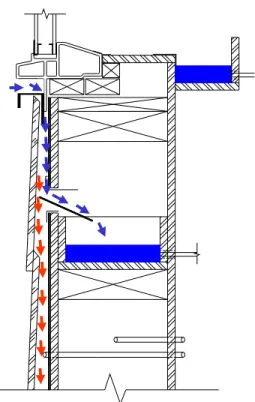
For example in assembly W3, water entering the subsill area, as shown in Figure 2-5, would drain from the subsill down the front of the waterproof membrane and be directed into collection trough (3) beneath the subsill. As shown in the figure, water was redirected to this trough using a protruding metal plate that was placed in a horizontal opening, a narrow slit, located ca. 180-mm below the sill edge.
Figure 2-5: Expected direction of water drainage from subsill to collection trough (3) for variation (V-side) and base-case (B side) portions of specimen W3
A description of the method used to determine water collection rates for the respective troughs is given in Chapter 3 (see § Calibrated water collection vessels).
Wall-Window Detailing for W1
The effect of certain design features on the water management at the wall-window interface was investigated and included:
• Levels of drainage in place at the subsill of the rough opening (for box and flanged window frame installations);
• Levels of redundancy in the seals installed at the wall-window interface (for box frame window installation).
The reference assembly, representative of the Quebec region, is a pair of box frame windows installed in a wall with a clear drained cavity of 19 mm depth behind the cladding. Figure 2-6 provides the wall-window details for the “Base Case” half of the test specimen and the “Variation” half of the test specimen (Side “V”). The difference between the two details is an additional seal joining the window frame to the sheathing board, at the jambs and head of the rough opening for the “Variation” half of the test specimen. This creates an additional level of redundancy in the event that the external seal becomes deficient during its service life.
V-side B-side
Figure 2-6: Specimen W1: horizontal section showing Base Case representing “practice of interest” and Variation on “Base Case”.
Wall-Window Detailing for Specimen W2
These installation details focused on the installation of windows that included integral mounting flanges when installed in a non-rainscreen concealed barrier wall. In particular, there was interest in gaining some perspective on two different approaches to the protection of the wood-based components at the rough opening and whether a back dam at the subsill would provide an additional degree of protection against water entry.
Of the two different installation methods, the specified practice (“base-case”; “B-side”) of Specimen W2 (Figure 2-7) included a back dam at the interior face of the rough flat sill, the sill being overlaid with a self-adhered bituminous-based waterproofing membrane, that was lapped over the sheathing membrane, as well as a self-adhered waterproofing membrane to seal the sheathing board to the window flange at the jambs and head. The flat sill on the V-side was not protected and the sheathing membrane was lapped under the window flange at the rough sill, and lapped over the window flange at the jambs and head.
Figure 2-7: Vertical sectional views of specimen W2 at the wall-window interface showing the (a) selected practice side (B-side; base-case) and (b) Variation (V-side) specimen configurations.
B-side
V-side
B-side: back dam at sill, and incorporation of waterproofing membranes at head, jambs and sill of window
V-side: no back dam or use of waterproof membranes – sill unprotected
Wall-Window Detailing for Specimen W3
These installation details focused on the installation of windows that included integral mounting flanges and solutions for detailing such windows when incorporated in a rainscreen wall. The use of PVC windows having integral mounting flanges is typical in new construction practice but is increasingly being used when reconstruction of damaged facades is required. Given that for reconstruction there is also interest in applying a rainscreen wall solution, focus was placed on evaluating different variations of such installation details. The intent was to determine if, between different approaches, significant differences would be observed in respect to the water
management of the respective details. In particular, there was interest in knowing the degree to which the different approaches would permit adequate drainage of the subsill area, and as well whether the mounting flanges would restrict the rate of drainage from the subsill.
Specimen W3 included PVC combination windows† having integral mounting flanges that were installed in a rainscreen wall incorporating a 19-mm clear cavity behind the cladding. The hardboard siding was affixed to 19-mm pressure-treated furring strips, the strips fastened to 2-in. by 6-in. (38-mm by 138-mm) wood frame studs. The rough opening at the sill was protected with strips of bituminous-based self-adhered membrane: one membrane covered the rough sill, the bottom of the rough jambs, and extended 150-mm over the sheathing membrane below the subsill. A second strip of self-adhered membrane covered the bottom 150-mm of the rough jambs and a 150 mm wide band of sheathing board. A paper-based asphalt impregnated product used for the sheathing membrane, was also used to protect the remaining portions of the rough opening extending along the height of the jambs and across the head of the window.
Of the two different installation methods, the specified practice (“base-case”; “B-side”) included installation of the window flange directly on the furring strips, as shown in Figure 2-8 (a). The variation of this detail (“V-side”), shown in (b), had the window flange mounted to the protected sheathing board on the backside of which were placed shims (shown in photograph) that provided a small space (2-3-mm) between the mounting flange and the board. The shims were made of small portions of bituminous-based self-adhered membrane that had been folded over and applied to the flange at fastener locations. Following the window installation, sheathing membrane was loosely installed (no seal) over the window flange at the head and jambs (additional details regarding the sequence of installation is provided in Chapter 6 – Watertightness Tests on Specimen W3). Drip cap flashing (rigid PVC), not incorporating end-dams, was installed at window heads whereas rigid metal flashing, serving as sill drip cap, was placed at the junction of the window and cladding. The 6-mm joint between cladding and window frame was sealed with a backer rod and sealant.
†
Horizontal sliding upper portion of 800-mm height, CSA rating B3; fixed lower portion of 400-mm height, CSA rating B4; total assembly not rated
Figure 2-8: Schematic of horizontal section of (a) base-case (“B-side”) window and photograph (below) showing window installed on furring strips; (b) variation (“V-side”) window and accompanying photograph (below) showing location of membrane shims on backside of mounting flange.
Wall-Window Detailing for Specimen W4
The focus was on the installation of windows that include integral mounting flanges when incorporated in a non-rainscreen concealed barrier wall. There was particular interest in gaining some information on different approaches to the sealing of the sheathing membrane at the perimeter of the window and whether, or not, such approaches would provide adequate protection against water entry should there not be a seal applied at the window perimeter between the cladding and window frame.
In both cases the sheathing membrane was installed after the installation of the window, as is often the case in current wood frame construction practice. However on the B-side, the sheathing membrane was sealed to the window frame at its perimeter using 50-mm wide strips of self-adhered elastomeric membrane whereas on the V-side, the sheathing membrane was lapped over the window frame flange without additional measures to ensure a tight seal.
Horizontal sectional views for the B- and V-sides showing the wall-window interface at the jamb of specimen W4 are provided in Figure 2-9.
Window installed over furring strips
V -side
B-side
a
b
Figure 2-9: Specimen W4: Horizontal Section view of Wall-Window Interface at Jamb – specified practice (B-side, Base-case) and Variation on this practice, V-side Configuration
Interior
Exterior
ulate t the rface 6 mm gap between edge of siding andwindow frame
50 mm wide self-adhered waterproof flashing membrane sealing the SBPO membrane to the window-mounting flange