Publisher’s version / Version de l'éditeur:
Water Distribution Systems Analysis 2010, pp. 1146-1159, 2010-09-12
READ THESE TERMS AND CONDITIONS CAREFULLY BEFORE USING THIS WEBSITE.
https://nrc-publications.canada.ca/eng/copyright
Vous avez des questions? Nous pouvons vous aider. Pour communiquer directement avec un auteur, consultez la
première page de la revue dans laquelle son article a été publié afin de trouver ses coordonnées. Si vous n’arrivez pas à les repérer, communiquez avec nous à PublicationsArchive-ArchivesPublications@nrc-cnrc.gc.ca.
Questions? Contact the NRC Publications Archive team at
PublicationsArchive-ArchivesPublications@nrc-cnrc.gc.ca. If you wish to email the authors directly, please see the first page of the publication for their contact information.
This publication could be one of several versions: author’s original, accepted manuscript or the publisher’s version. / La version de cette publication peut être l’une des suivantes : la version prépublication de l’auteur, la version acceptée du manuscrit ou la version de l’éditeur.
For the publisher’s version, please access the DOI link below./ Pour consulter la version de l’éditeur, utilisez le lien DOI ci-dessous.
https://doi.org/10.1061/41203(425)104
Access and use of this website and the material on it are subject to the Terms and Conditions set forth at
Fatigue failure of large-diameter cast iron mains
Rajani, Balvant; Kleiner, Yehuda
https://publications-cnrc.canada.ca/fra/droits
L’accès à ce site Web et l’utilisation de son contenu sont assujettis aux conditions présentées dans le site LISEZ CES CONDITIONS ATTENTIVEMENT AVANT D’UTILISER CE SITE WEB.
NRC Publications Record / Notice d'Archives des publications de CNRC: https://nrc-publications.canada.ca/eng/view/object/?id=cb148786-ee24-455c-84aa-36a43f3b921d https://publications-cnrc.canada.ca/fra/voir/objet/?id=cb148786-ee24-455c-84aa-36a43f3b921d
Fa t igue fa ilure of la rge -dia m e t e r c a st iron m a ins
N R C C - 5 3 6 1 0
R a j a n i , B . B . ; K l e i n e r , Y .
S e p t e m b e r 2 0 1 0
A version of this document is published in / Une version de ce document se trouve dans:
Water Distribution System Analysis 2010 - WDSA2010, Tucson, AZ, USA,
September 12-15, 2010, pp. 1-13
The material in this document is covered by the provisions of the Copyright Act, by Canadian laws, policies, regulations and international agreements. Such provisions serve to identify the information source and, in specific instances, to prohibit reproduction of materials without written permission. For more information visit http://laws.justice.gc.ca/en/showtdm/cs/C-42
Les renseignements dans ce document sont protégés par la Loi sur le droit d'auteur, par les lois, les politiques et les règlements du Canada et des accords internationaux. Ces dispositions permettent d'identifier la source de l'information et, dans certains cas, d'interdire la copie de documents sans permission écrite. Pour obtenir de plus amples renseignements : http://lois.justice.gc.ca/fr/showtdm/cs/C-42
FATIGUE FAILURE OF LARGE-DIAMETER CAST IRON MAINS
Balvant Rajani and Yehuda Kleiner
National Research Council of Canada, Institute for research in Construction, 1200 Montreal Road, Ottawa, Ontario, K1J 6G8 Canada
Balvant.Rajani@nrc-cnrc.gc.ca
Abstract
Water utility engineers have reported on large diameter water main failures that occurred suddenly wi warning, no signs of prior leaks and no visual evidence of corrosion on the fracture surfaces. Often the failed mains had been operating without major problems for over 80 years. A possible explanation m attributed to alternating or fluctuating stresses such as those caused by heavy traffic and cyclical operating water pressure with occasional occurrences of transients. These fluctuating stresses are accentuated pipe impinges on an object with sharp geometry and high stiffness like a rock or a stone.
thout se ay be if the
Fatigue of cast iron has been extensively studied in the context of cast iron bridges, structural elements s be taken
A mechanistic approach to explain fatigue failures of buried cast iron pipes had not been previously ome
the d t iron
Keywords
ns, large diameter, alternating stresses, fatigue failures.
1. BACKGROUND
eers from water utilities on some cast iron main failures follow these lines: “ We
e cited above, anecdotal speculation(s) (CIPRA, 1927; Handover, such as columns, engine blocks, etc, but not in the context of buried, grey cast iron water pipes. Fatigue analysis methods developed over the years involve a lot of empiricism and combine engineering principle with experimental observations. Consequently, it is fair to say that fatigue analysis results should
more as a guide than as precise or accurate answers.
explored. This paper explores the application of the fracture mechanics approach (LEFM) to explain s failures in cast iron pipes that occur through the fatigue mechanism. It endeavors to provide insight into plausibility of fatigue failures in grey cast iron pipes when and if subjected to alternating (also often referred to as repeated or variable) stresses due to surface traffic loads, operating pressure variations an transient pressure occurrences. It is important to note that the proposed analysis refers to grey cas pipe type, with carbon in form of flake graphite, which is the predominant material of existing iron trunk mains in North America and Europe.
Cast iron mai
Anecdotes told by engin
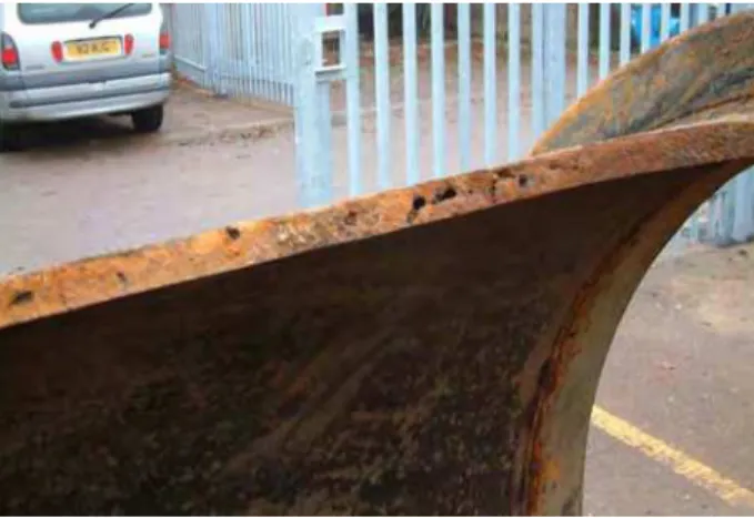
had a large diameter water main fail suddenly and visual examination of the fracture surfaces showed no signs of corrosion. There was no prior warning or a leak that surfaced to indicate that anything imminent was about to happen. This main has been operating without major problems for over 80 years. Why and how did this failure occur?” Typical examples of such failures in Cleveland, Ohio (1926) and in London, England (2004) are shown in Fig. 1.
Besides present day stories like the on
(a) Cleveland, 1926 (b) London, 2004 k ied by ch sis with more etals number ry of tigue ion
Figure 1. Typical breaks in large diameter cast iron mains with no visual corrosion.
those due to surface traffic and unsteady operating water pressure with occasional occurrences of pressure transients. The fluctuating stresses are accentuated if the pipe happens to impinge on an object with sharp geometry and high stiffness like a rock or a stone.
No documented descriptions of fracture surfaces that could be attributed to fatigue in cast iron are found in the literature, except of mention in the report commission by Cleveland Water Department (2001) on trun mains failures. This report includes a document prepared by Professional Service Industries (1994) on the metallurgical examination of failure in a 30 in cast iron main. The report states that fatigue failure surface exhibits a smooth, more uniform fracture surface perpendicular to the wall thickness and is accompan concentric clamshell like striations. These striations were not found in the specific pipe failure they examined. It therefore seems that this description was inferred from evidence found in ductile materials (Brooks and Choudhury, 1993) but has not been documented for brittle materials like cast iron.
Fatigue of cast iron has been extensively studied in the context of cast iron bridges, structural elements su as columns, engine blocks, etc, but not in the context of grey cast iron water pipes. The fatigue analy methods developed over the years involve a lot of empiricism and combine engineering principles experimental observations. Consequently, it is fair to say that fatigue analysis results should be taken as a guide and not as being able to provide precise or accurate answers.
Fatigue failure occurs when a material is subjected to repeated or varying load(s), never reaching a high enough level to cause failure in a single realization. The fatigue process that typically takes place in m can be divided into two phases or lives (Fig. 2), namely, the initiation phase and the propagation phase. A crack initiates and grows into a small crack in the initiation phase, while the small crack grows bigger and leads to failure in the propagation phase. The duration of these two phases is typically expressed in of cycle reversals of stress or strain and is dependent on many variables such material type, geomet component, etc.
A mechanistic approach to explain fatigue failures of cast iron pipes has not been explored previously except for a very preliminary and limited assessment by Bonacuse (2001). This paper explores the application of the fracture mechanics approach (LEFM) to explain some failures in cast iron pipes that occur through the fatigue mechanism. Further, it endeavors to provide insight into the plausibility of fa failures in grey cast iron pipes when and if subjected to alternating stresses due to surface traffic loads, operating pressure variations and transient pressure occurrences. It is important to note that the discuss
in this paper refers to grey cast iron pipe type, with carbon in the form of flake graphite, which is the predominant material of existing iron trunk mains
1 10 100 1 100 10,000 1,000,000 100,000,000 No of cycles to failure, N A lt e rn a ti n g s tre s s Crack initiation period Crack propagation period Endurance limit, σe
Figure 2. Initiation and propagation periods of fatigue crack growth.
2. BRIEF REVIEW OF FRACTURE MECHANICS METHOD FOR FATIGUE
ANALYSIS
The approach based on fracture mechanics method is suitable to predict crack propagation, which means tha initial crack size or defect size is known or can be reasonably assumed. As stated earlier, presence of graphit flakes in grey cast iron introduces a large population of internal flaws even before any loads (stresses) applied. New cracks can develop or existing cracks can grow if a cast iron pipe is mishandled during delivery or during caulking of bell-spigot joints. Of course, the only means to ascertain the existence of crac
significant size is to conduct inspection of the pipes to uncover if and where these cracks exist. In addition to
t e are k(s) of cracks initiating at delivery or caulking, it is well known that cast iron pipes that were
have a
cture mechanics approach are:
all compared to crack length and size of cracked s and strains are related to the remote or nominal stresses and strains by the stress intensity
[1]
manufacture by early (probably between 1850s and 1930s) techniques were fraught with voids and inclusions in the iron matrix. Some of these voids in small and large diameter cast iron mains could significant size in comparison to pipe wall thickness, as seen in Fig. 3. Again, it is difficult to know a priori where these voids are except through the use of an appropriate inspection technology, if available. It is therefore postulated that an assumption about the existence of cracks or voids in cast iron pipes is not far-fetched but realistic. In the following discussion, the term crack is used to mean a fracture or casting void or defect as the case may be.
Some important elements of the fra
• Initial crack size is known or can be estimated. • Plastic zone at the crack tip is assumed to be sm
component. • Local stresse
factor, K, which is defined in total or incremental form as,
a
g
f
K
=
(
)
σ
π
orΔ
K
=
f
(
g
)
Δ
σ
π
a
σ e remote or nom is the crack length and is the correction factor that depends on specimen and crack geo eads to the where is th inal stress, a
metry. The stress
f(g)
development of unstable fracture is known as the toughness factor, Kc. Fracture toughness is typica
measured (ASTM E 399-90) in plane strain condition since this state offers the maximum co
conditions. This fracture toughness is designated, KIc, since the test corresponds to opening or tensile
mode, or Mode I, loading condition.
lly nstraint
Figure 3. Typical casting voids and defects in small and large diameter grey cast iron pipes. tic fracture mechanics (LEFM), essentially relates crack rowth rate with stress intensity. This relationship is expressed in the form of power equations such as those
propos ct
fatigue analyses are documented in several textbooks, most prominent of which are those by Broek (1988)
stress cycles for a given initial crack size and ucted
ies
t between the United States and Canada. The range of fracture pun cast iron pipes were 9.9 ± 2.3 and 13.3 ± 1.5 MPa√m, respectively.
e is a in the
sured Fatigue analysis based on principles of linear elas
g
ed by Paris, Walker and Forman. The application of linear elastic fracture mechanics to condu and Ewalds and Wanhill (1984). Therefore, reference is made to the theory only when required in the context of fatigue failure of cast iron mains.
The essential steps in this method are: (1) conduct tests to obtain threshold and plane strain fracture toughness, (2) conduct tests at different stress intensities to obtain crack growth data (3) generate load spectrum based on realistic load occurrences for the pipe under consideration, (4) integrate the power equation to determine crack size as a function of number of
data generated in steps 1, 2 and 3. The fatigue crack propagation analysis (step 4) in this study is cond using a software application, AFGROW, developed at the US Air Force Wright Aeronautical Laborator (Harter, 2008). All of the above steps are discussed in detail below, as appropriate.
2.1 Fracture toughness
Rajani et al. (2000) conducted fracture toughness measurements on pit and spun cast iron pipes of differen vintages, manufactured in US and Canada. The specimens for these tests came from pipes installed
1881 and 1969 in 16 different water utilities across toughness for these pit and s
Fracture toughness of spun cast iron pipes is on average higher than of pit cast iron pipes. Also ther general indication that facture toughness of pit cast iron improved as improvements were introduced manufacturing process to combat the brittleness of cast iron. Nonetheless, fracture toughness for both pit and spun cast iron varies widely.
Deb et al. (2002) also reported fracture toughness tests on spun cast iron pipes from US and Canada but only test results for pipes from Canada fall within acceptable range for cast iron. Reported results from US utilities were in the 17 to 100 MPa√m range which seems to be rather high compared with other mea values.
2.2 Fatigue growth parameters
In the linear elastic fracture mechanics approach to fatigue analysis, fatigue cracking is assumed to take place stage I, crystals slip and extend through contiguous grain boundaries,
ally s in
Figure 4 y factor.
atigue crack growth will not occur if the stress intensity factor in stage I is below a certain threshold value,
ΔKth. Crack gr ws,
in three stages as shown in Fig. 4. In
voids and surface imperfections and are not visible to the observer. In stage II, the crack grows monotonic and is observable on micrographs taken by means of electron microscope. In stage III, final fracture occur an uncontrolled or unstable crack growth. Only stage II crack growth is discussed in this paper.
Stage I Stage II Stage III Crack initiation Crack propagation (steady state) Unstable crack (fast fracture) Log ΔK (ΔK)th Log (da /dN) Kc
. Crack growth development as a function of stress intensit F
owth (da/dNvs. ΔK) in stage II is represented by the Paris expression, as follo
[2]
A
( )
K
mdN
da
=
Δ
where N is number of cycles, A and m are material constants and ΔK is the stress intensity range (= Kmax –
nts A and m are obtained by fitting the above expression to experimental test results. It is rta to note that units of constant A are specific to the exponent m, i.e., [Stress-m Length(1 – m/2)]. Two
ize, Kmin). Consta
impo nt
important factors that affect the constants A and m to describe crack growth are stress ratio, R, and environmental effects. Appropriate test conditions have to be used so that constants A and m reflect the desired and expected environment.
The number of cycles to failure, Nf, may be calculate from [2] by integrating with respect to crack s
[3]
N
f=
∫
( )
mThe integration of the equation [3] is typically carried out numerically since ΔK is function of the crack h, a and of the correction factor f(g) as shown in [1].
Higher A values in [3] will lead to shorter fatigue lives (in terms of cycles to failure). It is generally h,
Δ
i aA
K
f ada
lengt ,observed (Stephens et al., 2000) that fatigue life estimation is strongly dependent on the initial crack lengt ai, and not very sensitive to the final crack length, af,.
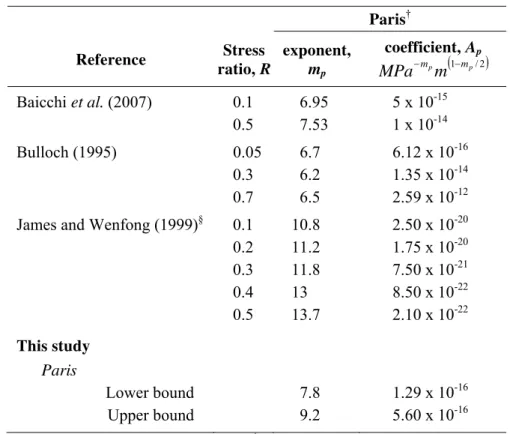
Over the past several years, values for constants Ap and mp that correspond to the Paris crack growth
expression have been published for different cast irons. These values for different stress ratios, R, are sh in Table 1. In general, caution should be exercised when comparing constants from different cast irons since
own they all have their own metallography, which can significantly influence fatigue properties.
Table 1. Fatigue constants for Paris fatigue expression.
Paris† Reference Stress ratio, R exponent, m coefficient, A p p (1 p/2) p m m m − − MPa Baicchi et al. (2007) Bulloch (1995) 0.05 6.7 6.12 x 10⁻¹⁶ 1 1 ong (1999)§ 1 1 1 his study Paris Lower bound Upper bound 9.2 5.60 x 10⁻¹⁶ 0.1 0.5 6.95 7.53 5 x 10 1 x 10-14 -15 0.3 6.2 1.35 x 0-14 0.7 6.5 2.59 x 0-12James and Wenf 0.1 0.8 2.50 x 10⁻²⁰ 0.2 1.2 1.75 x 10⁻²⁰ 0.3 1.8 7.50 x 10⁻²¹ 0.4 13 8.50 x 10⁻²² 0.5 13.7 2.10 x 10⁻²² T 7.8 1.29 x 10⁻¹⁶
† Unit for stress intensity factor is MP m and for length dim sion is . § Constants estim hical ots.
2.3 Load s
Implicit in the applications of equations [1] (in range form) and [3] that describe fatigue crack propagation, is the assum tion that alternating stress has a constant amplitude. Cast iron water mains can experience
o swelling soils and frost heave, if
c ured d history ich 85 a√ en m
ated from grap pl
pectra and stress histories for cast iron mains
p
stresses due to operational water pressure, earth loads (loads due t
applicable), pipe self-weight, fluid content, traffic loads and transient (surge or water hammer) pressures. Earth loads, pipe self-weight and fluid content can be safely assumed to be static while all other types of loads are random events that occur at different frequencies. In addition, frost loads will be imposed during winter on pipes buried in soils susceptible to frost heave. Traffic loads and transient pressures are
man-induced and depend largely on usage and operational practices, respectively.
As discussed above, load history and consequent stresses need to be determined to conduct a realisti fatigue crack propagation analysis. The load history of random events is usually generated from meas load spectra, i.e., measurement of the frequency with which each load is expected to occur. The loa of random events can be complex and needs to be reduced to a number of constant amplitude events, wh involves a process called cycle counting. Many different cycle counting methods have been proposed and Bannantine et al. (1990) provide details on these methods. Broek (1988) commented that it was more important to get the maxima and minima right than the specific method to count cycles. ASTM E
1049-(2005) standard that describes the rainflow method for cycle counting was used here together with AFGROW.
Table 2 shows the six principal different loads or stresses that a buried pipe might experience, of which earth load, pipe self-weight and fluid content are static while the others have expected frequencies that vary from several events an hour to several events a month. A truck will have two or more axels and the loads
d t and
n st ective
ater pressure fluctuations below and above the mean operating r, fFL,
ented
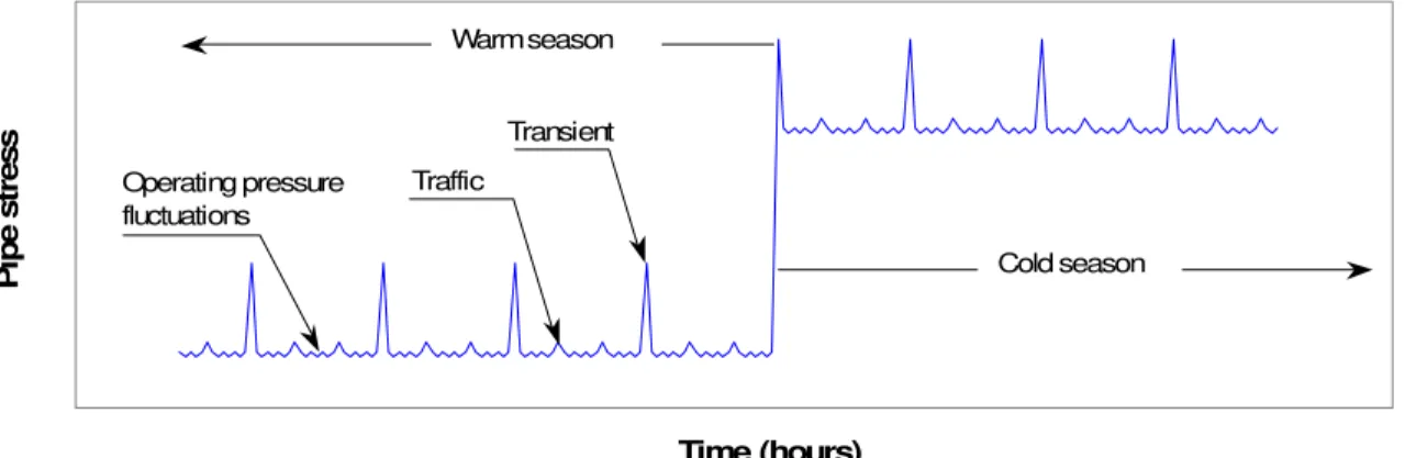
. t mean stresses in the cold season are higher than in the warm season only if the
riod
2.4 C
The software application, AFGROW, developed at the US Air Force Wright Aeronautical Laboratories ue crack propagation analysis. AFGROW has many is but only a few selected features judged to be
ns ad imposed by each axel on the buried pipe will occur within seconds. For fatigue analysis, it is sufficient to consider the loads imposed by the two axels as one event since the change in stress in the pipe when the second axel passes is insignificant. The transient pressure wave event will typically reach peak pressure an attenuate over a few seconds. As for traffic loads, only the peak pressure is treated as an event. Fros swelling loads will raise the mean stress during part of the year if the pipes are geographically located i areas affected by cold season/frost susceptible soils or rainy season/swelling clays conditions. Contrary to traffic and transient pressure, seasonal loads will develop over a number of weeks. For simplicity, the fro and swelling loads are assumed to begin and die out instantaneously, at the start and end of the resp seasons.
The different loads experienced by the pipe can be combined to simulate loading history. In lieu of measured load history, a partial list of a total of 24 possible load combinations is shown in Table 3. Additional load combinations that reflect w
pressure are not shown here. Frost load, if any, is introduced in the load combination through a facto between 0 and 1 applied to the earth load. The fluctuations in the operating pressure (Δpmo) are repres
through a factor, fmo, between 0 and 1, which is applied to the mean operating pressure (pmo), i.e., Δpmo= pmo
(1 + fmo).
Figure 5 shows a typical stress history that a buried main would experience if earth, frost, traffic and transients loads are considered. The stresses are exaggerated so that stress variations are visually noticeable It is important to note tha
ground freezes and their impact will depend on the properties of native and backfill soils, and on the pe of sustained temperatures below freezing point.
Time (hours)
P
ip
Warm season
Transient
ress Operating pressure Traffic fluctuations
e st
Cold season
Figure 5. Variations (qualitative) of pipe stress as a function of operational and seasonal loads.
rack growth prediction using AFGROW
(Harter, 2008) is used in this study to conduct fatig features to conduct a comprehensive fatigue analys
applicable to the fatigue analyses of cast iron pipes are discussed here. These features are (i) specificatio of crack size and its location, (ii) fatigue material properties discussed in sections 2.1 and 2.2, and (iii) lo spectrum discussed in section 2.3.
Table 2 Combinations to generate load spectrum for fatigue analysis of a burie
Load or stress Expected frequency ofevent(s)
d main.
CommentEarth load, pipe Static Defines mean stress in the pipe self-weight, fluid
Frost load One Assumed to starts as soon as ground begins to nd reduces to zero soon after ground thaws. Frost load effectively raises the mean stress in the pipe during the cold
ad g
ed oad uring Traffic load Several events/hour
Operational pressure
Several events /day
ional
the ilure of pumping station. content
event/year
freeze and peaks in mid-winter a
season.
Starts as soon as the moisture in the surroundin soil the pipe increases which is typically expect to happen during the rainy season. Swelling l effectively raises the mean stress in the pipe d Swelling lo One events /year
the rainy season.
Frequency will be high during peak traffic hours. Typically operational pressure will fluctuate several times an hour around the mean operat pressure.
Transient pressures
Several events/ month
Occurrence of transient pressure in trunk mains is largely dependent on hydraulic design and on operational issues such as opening and closing of valves, power-out or fa
Table 3 Expected frequency
No Load combination Comment
of loading events for a buried main.
1 & 2 Earth load, etc, (We (1 + fFL)) + mean
operational pressure (pmo)
Mean (normal) operating conditions. 3 & 6 Earth load (We (1 + fFL)) + mean
operational pressure (pmo) ± fluctuations of
operational pressure (Δpmo)
Operating conditions where water pressure fluctuates around the mean operating pressure.
7 & 8 Earth load, etc, (We (1 + fFL)) + mean
operational pressure (pmo) + transient
pressures (pt)
Conditions when transient pressure occurs with the mains operating at normal conditions.
9 & 10 Earth load (We (1 + fFL)) + mean
operational pressure (pmo) + traffic load
(Wt)
Conditions when traffic passes overhead with the mains operating at normal conditions.
(i) Crack size and its location: AFGROW allows the consideration of many different options for the type of structure to analyse, i.e., plate, pipe, etc as well as the location of the crack (defect or flaw) and its size. However, it lacks the option for pipe sizes typically encountered in the water industry and moreover
considers pipes
AFGROW, recommends that it is adequate to treat the pipe wall as a thin plate for practical purposes. Glinka’s assertion wa cting preliminary analyses using dimensions close enough to
th thi n thick ipe
(ii) Fatigue
as thin-wall cylinders. Glinka (2009), who developed the f(g) functions implemented in s confirmed by condu
at of a n pipe for AFGROW to co sider it as a material properties
p .
: AFGROW allows the consideration of several crack growth models. Each
of these mo a meters. In odel with
λ ris’ operties required to conducted crack growth analyses are plane st re toughness, threshold fracture toughness and tensile failure stren , R, is considered sufficient test data were
n abl ts on st
(iii) Stress (
dels has its own const nts and para
model) was considered. Other material pr rain fracture toughness, plane stress fractu
gth. The shift due to stress ratio
this study, only Walker’s crack growth m
approximately since =1 (Pa
ot avail e for rigorous consideration of its effec load) spectrum
ca iron. : AFGROW allows the
cle load history
input of on
cycle-by-cy . A normalized stress (load) spect discussed in section 2.3)
f p perational p ess fic loads. The
facility prov ed stress
multiplicati tor (SMF) is used to conduct fatigue analys
th
e e re 3. istory is normalized with respect to the maximum stress.
ment as a function of number e or more sub-spectra to specify
rum is generated (as rom the s ecified frequencies of changes in o
ided by AFGROW to scale the normaliz on fac
r ures, pressure transients and traf (load) spectrum through the stress is.
3. ANALYSIS OF FATIGUE FAILURE IN CAST IRON MAINS
Tables 4 and 5 list all the input parameters used the analysis. These include pipe properties, operational, trench and traffic conditions, and mechanical properties (including constants for the different crack grow models). To reflect aleatory uncertainty, most input parameters are provided in the form of most likely value plus or minus expected variation. The steps followed to conduct the analysis were:
1. Specify pipe size, burial depth, etc.
2. Specify the appropriate Walker’s (if λ = 1 then Walker’s expression reverts to the Paris’ expression) constants for cast iron. Alternatively, AFGROW allows for tabular input of da/dN vs. ΔK that would b typically obtained from test results.
3. Specify mean operating pressure and type of traffic loading. Also specify if ground is expected to freez or swell, as appropriate.
4. Assume the expected frequency of events for operating pressure fluctuations, traffic loads, and pressu transients. If the event frequencies are available from field measurements, then these should be used. 5. Determine maximum stresses experienced by the pipe for load combinations indicated in Table 6. Generate a stress history (referred to as spectrum in AFGROW) with the stresses determined in step 5
and expected frequencies specified in step 4. Typically, the stress h 7. Execute AFGROW with the above data to obtained crack growth develop
of cycles.
For practical purposes and to reduce computational effort, fatigue crack growth analysis in cast iron pipes was terminated if the fatigue life (or equivalent number of cycles) exceeds 300 years, as a pipe with a fatigue life that long would not be of immediate concern.
Table 4
Pipe properties, operational, trench and traffic conditions.
Parameters
(MLV) variation (EV)
Most likely value Expected
48” cast iron pipe Bell flange Spigot
ft) 2,438 (8’) -
crown of pipe), mm 900 10%
backfill)
0.4 -
Operational conditions
Mean operating pressure and its fluctuations (%) 3.45 bars (50 psi), 20% Period of mean pressure fluctuations, per event 12 hour Design transient pressure and % of design
transient pressure
6.89 bars (100 psi), 60% Period of transient pressures, per event 1 day
Traffic conditions
No of passing trucks 2
Traffic type Heavy
Period of traffic (truck loads), per event 1/2 hour
Inside diameter, mm 1,241.4 1,21 -
Wall thickness, mm 72.2 28.7 5%
Trench width, mm 1,800 10%
Pipe segment length, mm (
Trench conditions
Pipe burial depth (to
Backfill unit weight, kg/m3 1,800 10%
Laying conditions as per AWWA C101-77 A Coefficient of sliding friction (trench wall &
The following only discusses the analysis of through crack at bell flange (thickness and outermost part of bell) of 48” pipe. The stress history generated for 48” diameter cast iron main operating under conditions and parameters specified in Tables 4 and 5 resulted in hoop stresses in the 5.2 to 10.6 MPa range for the spigot end and 23 to 42.3 MPa range for the bell flange. It is likely that actual stresses may have been even higher because typically, aggressive compaction of lead caulking was very likely to put the bell flange in tension (this tension was not considered in the current analysis). The threshold fracture toughness was taken as 2 MPa√m.
The stresses had to be increased by about 3.5 times (SMF = 3.5) the estimated stresses under normal operating loads to obtain fatigue lives of less than 300 years. This indicates that the bell has to be severely stressed if the bell failure is to be explained by a fatigue mechanism. Table 6 exhibits the results of the analyses conducted for 48” bell flange as discussed below.
(a) Fatigue life of the 48” cast iron pipe decreases as the length of initial crack length increases.
(b) Fatigue analyses were only conducted for the upper bound of the da/dN vs. ΔK curves since these led to fairly short fatigue lives. Lower bound da/dN vs. ΔK lead to even higher fatigue lives, which indicates that pipes with very low values of Ap may deemed to be safe from fatigue failure.
Table
tudy.
(MLV)
ed V)
5.
Mechanical properties for cast iron pipes for fatigue sensitivity s
Parameters Most likely
value
Expect variation (E Hyperbolic parameters for cast iron
Pa 1 %
re,
Elastic modulus, Eo, G 20 10
Tensile strain at failu σfT, %
ure,
0.6 10%
Tensile stress at fail εfT , MPa 185 10%
Compressive strain at failure, σfC , % 0.9 15%
Compressive stress at failure, εfC, MPa 278
Fr on
12 10%
24 10%
Threshold fracture toughness, ΔKth, MPa√m 2 20%
bou d) 7.8, 1.29 x 5%, 5%
per bound) 9. , 5%
10%
acture toughness for cast ir
Plane strain, KIc, MPa√m
Plane stress, Kc, MPa√m
Fatigue Paris constants for cast iron †
Fatigue exponent and coefficient, mP, AP (lower n 10-16
Fatigue exponent and coefficient, mP, AP (up 2, 5.6 x 10⁻¹⁶ 5%
† U and for length dimension is m.
(c) h, af, was first determined to be 26.28 mm based on the mechanical properties
Table 4 and the given stress condition defined above. The range of initial crack size ratio, sponds to range o ck lengths of between 26.02 and 26.15 mm, respectively.
ell e the variation in the estimates of fatigue lives for the 48” bell flange
lots.
n nit for stress intensity factor is MPa√m
The final crack lengt
specified in s
ra, was varied between 99% and 99.5%, which corre f initial cra
(d) The bell flange wall thickness is much higher than spigot wall thickness. Consequently, stresses due to operational loads at the bell end are much lower than induced in the barrel or the spigot end. However, as discussed above, lead-caulking action can elevate the stresses beyond what would be induced due to operational loads alone. The effect of the increase in stresses was incorporated in the fatigue analysis through the stress multiplication factor (SMF) provided in AFGROW. The analyses show that the b end needs to be highly stressed to lead to fatigue life of less than 300 years.
Monte Carlo simulations to determin
were conducted, and results are exhibited in Fig. 15 in the form of frequency distribution (histogram) p Analysis indicates that given a crack length of 26.15 mm, fatigue failures are likely to occur (with a relatively high likelihood of nearly 60%) within the first 50 years. It is important to note that this relatively short fatigue life results because extreme conditions were imposed especially in regards to the stresses i the bell flange.
Table 6 Estimates of fatigue life for bell flange of 48” cast iron pipe.
Crack growth model Fatigue life a funcs tion of initial crack sizeStress range, (MPa) and SMF
99.0
σ 5.2 to 10.6 an
0% 99.25 99
d SMF = 3.5
Initial crack size ratio, ra % .50%
Paris
1,384,896 1,03 6 6
Upper bound, T (years) 79 59 39
Upper bound, Nf (cycles) 4,256 87,69
f
r uring,
he cast
e usive understanding of fatigue growth failures in cast iron trunk mains. The outcome of the application of crack growth models should be judged from a qualitative aspect. The nature of the fatigue analysis is based on considerable empirical relationships and, wherever possible, physical evidence should be sought to confirm fatigue failure. It is recognized that this exercise is not easy and not always possible to pursue rigorously.
0.0 0.2 R e 0.4 1.0 0 200 400 600 v 0.6 que nc 0.8 y la ti e f re
Fatigue life (years)
Figure 6. Histogram of fatigue life of 48” CI pipe bell flange with Paris model (ai = 26.15 mm).
3. FINAL REMARKS
It is important to note that a cast iron main can only undergo fatigue failure if the pipe has existing cracks o voids. Previous analyses show that if the cast iron mains were free of cast iron defects due to manufact then cracks could still have been introduced during the loading/unloading delivery process or during the lead caulking of the bell-spigot joint, with a high likelihood of not being noticed on installation and commissioning.
Analysis shows that long fatigue life is assured if an existing crack size is below a certain limit and t iron main is operating under conditions that generate low stresses. Therefore, from an inspection viewpoint, it is crucial to detect cracks that exceed this length limit if sudden failure (uncontrolled crack growth propagation) is to be avoided.
The fatigue crack model described in this paper allows the consideration of a wide variety of scenarios. Th analysis described here only consider one specific scenario and a thorough sensitivity study needs to be carried to reach more concl
Thi o-sponsored by the authors wish to acknowledge the invaluable help provided by Dr. Ahmed Abdel-Akher at the NRC to implement the algo
rences
Am
Society for Testing and Materials (ASTM). (1990). Standard test method for
plane-strain fracture toughness of m
terials
, ASTM E 399-90. ASTM International,
West Conshohocken, PA.
erican Society for Testing and Materials (ASTM). (2005). Standard practices for cycle
counting in fatigue analysis
, ASTM E 1049-85. ASTM International, West Conshohocken, PA.
aicchi, P., Collini, L. and Riva, E. (2007). “A methodology for the fatigue design of notched
castings in gray cast iron.” Engineering Fracture Mechanics. Vol. 74, pp. 539–548.
annantine, J. A. Comer, J.J. and Handrock, J. L. (1990). Fundamentals of metal fatigue analysis.
Prentice Hall, Englewood Cliffs, NJ.
onacuse, P. J. (2001). Fracture of cast iron pipes. Supporting document in Cleveland Trunk Main
Task Force Final Report. City of Cleveland, Division of Water, OH.
roek, D. (1988). The practical use of fracture mechanics. Kluwer Academic Publishers, Boston,
MA. 522 p.
rooks, C.R. and Choudhury, A. (1993). Metallurgical Failure Analysis. McGraw Hill, New
York. N.Y.
ullock, J.H. (1995). “Near threshold fatigue behaviour of flake graphite cast irons
microstructures.” Journal of Theoretical and Applied Fracture Mechanics, Vol. 24, pp. 65-78.
Cast
as,
steam, air, chemical and abrasives
. Chicago. IL.
ent. (2001). Cleveland Trunk Main Task Force Final Report. City of
).
d.
cott, W. and James, R.W. (1930). Burst water mains. Report
g
Acknowledgment
s research project was c Thames Water Utilities Ltd and the NRC. The rithms described in this paper.