HAL Id: hal-02396199
https://hal.archives-ouvertes.fr/hal-02396199
Submitted on 25 Nov 2020
HAL is a multi-disciplinary open access
archive for the deposit and dissemination of
sci-entific research documents, whether they are
pub-lished or not. The documents may come from
teaching and research institutions in France or
abroad, or from public or private research centers.
L’archive ouverte pluridisciplinaire HAL, est
destinée au dépôt et à la diffusion de documents
scientifiques de niveau recherche, publiés ou non,
émanant des établissements d’enseignement et de
recherche français ou étrangers, des laboratoires
publics ou privés.
Dynamic of Space Charge in Electron-Beam Irradiated
Cross-Linked PolyEthylene
Virginie Griseri, G. Teyssedre, N. Saidi-Amroun, S. Mouaci, C. Mouchache,
M. Saidi
To cite this version:
Virginie Griseri, G. Teyssedre, N. Saidi-Amroun, S. Mouaci, C. Mouchache, et al.. Dynamic of Space
Charge in Electron-Beam Irradiated Cross-Linked PolyEthylene. 2018 IEEE 2nd International
Con-ference on Dielectrics (ICD), Jul 2018, Budapest, Hungary. pp.1-4, �10.1109/ICD.2018.8514702�.
�hal-02396199�
Dynamic of Space Charge in Electron-Beam Irradiated
Cross-Linked PolyEthylene
V. Griseri, G. Teyssèdre
Université de Toulouse LAPLACE – UPS, CNRS, INP
118 route de Narbonne, 31062 Toulouse (France) [email protected]
N. Saidi-Amroun, S. Mouaci, C. Mouchache, M. Saidi
University of Sciences and Technology (USTHB) Material Physical Laboratory Physics faculty BP 32 El-Alia, Bab-Ezzouar, Algiers (Algeria)
Abstract—The electrical properties of Crosslinked
PolyEthylene –XLPE- material have been studied for many years as it is used for cable applications. In this work, XLPE peelings, previously submitted to thermal ageing are investigated under electronic irradiation. FTIR spectra did not reveal specific thermal ageing signatures. The space charge distribution has been analyzed by Pulsed Electro-Acoustic method during and after application of a DC field. The space charge profiles appear to be very dependent on the electron beam energy that determines the electron penetration depth and irradiated volume. Most of the space charge features appear linked to charge redistribution in the bulk following irradiation.
Keywords— Space Charge, Pulse Electro-Acoustic Method, Electron Irradiation, Polarization
I. INTRODUCTION
The Cross Linked Poly-Ethylene (XLPE) has been studied for a long time as it is commonly selected for the design of insulation in energy transmission systems. These cables are developed to be used under DC or AC stresses. However the XLPE electrical properties are still not fully understood. Insulated cables can be installed in radiative environment. In the present paper we propose to study XLPE behavior when submitted to an electronic irradiation. In this case, charges are deposited in the bulk due to the primary electron deposition. Besides, electron-hole pairs are created and constitute a further source of charges. We have chosen to follow the space charge distribution by the Pulse Electro Acoustic (PEA) method just after the irradiation to check the charge deposition then during a polarization under DC field and during the relaxation.
During the irradiation some structural modifications can happen to the polymer. They might be at the origin of some properties modifications. However, it is obvious that just after irradiation the presence of the charges in the bulk is modifying considerably the behavior of the charge injection and transport from the electrode during polarization and relaxation. The behavior of the charges will be described in details and analyzed. Complementary analysis by Fourier-Transform Infra-Red spectroscopy (FTIR) will be presented in this paper. The purpose is to determine if there is a link between the electrical behavior and the chemical structure of the sample. Indeed, thermal ageing mainly can produce structural evolution of the material with time.
II. EXPERIMENTAL SET-UP
A. Sample selection
XLPE samples were taken from rolls issued from HV cable peelings produced in the frame of the Artemis project [1, 2]. The peelings, 150 µm in thickness and 80 mm wide, were taken from a cable previously aged for 4600 h under a ac voltage of 225 kV under a thermal gradient, with maximum temperature of 90°C at the inner semiconducting layer. Details on samples source are given elsewhere [2]. It was considered that the ageing induced to the material cable is negligible especially as its insulation properties were not downgraded. This is substantiated by presented FTIR results.
In this work space charge measurements were achieved by PEA method using a set-up adapted to the XLPE film thickness. Measurements are realized after electron deposition in the bulk by irradiation at various depths.
B. The irradiation chamber: Matspace
The irradiation chamber called Matspace, which is equipped with a 100 keV electron beam was used [3]. The irradiation was performed under vacuum on the whole surface of the sample
with a homogenous flux of about 1 nA/cm2. The irradiation
time was limited to 10 minutes to avoid surface discharges. After the irradiation, the sample was taken out of the chamber at atmospheric pressure for further investigations.
C. Space charge measurements
The classic PEA [4, 5] device available in the laboratory, provided by FiveLab has been used as a polarization and relaxation protocol was applied. The measurements were performed at atmospheric pressure at a controlled temperature of 25°C. The polarization voltage was applied through the semiconducting film attached to the top electrode whereas the Aluminum bottom electrode was grounded.
The first set of space charge (SC) results was recorded on a virgin sample. Space charge density profiles were recorded for 1 h while the sample was polarized under a field of 40 kV/mm. Afterwards, the signal was recorded for an extra hour under Volt-off to probe the charge release. A second set of samples has been irradiated with an electron beam before polarization. Two energies have been selected: 40 keV and 100 keV. The
idea was to inject charges at different depths. For an energy of 40 keV, electrons are expected to be injected just beneath the irradiated surface whereas the 100 keV electrons are expected to be deposited up to a depth approaching the back surface of the 150 µm thick sample.
D. Fourier-Transform Infra-Red Spectroscopy (FTIR)
To investigate the impact of the thermal aging on the chemical structure the FTIR method has been implemented. FTIR analyses were performed on a VERTEX 70 fully digital infra-red (IR) spectrometer designed for data acquisition in the
mid IR region (400-4000 cm-1) with a resolution of 2 cm- 1. The
transmission mode was adopted for the measurement of the spectrum.
III. RESULTS AND DISCUSSION
A. Space charge profiles on the virgin sample
The first measurements by PEA on XLPE films have been performed on non-irradiated sample. During the polarization under 40 kV/mm we can see on Fig. 1 that both peaks on the electrodes are not symmetrical. This is due to a broad attenuation of the signal in the bulk. However, we can observe clearly a negative charge injection from the ground electrode (in the region 30-60 µm) which is growing slowly with time. We also notice a small negative charge accumulation near the HV electrode (right) which tends to decay with time.
During the relaxation (Fig. 2) we can observe that the small amount of negative charges injected near the ground electrode is decaying with time. Therefore, the positive induced charges on the electrodes are also decreasing slowly during the relaxation. After one hour of relaxation a small amount of negative charges is still detected in the volume. One can expect that after a few hours of relaxation most of the charges have been extracted or recombined.
B. Space charge profiles on irradiated samples
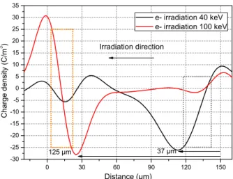
Space charge measurements were performed after irradiation on samples just after removal from the vacuum chamber. The irradiation energy was either 40 keV or 100 keV. On Fig. 3 we can see that in both cases a broad peak of negative charges is detected in the bulk. In the case of the 40 keV irradiation the peak maximum is detected at about 37 µm from the irradiated surface whereas after the irradiation under 100 keV the peak maximum is observed at about 125 µm. Theoretically the maximum penetration depth (under continuous slowing down approximation -csda) of the 40 keV electrons is expected at about 30 µm. In the present case electrons seem to have been injected deeper than expected in the bulk as they are detected up to 50 µm from the surface. The difference can be explained in part by the transport of charges under the field induced by the charges. For electron energy of 100 keV, the charge peak is found at about 125 µm from the surface, which is less than the csda for this energy (approximately 140 µm [6]). One has to realize first that the csda is the maximum penetration depth; hence the majority of electrons are stopped before that range. Second, the influence charge on the ground electrode superimposes to the deposited charge. Given the fact that the spatial resolution is not at the best for the relatively thin films treated here, it is not surprising to find the main peak at this position.
Fig. 3 Charge density profiles recorded on a 150 µm thick XLPE film after irradation under 40 and 100 keV electron beam for 10 min with a
flux of 1 nA/cm2 in the irradiation chamber MATSPACE.
0 30 60 90 120 150 -30 -25 -20 -15 -10 -5 0 5 10 15 20 25 30 35 125 µm C har ge de ns ity ( C /m 3 ) Distance (µm) e- irradiation 40 keV e- irradiation 100 keV Irradiation direction 37 µm
Fig. 1 Charge density profiles recorded by PEA on a 150 µm thick-XLPE film polarised under 40 kV/mm for 1 h. Left: ground electrode (cathode); Right: HV electrode (anode).
Fig. 2 Charge density profiles recorded by PEA during relaxation on a XLPE 150 µm-thick after 1 h polarisation under 40 kV/mm.
-30 0 30 60 90 120 150 180 -30 -25 -20 -15 -10 -5 0 5 Char ge den si ty ( C /m 3 ) Distance (µm) 1 h - Polarisation 40 kV/mm -30 0 30 60 90 120 150 180 -1 0 1 2 1 h - Relaxation Distance (µm) Char ge dens ity ( C /m 3 )
C. Space charge profiles with polarization of irradiated samples
Fig. 4 shows the results with 40 kV/mm field applied after sample irradiation under 40 keV. The applied field is such that the initially stored charge should be repelled towards the irradiated side of the sample (anode to the right). As soon as the polarizing field is applied the peak of previously stored negative charges starts to decrease. After the quick formation of a positive peak in the bulk near the ground electrode (left) a continuous decay is also observed. The peaks of influence charges on both electrodes are also decaying continuously during the polarization due to internal charges redistribution.
During Volt-off (Fig. 5) the same decaying processes are observed. However, after 1 h of relaxation the position of the initial negative charge cloud deposited by the electron beam is still clearly observed. This peak is remaining at the same location without spreading. Only the amplitude has been modified during the polarization step.
The behavior of the sample irradiated under 100 keV is very different from that of the sample irradiated under 40 keV. During polarization, cf. Fig. 6, the formation of a prominent positive peak at 40 to 50 µm from the ground electrode is observed. Concomitantly, a negative charge peak grows up adjacent to the right electrode. With these features, the position of the charge cloud deposited initially shifts to the ground electrode. This corresponds most probably to an apparent shift, linked to the growing up of the positive peak and the partial superposition of the positive and negative charge clouds. The influence charge on the ground electrode grows progressively. It is weak in the first instants as the (positive) image charge of the previously stored negative charge is annihilated by the (negative) capacitive charge of the cathode. On the irradiated face (anode), the positive influence charge does not appear distinctly, owing to the presence of the negative charge in the bulk. A probable mechanism occurring in the irradiated region is the motion of the charge pairs created during the irradiation due to deposited dose. Positive charge would be driven towards
Fig. 4 Charge density profile on a 150 µm-thick XLPE film during 1 h
polarisation after irradiation under 40 keV for 10 min. Applied
field=40 kV/mm. Irradiated face to the right.
Fig. 5 Charge density profiles recorded on 150 µm-thick XLPE film during the relaxation after the irradiation under an electron beam of 40 keV and 1 h polarisation under 40 kV/mm.
-30 0 30 60 90 120 150 180 -40 -35 -30 -25 -20 -15 -10 -5 0 5 10 15 20 25 Ch ar ge d ens ity ( C /m 3 ) Distance (µm) -30 0 30 60 90 120 150 -35 -30 -25 -20 -15 -10 -5 0 5 10 15 20
Profiles during relaxation
Initial Charge profile after irradiation Cha rge dens ity ( C /m 3 ) Distance (µm)
Last profile during polarisation -30 0 30 60 90 120 150 -40 -35 -30 -25 -20 -15 -10 -5 0 5 10 15 20 25 Char ge d ens ity ( C /m 3 ) Distance (µm)
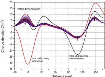
Fig. 6 Charge density profiles recorded on 150 µm-thick XLPE polarised under 40 kV/mm for 1 h after an electron irradiation under 100 keV during 10 min.
Fig. 7 Charge density profiles recorded on 150 µm-thick XLPE film during the relaxation after the irradiation under an electron beam of 100 keV and 1 h polarisation under 40 kV/mm.
-30 0 30 60 90 120 150 -45 -40 -35 -30 -25 -20 -15 -10 -5 0 5 10 15 20 25 30
Profiles during relaxation
Initial Charge profile after irradiation Char ge dens ity ( C /m 3 ) Distance (µm)
Last profile during polarisation
the non-irradiated regions and negative ones towards the irradiated face. The amounts here are roughly of the same amplitude.The region which was initially neutral lets then appear a net charge.
During Volt-off, Fig. 7, both positive and negative charge peaks detected in the bulk slowly decay. The positive peak at 35 µm shifts slightly to the left; the negative one at 140 µm slightly to the right. Presumably, charges are repelled and recombined, or at least neutralized so as to form zero net charge regions. It is not clear whether the so called radiation induced conductivity in irradiated materials is linked to the formation of electronic carriers which are then involved in transport or to the creation of defects that assist transport of injected carriers. The space charge signal could be interpreted in the first case by the dissociation of pairs and the redistribution of ionic or electronic carriers. In the second case it may reflect conductivity gradient in the insulation.
D. Discussion
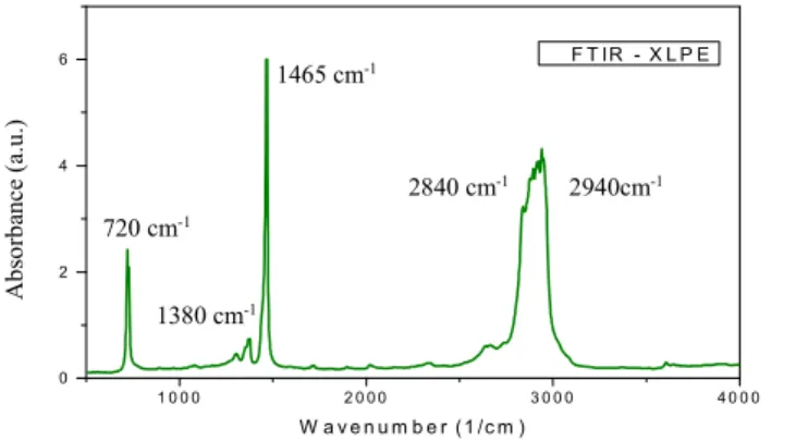
It is worth commenting on the state of samples used for the present characterizations, first because they were previously electro-thermally aged, second because they were stored under ambient conditions for about 15 years prior to irradiation. The FTIR spectrum of the investigated samples (before irradiation) is shown in Fig. 8. Compared to typical spectra reported in the literature[1, 7] there is not significant change in the characteristic peaks of XLPE. The most important bands are
found, as the shear-type vibration of C-H bond of the CH2
group at 720 cm-1and at 1468-1472 cm-1(for the crystalline
phase), and the 2852 and 2916 cm-1 bands due to C-H bond of
symmetric and antisymmetric elongation of the CH2 group [8].
The ageing (at T = 90°C) and storage of the XLPE sample does not have an effect on the disappearance or the creation of new bonds, such as the carbonyl groups. The ATR mode spectrum did not reveal either specific signature at the surface.
There are at least 4 possible contributing processes to charge build-up in our conditions of irradiation and
measurement that are: i/ primary electron deposition, at
positions that are predictable and depend mainly on electron beam energy; ii/ electron-hole pair generation during irradiation followed by separation and transport under field application; iii/ positive charge injection at the ground electrode during
irradiation (due to field created by implanted charges) and then negative charge injection under field when ground electrode is cathode; iv/ positive charge injection from irradiated face when top electrode is anode; v/ enhanced carrier mobility in the irradiated region producing space charge due to non-homogeneous conductivity. According to the present results, charges are relatively deeply trapped in the bulk and do not relax in a period of one hour. It seems relatively clear that dissociation of created electron-hole pairs is at the origin of the main features obtained for 100 keV electrons, besides primary electron deposition. However, the charge amount created by dissociation is not easy to anticipate [9] since most of the created pairs may recombine quickly.
IV. CONCLUSIONS
The effects of the irradiation on charge injection and transport in XLPE films are highly dependent on the initial charge deposition depth. Bulk transport was observed on the sample irradiated with high energy electron beam. Besides, the accumulation of charges at the sample-electrode interface seems to confirm that we are dealing with bulk effects more that interface effects. No specific structural changes were detected by FTIR. Complementary physico-chemical analyses are necessary to reveal if there is a direct link between space-charge behavior in post-irradiation and material structure.
ACKNOWLEDGMENT
The work is supported by French-Algerian Tassili research program in the frame of Partenariat Hubert Curien (PHC).
REFERENCES
[1] J. C. Fothergill et al., "Electrical,microstructural, physical and chemical characterization of HV XLPE cable peelings for an electrical aging diagnostic data base", IEEE Trans. Dielectr. Electr. Insul., vol. 10, pp. 514-527, 2003.
[2] G. Teyssedre, C. Laurent and G.C. Montanari, "Semi-quantitative analysis of photoluminescence in thermoelectrically aged cables: II-Analysis of a population of cables", IEEE Trans. Dielectr. Electr. Insul., vol. 16, pp. 1189-1198, 2009.
[3] V. Griseri, P. Malaval, L. Berquez, T.A. Tung, S. Le Roy, L. Boudou and A. Boulanger, "Charge build-up and transport in electron beam irradiated polymers in a new irradiation chamber", Proc. IEEE-CEIDP, pp. 688-691, 2010
[4] T. Maeno, T. Futami, H. Kushibe, T. Takada and C. M. Cooke, "Measurement of spatial charge distribution in thick dielectrics using the Pulsed Electroacoustic method", IEEE Trans. Electr. Insul., vol. 23, pp. 433-439, 1988.
[5] Y. Li, M. Masuda and T. Takada, "Pulsed Electroacoustic method for measurement of charge for accumulation in solid dielectrics", IEEE Trans. Dielectr. Electr. Insul., vol. 1 pp. 188-195, 2004.
[6] R.J. Woods and A. K. Pikaev, Applied Radiation Chemistry: Radiation Processing, Wiley, 1994, p. 63
[7] L. Boukezzi, A. Boubakeur, C. Laurent and M. Lallouani, "Observations on structural changes under thermal ageing of cross-linked polyethylene used as power cables insulation", Iranian Polymer J., vol. 17, pp. 611-624, 2008.
[8] J.V. Gulmine and L. Akcelrud, "Correlations between structure and accelerated artificial ageing of XLPE", Eur. Polymer J., vol. 42, pp. 553-562, 2006.
[9] M. E. Banda, V. Griseri, G. Teyssèdre and S. Le Roy, "Polarization of electron-beam irradiated LDPE films: contribution to charge generation and transport", J. Phys. D: Appl. Phys., vol. 51, p. 155303, 2018. Fig. 8 FTIR spectrum of XLPE.
1 0 0 0 2 0 0 0 3 0 0 0 4 0 0 0 0 2 4 6 F T IR - X L P E A b s o rb a n c e (a ,U ) W a v e n u m b e r ( 1 /c m ) 1465 cm-1 2840 cm-1 2940cm-1 720 cm-1 1380 cm-1 A bs or ba nce (a. u. )