HAL Id: hal-01817163
https://hal.univ-lorraine.fr/hal-01817163
Submitted on 24 Jul 2019
HAL is a multi-disciplinary open access
archive for the deposit and dissemination of
sci-entific research documents, whether they are
pub-lished or not. The documents may come from
teaching and research institutions in France or
abroad, or from public or private research centers.
L’archive ouverte pluridisciplinaire HAL, est
destinée au dépôt et à la diffusion de documents
scientifiques de niveau recherche, publiés ou non,
émanant des établissements d’enseignement et de
recherche français ou étrangers, des laboratoires
publics ou privés.
Effect of supercapacitors directly hybridized with
PEMFC on the component contribution and the
performance of the system
Divyesh Arora, Karine Groos-Gérardin, S. Raël, Caroline Bonnet, François
Lapicque
To cite this version:
Divyesh Arora, Karine Groos-Gérardin, S. Raël, Caroline Bonnet, François Lapicque. Effect of
su-percapacitors directly hybridized with PEMFC on the component contribution and the performance
of the system. Journal of Applied Electrochemistry, Springer Verlag, 2018, 48 (6), pp.691 - 699.
�10.1007/s10800-018-1188-0�. �hal-01817163�
1
Effect of supercapacitors directly hybridized with PEMFC on the component contribution and the performance of the system
D. Arora1,2, K. Gérardin1, S. Raël2,1 *, C. Bonnet1, F. Lapicque1
1Laboratory for Reactions and Chemical Engineering, CNRS – Univ. Lorraine, ENSIC, BP 20451, F-54001- Nancy, France; +33 372 743 761
2Group of Research in Electrical Engineering of Nancy (GREEN), Univ. Lorraine, 2 Avenue de la Foret de Haye, BP 90161, F-54505 Vandœuvre-lès-Nancy, France; +33 372 744 377
Abstract
Hybridization of a fuel cell (FC) with energy storage systems such as supercapacitors (SC) or batteries can make the fuel cell withstand the sudden fluctuations of the current. Moreover, direct hybridization of a FC with SCs (i.e. without power converters) has further proved out to be a better solution than the indirect mode (i.e. with power converters), in addition without inducing further ageing of the cell in non-steady operations. The present investigation was aimed at comparing the performance of the system in terms of yield and the component contributions of the fuel cell and the supercapacitor in power conversion on increasing the capacity of energy storage. A single 100 cm2 cell was directly hybridized to one or three 3000 F SCs in standard fuel cell dynamic load cycling operation, simulating the energy demand in urban transport with current varying in the range 0 – 100 A.
Upon comparing the hydrogen supply for the two configurations (1 or 3 SC), increasing the SC number decreased the hydrogen amount required in a cycle by approximately 5 %. This also enhanced the yield of the fuel cell and the hybrid source by 10 % and 16 % respectively. Moreover, increasing the SCs capacity reduces the power supplied by the FC in periods with high energy demand in cycling tests.
Keywords: Direct hybridization; PEMFC; Supercapacitors; Hydrogen consumption; Fuel Cell Dynamic Load
Cycling
2
1. Introduction
Global warming consciousness is increasing. The biggest contributor to global warming is the transportation sector after electricity production. Electric vehicles (EVs) are one of the promising solutions to curb the greenhouse gases emissions. However, EVs utilising batteries face a great challenge to the cost of the batteries [1], which have paved opportunities for fuel cell (FC) automobiles [2-4]. Among the FC automobiles, polymer electrolyte membrane fuel cell (PEMFC) technology is appealing to the automobile industry in a significant way due to its high energy density and its ease in start-up and shut-down of the system just by the control of the feed gases [5]. However, the biggest drawback to the system is that the PEMFC does not throttle fast enough. Actually, PEMFC slow response is due to various factors, e.g. residence time of ancillaries upstream of the cell (e.g. pipes, humidifiers), too slow response of side components such as mass flowmeters, in addition to sluggish transport phenomena in the cell structure [6]. Therefore, the gas flow rates cannot be instantaneously adjusted to their suitable levels on the request of higher generation of power. In most cases this fact can induce energy waste in the transient periods required to balance the feed gas rates.
Furthermore, as far as fuel cell systems are concerned, converters are required to increase the fuel cell voltage, along with inverters to convert direct current to alternating current. Thus, the ripples produced by the power electronic converters degrade the Membrane Electrode Assembly (MEA) and other parts of the fuel cell system, thereby impacting it categorically [7].
At this point it appears interesting to connect the PEMFC with energy storage devices (batteries or supercapacitors) for better management of transient periods. Supercapacitors (SCs) have a higher specific power than batteries; therefore, they can more effectively assist fuel cells to meet the transient power demand [8-9]. Moreover, SCs can charge and discharge rapidly and can tolerate more charge and discharge cycles than batteries. SCs thus have a longer life cycle as compared to batteries.
The connection of SCs with PEMFC is either achieved through power converters (indirect/active hybridization) [10] or can be effective by direct connection (direct/passive hybridization) [11-12]. Direct hybridization of PEMFC with SCs exhibits various advantages over active hybridization. Firstly, it reduces the weight and the size of the system and makes it simple and robust [13]. Secondly, since converters are not used in direct hybridization, power losses are reduced [14]. Thirdly, as far as the voltage of direct hybridized system is fixed by the storage device, the power contributions of PEMFC and SCs are managed automatically, and then no control algorithms are required. Another crucial consequence is that direct hybridization naturally protects the PEMFC against any fuel starvation phenomenon; therefore, it allows reduction in hydrogen consumption through the decrease of usual safety levels in the cell e.g. minimum flow rates or over-stoichiometries [13-15]. Finally, SCs directly connected to a PEMFC can absorb to a large extent the current ripples produced by power electronic converters, protecting thereby the MEA against degradation due to this side phenomenon.
Another major point, demonstrated in [16], comes from the fact that PEMFC can act as a current source at very low voltage, where the current is directly controlled by the hydrogen flow rate (after Faraday’s law). This kind of operation can occur at SCs pre-charge, or in transient operation. Moreover, long-period runs under cyclic operation, with regular evaluation of its state of health, demonstrated that hybridization to SC’s did not result in further ageing of the fuel cell. Pre-charging of SCs for such operation appears thus unnecessary [17].
3
As stated above, SCs help to provide fast system response. Moreover, introduction of SC in the charge circuit would allow power production with improved energy efficiency in non-steady, cycling operations, for which reacting gases were usually supplied with safety levels mentioned above to avoid transient starvation of the cell. Thus, this paper proposes to investigate the effect of the storage device capacitance on FC and SCs contributions to energy production, and on the efficiency of the overall system. The present study has been carried out with a 100 cm2 single PEMFC, which has been directly hybridized either with one or with three parallel 3000 F SCs. The resulting hybrid sources were submitted to the European Harmonized Fuel Cell Dynamic Load Cycle (FC_DLC) operation, simulating the energy demand in urban transport [18]. The study also highlights the effects of hybridization by comparing it with PEMFC cycling alone.
Section 2 presents the experiment materials used and operating conditions, along with the significant variables and features of the system in FC_DLC conditions. Then, the results were discussed with reference to the characteristic variables of the system such as yield and hydrogen consumption, on comparison with increasing the number of SCs (Section 3). Finally, we discuss in Section 4 the reduction in hydrogen consumption with its effect on the system energy management to definitely justify the idea of increasing the number of SCs hybridized with the PEMFC.
2. Experimental section and the methods used
2.1. Materials used and operating conditions
Tests have been conducted using a 100 cm2 PEM single cell with a seven layered MEA composed of a Nafion® 212 50 µm thick membrane, Pt/C electrodes with a 0.4 mg cm-2 and 0.2 mg cm-2 catalyst loading at the cathode and at the anode respectively, and of 285 µm thick GDLs including a macroporous carbon fiber paper and a carbon black microporous layer. The gases hydrogen and air, were supplied at anode and cathode sides respectively. The stoichiometric factors of hydrogen and air were maintained at 1.2 and 2.5 respectively at pressure close to ambient. For safety reasons in cyclic operation, it was preferred to feed both hydrogen and air with minimum flow rates corresponding to 0.2 A cm-2, considered as "safety level current" (I
SL), as usually done
in FC_DLC cycle. For the 100 cm2 cell, this means that if during the cycle, the fuel cell current is lower than 20 A, then the flow rates are set to values corresponding to 20 A according to Faraday’s law and taking into account the above stoichiometric factors. Otherwise, the flow rates are supplied as a function of fuel cell current, according to Faraday's law and stoichiometric factors. In addition, in non-hybridized mode (FC alone), the flow rates were anticipated a few seconds before each positive current step to avoid starvation during the transient of the gas flowmeters. In all tests shown here, the fuel cell temperature was maintained at 55 oC thanks to a thermostatic bath. The humidity of inlet air was kept constant at 57 % whereas hydrogen was fed dry.
The supercapacitors used for hybridization are of a conventional design, with microporous carbon electrodes, an electrolyte composed of a quaternary ammonium tetrafluoroborate dissolved in acetonitrile, and a porous polypropylene plate as separator. These devices can safely operate between 0 and 2.5 V, and the capacitance of one device is about 3000 F. To obtain higher values for capacitance, supercacitors were connected in parallel.
4
The test bench was controlled by Controldesk software with a dSPACE® real time electronic card. It was used in combination with Matlab-Simulink® mathematical environment for all necessary control functions such as reference setting (inlet gas flows and load current), data acquisition and safety shutdown. The software controls the total current and the gas flow rates were referred to the fuel cell current, with the above minimum gas flow rates. The total current was imposed by a 132 A active load (Kikusui). The PEMFC and the SCs were connected in parallel using two 0.80 m long, 9 mm diameter Stäubli cables (600 V, 125 A) provided with 6 mm plugs. The 20-minute FC_DLC cycle was submitted to the FC alone, or to the hybridized FC–SCs combinations, with the dynamic control allowed by the above control system. In the meanwhile, current and voltage of both PEMFC and SCs were measured and recorded every 0.1 s. In addition, the set points of both gas flow rates and the reference value of the load current were also recorded at this frequency.
2.3. Important variables and features of the system
Fig. 1 gives the electrical scheme of the test bench, and the associated notations. Calculations rely on the
determination of various variables and characteristic parameters, as follows:
a. Power – Fuel cell converts chemical energy into electrical energy. So the electrical power produced from
the reaction of positively charged hydrogen ions with oxygen, is known as fuel cell power. The power of the cell is defined by the product of fuel cell voltage (UFC) and fuel cell current (IFC). The cell mean power
was calculated over the cycle period T (T = 1200 s) using Eq. (1):
T FC FC mean FCU
t
I
t
dt
T
P
01
(1)The FC and the SCs are hybridized as depicted in Fig. 1, i.e. with the SCs connected as output of the hybrid source (HS). As a result, the power produced by the hybrid source can be calculated by the product of the SC voltage (USC) and the load current (Icycle). The HS mean power over one cycle was then calculated using
Eq. (2):
T SC cycle mean HSU
t
I
t
dt
T
P
01
(2)b. Energy – The electrical energy produced by the FC during one cycle is denoted by
E
FCand is expressed as shown in Eq. (3):T
P
E
FC
FCmean
(3)In the same way,
E
HScorresponds to the electrical energy produced by the hybrid source. It was calculated by Eq. (4):T
P
E
HS
HSmean
(4)c. Yield – We define hereafter the yield as the electrical energy produced per cycle over the hydrogen
consumed for its production. It is expressed in Wh of electrical energy produced / normal litres of hydrogen consumed (
V
Hconsumed5
the gas amount fed to the fuel cell as per the demand of the cycle. However, the gas consumption includes both oxidized and unused hydrogen vented to the atmosphere. The yields of the cell and the hybrid source,
FC
Y
andY
HS respectively, were then calculated as follows:consumed H FC FC
V
E
Y
2
(5) and: consumed H HS HSV
E
Y
2
(6) whereV
Hconsumed2 was obtained from recorded data by integrating the hydrogen flow rate over one cycle.
d. Power losses – The power losses are due to the internal resistances of the cell, of the SCs, and also of the
wires connecting the cell to the supercapacitors. Power losses in the wires denoted by Plosses hereafter,
correspond to the difference between FC mean power and HS mean power:
mean HS mean FC losses
P
P
P
(7)Wire resistance – The above power losses can also be expressed as the heat generated by Joule effect
through the wires connecting the cell to the SCs, with global resistance Rw:
2 ,RMS FC w losses
R
I
P
(8)where the RMS value of the cell current is defined by:
T
FC RMS FCI
t
dt
T
I
0 2 2 ,1
(9)After calculation of Plosses with Eq. (7), Rw can be deduced using Eq. (8). However, its instantaneous value
also was calculated.
t
I
t
U
t
U
R
FC SC FC w
(10)Eq. (8) and (10) involve time-dependent variables and were found to provide consistent estimates for the wire resistance near 4 m within a few percent.
2.4. Methodology
In order to study the effects of the supercapacitor number, experiments were conducted first with the FC alone, then with one 3000 F SC directly connected to the FC, and finally with a stack of three SCs connected to the cell. The objective of this study is to understand the contribution of the power produced by the FC and that allowed by the storage capacity of SCs. Usually, at low load current SCs store energy from the FC, and at high load current the stored energy is released, so that FC operating mode is smoothed toward operation at middle-range current and voltage. For investigation of the specific contributions of the cell and of the SCs in power production and system performance, six cycles of FC_DLC have been recorded. The SC state of charge was maintained at comparable level at the beginning of each cycle. However, in order to avoid unsteady behaviour, the first cycle was discarded in the data analysis, since steady state operation was observed to be attained after one cycle.
6
3. Results
3.1. Fuel cell current
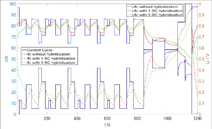
Fig. 2 presents current and voltage profiles obtained along one cycle, more precisely the load current, the FC
current and the FC potential difference in the three configurations investigated (FC alone, FC hybridized with one or three SCs). When the cell is not hybridized, its current instantaneously corresponds to the load demand. In hybridized configuration, the SCs act as a low-pass filter for the FC electrical response, with a time constant proportional to the SC capacitance. Then, for high load current requirements, the energy is partly supplied by the storage device (IFC < Icycle), and conversely, for low demands the FC provides energy to the load while charging
the SCs (IFC > Icycle). Moreover, if the two hybridization modes are compared, the current delivered by the FC
during high load demands is visibly far lower with three SCs than with only one SC: as expected, increasing the storage device capacitance improves the SC contribution to heavy load requirements. During low load demands, the FC current is conversely higher with three SCs than with one SC, enabling a more powerful charge of the storage device. In brief, SCs introduce a smoothing effect in the cell electrical response, and this effect is amplified by larger capacitances, with a larger time constant associated with the low-pass filtering action of SCs.
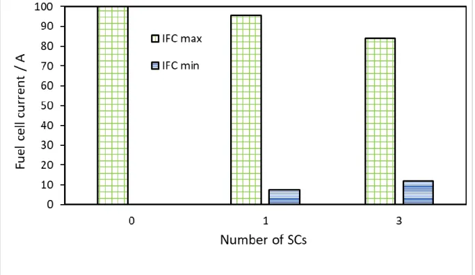
Fig. 3 illustrates the smoothing effect provided by the hybridization. In this figure, both maximum and minimum
currents supplied by the FC during one cycle,
I
FCmaxandI
FCmin respectively, are presented as a function of the number of SCs (0, 1, or 3). The highest value ofI
FCmax, 100 A (related FC current density: 1 A cm-2), is obtained when the FC is used alone. For hybridized configurations, the deviation ofI
FCmaxfrom 100 A corresponds to the current delivered by the SCs. It appears to be approximately three times larger with three SCs than with a single SC. Pertaining toI
FCmin, it can be observed that this current level increases with the number of SCs, from 0 A (FC alone) to nearly 12 A (3 SCs), however without a linear dependence on this number.Besides, it should be noted here that the mean current produced by the FC over one cycle,
I
FCmean, is not affected at steady state by the number of SCs. Indeed,I
FCmean remains constant and equal to the mean load current - at steady state – close to 27.7 A, the mean value of SC current being nil. Accordingly, the filtering effect produced by the SCs tends to smooth the FC current profile toward the mean value of the demand. As a conclusion, a larger number of SCs corresponding to increased capacity of energy storage, allows larger currents to be exchanged to/from the SCs and for longer periods of time, owing to their unique ability to charge and discharge rapidly.3.2. Fuel cell potential difference
As shown in Fig. 3 for currents, Fig. 4 presents both maximum and minimum FC voltages,
U
FCmax andU
FCmin respectively, versus the number of SCs. Generally, as seen in Fig. 2,U
FCmax corresponds to the time periods for which the cell current is equal toI
FCmin. Without SCs, this potential difference is the open-circuit voltage (OCV)7
because
I
FCmin is then equal to zero. On the contrary, in hybridized mode,U
FCmax corresponds to the phase of the cycle for which the cell current is not zero. The maximum FC voltage is shown to decrease with increased SC number, because of the corresponding largerI
FCminvalues. In the same way (see Fig. 2),U
FCmin is recorded for the highest cell current,I
FCmax. For operation of FC alone, this voltage has a very low value, corresponding to 100 A (1 A cm-2) delivered by the cell, but in hybridized mode, this voltage increases as maxFC
I
decreases. Therefore,min FC
U
is further enhanced by higher SC number, because of the larger capacity for energy storage and release allowed by the three SC-stack in the course of the cycle.The variation in the above mentioned FC voltage values expresses the smoothing effect of SCs, as observed above for currents (Section 3.1). Finally, it should be noted that the mean FC voltage over one cycle,
U
FCmean, is nearly unaffected by the increase in the SC number, remaining close to 740 mV.The smoothing effect of SCs on FC electrical response can also be observed in Fig. 2, over one FC_DLC cycle. As a matter of fact, for operation of FC alone, it can be seen that each load current step gives rise to a sharp variation in the cell voltage. However, in the presence of SCs, the above sharp variations are replaced by slow voltage transitions, associated to slow current transients. This smoothing effect is further enhanced by increasing the capacitance of the storage device in hybridized mode. Fig. 2 also puts into evidence the larger time constant involved in the system electrical response, when three SCs are used instead of a single one.
3.3. Mean Power
Fig. 5 shows the mean power supplied by the cell and the hybrid source over one cycle,
P
FCmean andP
HSmeanrespectively, plotted versus the number of SCs. As it can be observed, these powers increase with the SC number.
P
FCmean indeed increases by approximately 12 % if the cell is hybridized with one SC, and by more than 16 % with three SCs, in comparison to the fuel cell alone. In addition, the power generated by the hybrid source is increased by nearly 10 % by changing the number of SCs from 1 to 3. This increase in mean power of either the cell or the hybrid source can be explained by the SC smoothing effect that flattens the profiles of IFC and UFC.For this purpose, these electrical quantities have been expressed as the sum of their average values over one cycle, and their variations around these values over time. For the cell voltage, this leads to Eq. (11):
var FC mean FC FC
U
U
U
(11)and for the cell current to Eq. (12):
var FC mean FC FC
I
I
I
(12)By definition, the mean values of both
U
FCvar andI
FCvarover one cycle are zero in steady state. Then, Eq. (1) can be written by Eq. (13):
T FC FC mean FC mean FC mean FCU
t
I
t
dt
T
I
U
P
0 var var1
(13)8
Because of the cell internal impedance, variations of the cell voltage and of the cell current have opposite signs, therefore the product of
U
FCvar andI
FCvaris negative. As a result, the second hand-right term in Eq.(13) is negative, and its absolute value increases with FC current variations. Consequently, the smoothing effect of SCs tends to increase the FC mean power over one cycle.The same demonstration can be made with the hybrid source. More simply,
P
HSmeancan be expressed versusmean FC
P
and the losses in the wires connecting the cell to the supercapacitors as:2 ,RMS FC w mean FC mean HS
P
R
I
P
(14)Using Eq.(12), the fuel cell RMS current is shown to be an increasing function of the cell current variations:
T FC mean FC RMS FCI
t
dt
T
I
I
0 2 var 2 2 ,1
(15)The second right-hand term in Eq.(15) is positive. It can therefore be deduced that the smoothing effect of the SCs which reduces the variations of the cell current, results in a lower RMS fuel cell current, then in a lower power losses. Finally, it was concluded that
P
HSmean increases with the number of SCs, as a consequence of bothmean FC
P
increase and Plosses decrease.3.4. Hydrogen consumption
Both hydrogen and air flow rates are referred to IFC measured, except for low FC currents for which gas flow
rates are maintained to the safety level current, ISL (20 A here). Moreover, in non-hybridized mode (FC alone),
the gas flow rates are set in advance of few seconds for positive current changes to avoid starvation in positive current changes, which results in higher hydrogen consumption.
Fig. 6 presents the hydrogen flow rate versus time along the cycle, for each hybridization configuration, and Fig. 7 gives the associated hydrogen consumptions. The minimum level of hydrogen consumption appearing in
this graph, equal to 3.86 normal litres (NL) per cycle, corresponds to the mean value of the load current (i.e. 27.7 A), strictly according to Faraday's law (assuming a stoichiometric factor υH2 = 1, ISL = 0 A, and no
anticipated changes in flow rate before positive current steps).
Without hybridization, hydrogen consumption is 5.92 NL per cycle, corresponding to an overconsumption of gas of approximately 53 %. It was intended to differentiate the contributions of each overconsumption factor e.g. H2 over-stoichiometry, minimum H2 flow rate, and anticipation before positive current steps, from the overall hydrogen consumption over one cycle. The 5 s anticipation mode at υH2 = 1.2 and ISL = 20 A, was found to result
in an overconsumption of 0.13 NL per cycle, i.e. about 6 % of the whole H2 overconsumption. The remaining H2 waste (1.93 NL per cycle) is due to the following factors:
(i) H2 stoichiometric factor is 20 % excess (1.2 instead of 1), which leads to the 37 % of H2 overconsumption.
9
(iii) 10 % of H2 overconsumption corresponds to the minimum H2 flow rate (ISL) increased by the 1.2 H2 stoichiometric factor.
When the FC is hybridized with SCs, no flow rate anticipation before positive current steps is needed. Moreover, as mentioned above, the smoothing effect of SCs increases the minimum value of FC current,
I
FCmin, and more generally decreases the gap between the cell current and ISL. This results in a substantial reduction in hydrogenoverconsumption, magnified by the number of SCs. Thereby, hydrogen consumption (calculated by integrating the H2 flow rate over one cycle) is 5.25 NL per cycle when the FC is hybridized with one SC, and 4.99 NL per cycle when three SCs were used in the hybridization, corresponding to an overconsumption of 36 % and 29 %, respectively. The contributions of overconsumption factors are:
(i) With respect to hydrogen's stoichiometric factor 1.2 (instead of 1), the overconsumption of H2 was 56 % with one SC, 68 % with three SCs,
(ii) Corresponding to ISL = 20 A, the overconsumption was 37 % with one SC whereas 27 % with three SCs,
(iii) However, for ISL = 20 A augmented by stoichiometric factor of 1.2, the overconsumption leads to 7 % in
case of one SC and 5 % with three SCs.
The smoothing effect of SCs on FC current is shown in the present work to reduce hydrogen waste associated with the safety level of flow rates. Furthermore, SC contribution is actually an efficient tool to limit the hydrogen waste in cycling mode. Indeed, as direct hybridization naturally protects the PEMFC against fuel starvation, the safety level current has to be lower than the minimum FC current in steady state (ISL <
min FC
I
), provided that the flow controller sensitivity enables such a level. For example, in the case of FC hybridized with three SCs,ISL could be taken at 10 A (0.1 A cm-2), which is approximately two times larger than the sensitivity of the H 2 flow controller used in the test bench. Moreover should
I
FCmin be equal to 12 A, the cycle would be operated without H2 waste due to the flow rate safety level.3.5. Yields
The yield of PEMFC depends on
P
FCmean and the amount of hydrogen required, according to Eq. (5). Likewise, the yield of the hybrid source depends onP
HSmean. As discussed in section 3.3,P
FCmean andP
HSmean increase with SC number, and the amount of hydrogen consumption decreases accordingly, resulting in higher energy yields. For the hybridized systems investigated, YFC is increased by approximately 26 % if the cell is hybridized withone SC, and by 37 % with three SCs, in comparison to the fuel cell alone. In addition, YHS is enhanced by
approx. 16 %, when three SCs are used instead of one (Fig. 8).
It is important to mention here that 1 NL of H2 corresponds to 3.54 Wh: this energy amount was calculated from the enthalpy of the reaction (
H
reaction), as expressed in Eq. (16) on the basis of high heating value (HHV):f O H f O f H reaction
H
H
H
H
2 2 22
1
(16)10
Using the data reported in Fig. 8, the energy yield of the cell alone is 26 %, whereas with three SCs the cell energy yield attains 36 %, corresponding to a significant relative increase (37 %). It has to be kept in mind that the moderate values of the energy yield in comparison to usually expected values for fuel cells running at steady state and for hydrogen stoichiometric factor at 1, are caused by the cycling mode, with the safety conditions considered here. Besides, the gap between YFC and YHS, is due to power losses in the wires. The difference in the
yield is significant in the case of single cell, but it will be reduced in case of hybridized stack of cells as power losses, owing to the wires, would be same with the larger power produced with the stack. Direct hybridization should then be much more beneficial with stacks of cells.
4. Conclusion
The concern of energy storage and the problem of PEMFC throttling has been tackled with its direct hybridization by SCs. This type of association does not require any other device, in particular no additional power electronic converter. In addition, increasing the number of SCs directly hybridized with PEMFC has shown a significant effect on the component contributions and the performance of the system.
On increasing the number of SCs, the performance of the system has increased with a reduced hydrogen demand. As a matter of fact, with increasing the number of SCs, the concern of space, especially in transport applications, still requires to be accounted for in design operations. However, with such combination in cyclic operation, lower energy has to be provided by the PEMFC during high energy demands thanks to the storage capacity of the SCs. Therefore, the rated power of the fuel cell can be reduced, enabling its downsizing in the design of energy conversion systems.
Further points have to be investigated. First, along with the PEMFC, which requires constant temperature and membrane hydration for its effective operation, SCs also have specific requirements, in particular moderate temperature. Secondly, future tests will also consist of optimization of other parameters for the sake of lower hydrogen demand, in particular by reducing the safety level current and by decreasing the H2 over-stoichiometric factor since these changes can enhance the vehicle fuel economy as an advantage of direct hybridization. Finally, the power of the hybrid source has been shown to increase with the increasing number of SCs, because of lower power losses. However, direct hybridization of stack of fuel cells with a stack of SCs as required for transport applications is still in the development phase. Thus, in case of direct hybridization of stack of FCs and SCs, the reduction in power losses would be highly appreciable. But before planning for the stack, it is very important to evaluate the optimum number of SCs required to hybridized. In other words, it is yet to determine the amount of capacitance required for the transport application in case of stack of FCs. But definitely the smoothing effect with larger capacitance has been proven from this paper. Eventually, the cost invested would then be taken into account. Nevertheless, increasing the number of supercapacitors or the capacitance in hybrid automobiles, would not be negative, knowing from the fact the long lifespan of supercapacitors. These are also currently under study.
Acknowledgement
This work was supported partly by the French PIA project «Lorraine Université d’Excellence», reference ANR-15-IDEX-04-LUE for the PhD grant allocated to D. Arora.
11
References
1. Tie S F, Tan C-W (2013) A review of energy sources and energy management system in electric vehicles. Renew. Sustain. Energy Rev. 20:82–102.
2. Janssen LJJ (2007) Hydrogen fuel cells for cars and buses. J Appl Electrochem. 37:1383–1387.
3. Murphy OJ, Cisar A, Clarke E (1998) Low-cost light weight high power density PEM fuel cell stack. Electrochimica Acta. 43:3829–3840. doi:10.1007/s10800-007-9347-8
4. Pukrushpan JT (2004) Control of Fuel Cell Power Systems Principles, Modeling. Springer, London 5. Yuan XZ, Wang H (2008) PEM Fuel Cell Fundamentals. In: Zhang J. (eds) PEM Fuel Cell
Electrocatalysts and Catalyst Layers. Springer, London, pp 1-87
6. Ramani VK, Cooper K, Fenton J M, Kunz H R (2017) Polymer Electrolyte Fuel Cells. In: Breitkopf C., Swider-Lyons K. (eds) Springer Handbook of Electrochemical Energy. Springer Handbooks. Springer, Berlin, Heidelberg.
7. Wahdame B, Girardot L, Hissel D, Harel F, Francois X, Candusso D, et al. (2008) Impact of power converter current ripple on the durability of a fuel cell stack. In: 2008 IEEE International Symposium on Industrial Electronics,1495–500
8. San Martín I, Ursúa A, Sanchis P (2013) Integration of fuel cells and supercapacitors in electrical microgrids: Analysis, modelling and experimental validation. International Journal of Hydrogen Energy. 38:11655–71
9. Thounthong P, Chunkag V, Sethakul P, Davat B, Hinaje M. (2009) Comparative Study of Fuel-Cell Vehicle Hybridization with Battery or Supercapacitor Storage Device. IEEE Transactions on Vehicular Technology. 58:3892–904
10. Ahmed OA, Bleijs JAM. (2015) An overview of DC–DC converter topologies for fuel cell-ultracapacitor hybrid distribution system. Renewable and Sustainable Energy Reviews.42:609–26
11. Morin B, Van Laethem D, Turpin C, Rallières O, Astier S, Jaafar A, et al.(2014) Direct Hybridization Fuel Cell – Ultracapacitors. Fuel Cells.14:500–7
12. Wu B, Parkes MA, Yufit V, De Benedetti L, Veismann S, Wirsching C, et al. (2014) Design and testing of a 9.5 kWe proton exchange membrane fuel cell–supercapacitor passive hybrid system. International Journal of Hydrogen Energy.39:7885–96.
13. Rodatz P, Paganelli G, Sciarretta A, Guzzella L.(2005) Optimal power management of an experimental fuel cell/supercapacitor-powered hybrid vehicle. Control Engineering Practice. 13:41–53.
14. Wu B, Yufit V, Campbell J, Offer GJ, Martinez-Botas RF, Brandon NP. (2013) Simulated and experimental validation of a fuel cell-supercapacitor passive hybrid system for electric vehicles. In: IET Hybrid and Electric Vehicles Conference 2013 (HEVC 2013) pp. 1–6.
15. Gerardin K, Raël S, Bonnet C, Arora D, Lapicque F (2017) Direct Coupling of PEM Fuel Cell to Supercapacitors for Higher Durability and Better Energy Management. Accepted for publication in Fuel Cells.
16. Hinaje M, Raël S, Caron J-P, Davat B (2012) An innovating application of PEM fuel cell: current source controlled by hydrogen supply. International Journal of Hydrogen Energy 37:12481-12488
17. Bonnet C, Lapicque F, Belhadj M, Gerardin K, Raël S, Hinaje M (2017) Can PEM Fuel Cells Experience Appreciable Degradation at Short Circuit? Fuel Cells.17:157–65.
12
18. Tsotridis G, Pilenga A, De Marco G, Malkow T (2015) European Commission, Joint Research Centre. EU harmonised test protocols for PEMFC MEA testing in single cell configuration for automotive applications. Luxembourg: Publications Office. p 38
13
Figure caption
Figure 1: Circuit diagram showing hybridization of PEMFC with SC [15]
Figure 2: Profiles of IFC and UFC in FC_DLC cycle depending on hybridization conditions
Figure 3: Effect of SC number on
I
FCmaxandI
FCminFigure 4: Effect of the SC number on
U
FCmax andU
FCminFigure 5: Effect of the SC number on the mean power and power losses
Figure 6: Effect of the SC number on the hydrogen consumption in FC_DLC mode Figure 7: Effect of number of SCs on the hydrogen consumption over one cycle Figure 8: Effect of the SC number on the yields of the cell and of the hybrid source
14
15
16
Fig. 3 Effect of SC number on
maxFC
17
Fig. 4 Effect of the SC number on
U
FCmax andmin FC
U
18
19
20
21
22
![Fig. 1 Circuit diagram showing hybridization of PEMFC with SC [15].](https://thumb-eu.123doks.com/thumbv2/123doknet/14531765.533774/15.892.84.814.137.561/fig-circuit-diagram-showing-hybridization-pemfc-sc.webp)