HAL Id: hal-01493204
https://hal.archives-ouvertes.fr/hal-01493204
Submitted on 21 Mar 2017
HAL is a multi-disciplinary open access archive for the deposit and dissemination of sci-entific research documents, whether they are pub-lished or not. The documents may come from teaching and research institutions in France or abroad, or from public or private research centers.
L’archive ouverte pluridisciplinaire HAL, est destinée au dépôt et à la diffusion de documents scientifiques de niveau recherche, publiés ou non, émanant des établissements d’enseignement et de recherche français ou étrangers, des laboratoires publics ou privés.
RINGMesh: A programming library for developing
mesh-based geomodeling applications
Jeanne Pellerin, Arnaud Botella, Antoine Mazuyer, Benjamin Chauvin,
François Bonneau, Guillaume Caumon, Bruno Lévy
To cite this version:
Jeanne Pellerin, Arnaud Botella, Antoine Mazuyer, Benjamin Chauvin, François Bonneau, et al.. RINGMesh: A programming library for developing mesh-based geomodeling applications. Computers & Geosciences, Elsevier, 2017, �10.1016/j.cageo.2017.03.005�. �hal-01493204�
RINGMesh: A programming library for developing mesh-based
geomodeling applications
Jeanne Pellerina,∗, Arnaud Botellab,c, Antoine Mazuyerb, Benjamin Chauvinb, Fran¸cois Bonneaub, Guillaume Caumonb, Bruno L´evyc
aWeierstrass Institute - Mohrenstrasse 39 - D-10117 Berlin, Germany
bGeoRessources (UMR 7359), Universit´e de Lorraine-ENSG, TSA 70605, F-54518 Vandoeuvre-l`es-Nancy Cedex, France
cInria - Project Alice, Villers-l`es-Nancy, F-54600, France
Abstract
RINGMesh is a C++ open-source programming library for manipulating discretized geological models. It is designed to ease the development of applications and workflows that use discretized 3D models. It is neither a geomodeler, nor a meshing software. RINGMesh implements functionalities to read discretized surface-based or volumetric structural models and to check their validity. The models can be then exported in various file formats. RINGMesh provides data structures to represent geological structural models, either defined by their discretized boundary surfaces, and/or by discretized volumes. A programming interface allows to develop new geomodeling methods, and to plug in external software. The goal of RINGMesh is to help researchers to focus on the implementation of their specific method rather than on tedious tasks common to many applications. The documented code is open-source and distributed under the modified BSD license. It is available athttps://www.ring-team.org/index.php/software/ringmesh.
Keywords: Structural model, Geology, BRep, Unstructured meshes, C++, Open-source
DOI:10.1016/j.cageo.2017.03.005
∗Corresponding author: MEMA, Universit´e Catholique de Louvain - Avenue Georges Lemaitre 4, bte L4.05.02, 1348 Louvain-la-Neuve, Belgium. Tel.: +32 10472355. Fax: +32 10472999. E-mail address: [email protected]
Email addresses: [email protected] (Arnaud Botella), [email protected] (Antoine Mazuyer), [email protected] (Benjamin Chauvin),
[email protected] (Fran¸cois Bonneau), [email protected] (Guillaume Caumon), [email protected] (Bruno L´evy)
1. Introduction
Subsurface reservoirs often have a complex spatial organization resulting of sedimentary, di-agenetic, magmatic, hydrothermal, and tectonic processes. This motivates the development of flexible geomodeling workflows combining various software and using unstructured grids to com-pute 3D model queries (e.g.Apel,2006;Pouliot et al.,2008), simulate contaminant transport (e.g.
Blessent et al., 2009), flow in abandoned mines (e.g. Collon et al., 2015), flow in fractured rocks (e.g. Paluszny et al., 2007), seismic waves (e.g. Casarotti et al., 2007), joint gravity and seismic inversion (e.g. Lelievre et al., 2012), transient electromagnetism (e.g. Zehner et al., 2015), model CO2 storage (e.g.Park et al.,2014), or magmatic intrusion thermal behavior (e.g.Liu et al.,2012).
Four main types of software may be distinguished:
• Geomodelers create 3D subsurface models from the available observations, generally by build-ing surfaces boundbuild-ing geological objects (seeCaumon et al.(2009)).
• Meshing software create a spatial discretization of modeled objects. They are generally developed for CAD models without considering geological specificities.
• Numerical solvers solve the partial differential equations governing the subsurface physical processes.
• Scientific visualization software focus on performance, usability, and perception. They help geoscientists to interpret and communicate their results.
Whether software choices be motivated by scientific and technological reasons or by more prag-matic reasons (user proficiency, code availability, time, or budget), geoscientists need to adapt to each software specific constraints and vocabulary. This is exemplified by the recurrent develop-ment of file conversion tools, a challenge encountered in all the above cited studies. Beyond this technical challenges of file conversion, communication between software functionalities should also be improved to support new scientific and methodological advances such as a better integration of meshing modules and computational codes (Jackson et al.,2015).
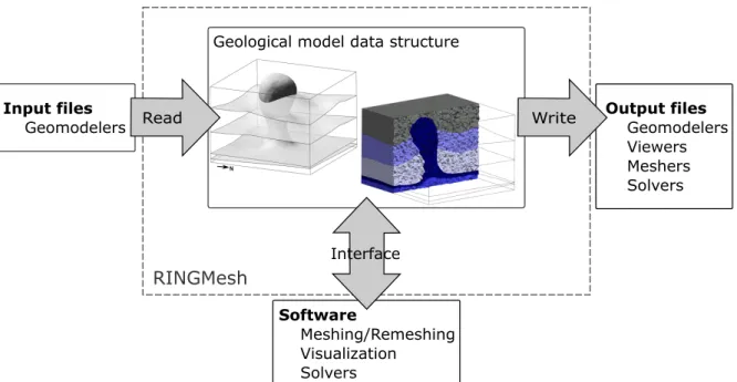
We introduce RINGMesh, an open-source programming library for manipulating discretized geological models, to help the community address these challenges. RINGMesh is neither a geo-modeler, nor a meshing software, nor a solver, nor an extensive visualization software. It is designed (i) to ease the integration of these software in flexible geomodeling workflows and (ii) to be a base for the development of new geomodeling, meshing, solver, and visualization software. From this point of view it is similar to the programming library MLSTK (Garimella, 2004). RINGMesh provides a data structure for discretized 3D structural models and implementations of functional-ities to import, check the validity, make topological and geometrical requests, store attributes on vertices, edges, facets, and cells of the discretization, visualize a model, export the model to solvers (Fig.1). Our objective is to share code which we believe will be useful for researchers working with discretized geological models, preventing the re-implementation of similar codes and gaining time to work on real research goals.
After detailing RINGMesh specifications (Sec. 2), we provide a description of the geological model representation used in RINGMesh in Sec.3. In Section4, we highlight important features of the current implementation (version 3.0). Finally, we show how RINGMesh can be used to import a discretized structural model, check its validity, generate a tetrahedral mesh using Tetgen (Si,
RINGMesh Software Meshing/Remeshing Visualization Solvers Output files Geomodelers Viewers Meshers Solvers Input files Geomodelers
Geological model data structure
Read Write
Interface
Figure 1: RINGMesh 3.0 main features. Supported file formats are listed in Table1.
2. Specifications
RINGMesh is a C++ open-source programming library that implements classes to manipulate 3D geological models.
Inputs. The inputs of RINGMesh are discretized 3D geological models. The models can either be defined by their boundary surfaces (polygonal meshes) or be volumetrically meshed (tetrahe-dra, hexahe(tetrahe-dra, prisms, and pyramids cells). They can be complete structural models built in a geological modeling software to which topological and geological information is attached, or raw discretizations (e.g. .stl ). In that case, topological information is recovered by RINGMesh. The formats supported by RINGMesh 3.0 are given Table 1.
Outputs. RINGMesh 3.0 implements functionalities to check the validity of discretized 3D models, visualize the models, and export them in various file formats. RINGMesh implements a file format converter (see Table 1). For example outputs of Skua-Gocad (Paradigm, 2016) can be converted to Code Aster (EDF,2016) input file format.
Programming Interface. RINGMesh API is designed to be easy to use with well-documented classes and functions, easy to integrate in another software, lightweight and efficient. The most part of the C++ classes, functions, and parameters are documented following the Doxygen standard (Van Heesch,2016).
License and code distribution. The documented code is distributed under the modified BSD license1 and is freely available through the web-based service Bitbucket athttps://bitbucket.org/ring_ team/ringmesh.
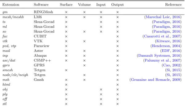
Table 1: Supported file formats for geological models in RINGMesh (version 3.0). All inputs and outputs are discretized models.
Extension Software Surface Volume Input Output Reference
gm RINGMesh × × × ×
mesh/meshb LM6 × × × × (Marechal Loic,2016) ts Skua-Gocad × × × (Paradigm,2016) ml Skua-Gocad × × × (Paradigm,2016) so Skua-Gocad × × × × (Paradigm,2016) fac CUBIT × × (Casarotti et al.,2007)
vtk VTK × × × (Kitware,2016)
pvd, vtp Paraview × × (Henderson,2004)
mail Aster × × × (EDF,2016)
inp Abaqus × × × (Dassault Systemes,2016) asc/dat CSMP++ × × × (Paluszny et al.,2007)
gprs GPRS × × (Cao,2002)
smesh Tetgen × × (Si,2015)
node/ele/neigh Tetgen × × (Si,2015)
msh Gmsh × × × (Geuzaine and Remacle,2009)
html × ×
obj × × ×
ply × × ×
off × × ×
stl × × ×
Platforms. RINGMesh has been compiled on Linux (GCC 4.4 to 4.8) and Windows (Visual Studio 2010 to 2015), for 64 bits platforms only. We provide configuration files using the cross platform configuration tool CMake (CMake,2016).
Dependencies. All dependencies are shipped with RINGMesh. The most important one is the geometric algorithm library Geogram (Levy, 2016) (see also Sec. 4.1). It provides the mesh im-plementation used in RINGMesh, mesh repair functions, search structures, support for various surface and volumetric mesh file formats. We also use zlib (Gailly and Adler,2016) for in-memory compression and decompression of the input and output files.
3. Geological models in RINGMesh
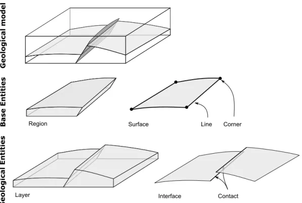
In geomodeling and in computer aided design (CAD), 3D models can be defined using a Bound-ary Representation (BRep): each volume (or region) is bounded by a set of surfaces, each surface is bounded by a set of lines, and each line is bounded by two end points. In RINGMesh, we adopted a simple representation similar to the one used in Gmsh (Geuzaine and Remacle,2009). A geological model is built as sets of entities. The base entities define completely the topology and geometry of the model, while the geological entities define its geological features (Fig. 2). Several alternative computer representations for such models have been proposed in the literature, see for instance
Caumon et al.(2004) and the references therein. 3.1. Topological entities
Base entities. Four base entities constitute the BRep model: Corner (dimension 0), Line (dimension 1), Surface (dimension 2), and Region (dimension 3). Each base topological entity is restricted to be a simply connected manifold of arbitrary genus. Simply connected means that the entity has a
Base Entities
Geological Entities
Region Surface Line Corner
Layer Interface Contact
Geological model
Figure 2: Representation of geological models in RINGMesh: base entities and geological entities.
unique connected component (any two points of the entity can be connected by a path contained in the entity), manifold means that the entity does not contain non-manifold point (for example points at a T intersection). Arbitrary genus means that an entity may have holes and internal boundaries.
Adjacencies in the model are represented with a bi-directional data structure: each entity stores a list of upward adjacencies and a list of downward adjacencies. A specific object, the Universe, stores the extension of the model.
• A Region is bounded by a set of oriented Surfaces.
• A Surface is either closed (no boundary) or bounded by a set of Lines and is incident to one or two Regions.
• A Line is either closed or bounded by one or two Corners (closed Lines are cut at one of their vertices), and is incident to at least one Surface.
• A Corner is incident to at least one Line.
The corresponding data model can be represented graphically by:
Corner 1..n 1 or 2 Line 1..n 0..n S ur f ace 1 or 2 1..n Region
Geological entities. Geological features (faults, horizons, fault-horizon contact, stratigraphic layers, etc.) are represented by geological entities. Each geological entity is a group of base entities to which are associated a name and a geological feature recording its role in the model (normal fault, reverse fault, horizon, unconformity, boundary of the model). In the current implementation of RINGMesh (version 3.0), three geological entities are represented: Contact, Interface, and Layer. Each Contact corresponds to a group of Lines, each Interface to a group of Surfaces, and each Layer to a group of Regions:
Line 0 or 1 1 .. n Contact S ur f ace 0 or 1 1 .. n Inter f ace Region 0 or 1 1 .. n Layer
Adjacency relationships between geological entities are not stored. Contrary to the list of base entities, the number of types of geological entities is not fixed, and new geological entities can be implemented and added to the model. Note that geological entities are not mandatory to define a 3D model in RINGMesh and that non geological-models, or geological models for which geological features are not available, can also be manipulated.
3.2. Geometrical representation
In RINGMesh, the geometry of all base entities is represented by a mesh of the same dimension as the entity. Each Corner corresponds to a 3D position. Each Line is represented by a set of adjacent segments, and each Surface by a polygonal surface mesh. Regions can either be defined by their oriented boundary Surfaces, or by a volumetric mesh. To ensure a correct definition of the model, the geometry of the entities should enforce two conditions: (i) the boundary of each entity is a union of entities of lower dimension and (ii) the intersection of two entities is a union of entities of equal or lower dimension. These conditions are the same than those required to have a Piecewise Linear Complex (PLC), the BRep representation used in Tetgen (Si,2015).
3.3. Validity
Before any manipulation or processing of a discretized geological model, one must be sure that this model is internally consistent. Without this verification, problem identification and debugging of dependent applications is very difficult and cumbersome. Indeed the visual inspection of a 3D model is generally not sufficient to check its validity. The validity of a model is tightly linked to the chosen representation, so validity criteria in RINGMesh are close but not identical to other ones, e.g. Sakkalis et al.(2000).
Base entity validity. Before all, a valid model should be constituted of valid individual entities. First, we check that all model entity discretizations are valid and conformal meshes, i.e. they are defined by a set of elements (vertices, edges, facets, and cells) such that (i) the interior of each element is not empty, and (ii) the intersection of two elements is either empty or is an entity common to their boundaries (Fig. 3c.&d.) (the reader is referred to Frey and George (2000) for complete definitions). Empty elements are typically edges, facets, or cells incident twice to the same
A B C ABC A B C
a. valid triangle b. degenerate triangles
d. intersecting triangle
c. non-conformal triangles
e. non-manifold edge f. non-conformal surfaces Figure 3: Some mesh invalidity configurations.
point (Fig. 3b.). Second, a base entity should not contain any non-manifold point (Fig. 3e.), and should have a unique connected component. Finally, Regions defined by their boundary surfaces are to be tight closed volumes.
Model validity. First, a geological model must have a finite extension, i.e. the region defining the exterior of the model must be tight and closed. Second, the boundary of a model entity can only be a set of entities of the model. All the vertices, edges, or facets on the boundary of a Line, Surface, or Region have to be part of a Corner, Line, or Surface. The third validity condition ensures the consistency of the stored entity adjacencies with the geometrical representation: two distinct entities should intersect exclusively along entities of their common boundary. This implies that there is no intersection between two entities except at points that are on their (geometric) boundaries and that are part of a (topological) entity in their boundary.
Geological validity. To have a valid geological model (or Sealed Geological Model),Caumon et al.
(2004) propose two additional conditions. The first states that only fault or fracture surfaces might end in a volumetric region and not on another surface of the model. The second condition states that two distinct stratigraphic interfaces cannot cross one another.
The above validity checks are implemented in RINGMesh and permit to ensure that a geological model representation verifies expected properties (see filegeo_model_validity.h).
Mesh corrections. Corrective functions are implemented to fix small defects of the mesh and re-move: duplicated vertices/edges/facets, isolated vertices, degenerate edges/facets. These func-tions are adapted and modified from Geogram (Levy, 2016) to allow the duplication of nodes, edges and faces on either sides of geological discontinuities such as fractures and faults (see file geo_model_repair.h). The identification of colocated points involves an epsilon tolerance, while the removal of topological entities is purely combinatorial. Note that in RINGMesh 3.0, there is no complete correction of the BREP representation. The implemented corrections are a subset of those proposed byAlleaume(2009) for CAD models.
0 0 0.5 0.2 1.1 0.110.240.560.980.55 Vertex coordinates (2 values per vertex)
Facet corners (vertex indices)
0 1 2 4 3 3 1 0 1 3 4 2 0 3 7
Facets (begin and end of each facet)
0 1
0 1 2 3 4
0 1
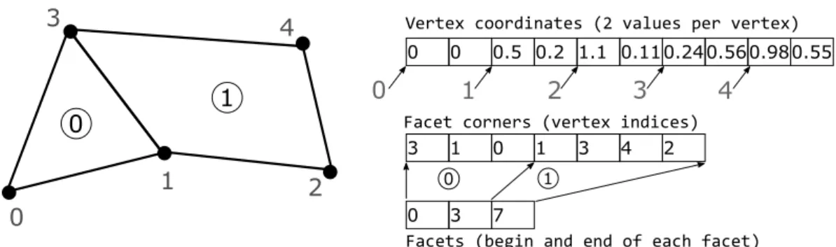
Figure 4: 2D example of storage of an unstructured polygonal mesh in 3 arrays.
4. Current implementation highlights
In this section, we shortly describe the core C++ classes of RINGMesh, version 3.0. The code documentation2 provides additional details on all algorithms and classes to the interested developers.
4.1. Geogram
To minimize maintenance and capitalize on existing advanced capabilities, RINGMesh uses the mesh data structure implemented in the programming library Geogram (Levy,2016), distributed under the modified BSD license3.
Geogram, and therefore RINGMesh, supports polygonal surface meshes and mixed-cell vol-umetric meshes (tetrahedron, hexahedron, triangular prism, and square pyramid). Meshes are represented with an element-node data structure, which is implemented as sets of arrays contigu-ous in memory. Array means the C++ STL std::vector<> class. Each Mesh has an array of vertices whose coordinates are stored contiguously in memory as an array of double. Polygonal surface facets are encoded by two arrays of indices. The first stores contiguously the indices of vertices of all facets, the second gives the indices of the first and last vertex of each facet in the first array (Fig.4). Cell encoding is similar to facet encoding: a first array stores the indices of the vertices of all cells, and a second array stores the indices of the first and last corner of each cell.
Using arrays has clear advantages: the code is easy to understand and to maintain, memory usage is minimal, parallelization is easier, objects can be copied using the low level memory copy function memcpy(), they can be loaded (saved) using fread() (fwrite()), and displayed efficiently with a small number of OpenGL instructions. Finally, attributes on the mesh vertices, edges, facets, or cells are simply additional arrays. However as shown byGarimella(2002), the cost of basic mesh modification operations with such a representation is high. In Geogram, to efficiently modify the mesh, these operations are considered at the mesh level and not at the element level, and are applied to a collection of elements and use in place permutation.
4.2. Geological model implementation
In this section, we briefly introduce the C++ classes implementing the geological model repre-sentation in the version 3.0 of RINGMesh (see Sec. 3).
2http://www.ring-team.org/ring_dl/public/software/ringmesh/doc/
3Several libraries bundled in Geogram have more restrictive licenses: http://alice.loria.fr/software/
To each geological model corresponds an instance of the class GeoModel. A GeoModel stores and manages an array of its constitutive entities. All the entities of the model are instance of the GeoModelEntity class, which store basic identification information and a geological feature. The base entities are implemented as classes (Corners, Lines, Surfaces, Regions) derived from the abstract classGeoModelMeshEntity and store their geometrical (mesh) and topological information (adjacencies and incidences). The abstract base class GeoModelGeologicalEntity is derived to implement the concrete geological entity classes (Contact, Interface, Layer).
Input and outputs are handled by the GeoModelIOHandler. Several classes are implemented to modify and/or create GeoModels: the GeoModelEditor and the GeoModelBuilder, which is derived for the different types of supported inputs. A specific one is dedicated to model repairing, GeoModelRepair.
All base entities (Corner, Line, Surface, Region) of theGeoModel are discretized. Their geometry is defined by an unstructured mesh that is stored as a Mesh object. The Mesh class is a wrapper of the classMesh of Geogram on which the most part of the Geogram functionalities can be used. We also use a global Mesh instance of the whole model which is shared by all entities. This representation is very useful for validity checks, exports to exotic formats, and the recovery of the topology of a set of disconnected conformal surfaces. These operations depend on a consistent global indexing of colocated vertices, edges, and facets of the model (see the implementation of GeoModelBuilderSurface and of is_geomodel_valid()).
4.3. Indexing of mesh elements
As we have seen in Section 4.1, meshes in RINGMesh are represented using an element based strategy that uses arrays of integers to represent the edges, facets, and cells of a mesh. Con-sequently, manipulating meshes, importing discretized geological models from files, representing meshed geological models, and exporting them means dealing with a lot of indexes. Indeed, re-quirements on stored information vary a lot between file formats. For example, to export a model to the solver CSMP++ (Paluszny et al.,2007), a numbering is required for each type of cell (tetra-hedron, prisms, hexa(tetra-hedron, etc) and in each region of the model. To handle this requirement, the elements of the globalMesh of the whole model are reordered and permuted in-place. Cells are sorted region by region, and type by type in each region.
5. Using RINGMesh
With RINGMesh 3.0 it is possible for various input file formats (see Table 1) to: • visualize the model and its discretization (Fig. 5and 6),
• export the model to another file format (Table 1), • recover the volumetric regions of a surface model,
• check the validity of a model and repair small discretization defects (Section 5.1), • call an external software to tetrahedralize the model (Sec. 5.2)
Table 2: Execution timings in seconds for typical tasks performed by RINGMesh 3.0 on a laptop with a 4,00Go RAM, and an Intel i5-4200U processor (2 cores, 1.60GHz). They depend mainly on the total size of the surface and volumetric meshes. The geological models are part of the RINGMesh test dataset and are freely available.
Action Dataset File formats Mesh size Load Validity Facet Int. Action Save In Out # facets/cells (s) check (s) check (s) (s) (s)
Repair annot .ml .ml 130,417 1.33 0.41 4.67 0.79 1.83
Tetgen corbi .ml .gm 277,113 2.36 0.72 4.39 50.42 14.00
Construct modelA6 .mesh .gm 55,426 0.42 0.21 1.46 0.15 1.00
Convert modelA4 .so .gm 34,540 1.24 0.29 0.32 0 1.42
a. b.
Figure 5: Unstructured surface and volumetric meshes of the Corbieres geological model visualized with RINGMesh light viewer. a. Surface model (from Caumon et al.(2009)). b. Tetrahedral mesh generated in RINGMesh using Tetgen (Si,2015).
Tetrahedra
Pyramids
Hexahedra Prisms
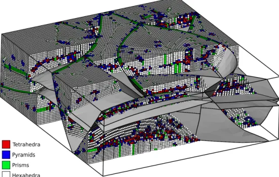
Figure 6: Mixed element volumetric mesh in RINGMesh. The mesh was generated in an application developed on top of RINGMesh byBotella et al.(2016). The model is courtesy of Total.
5.1. Model validity checking
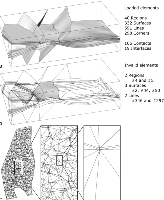
For most geological models, checking by hand the validity of the 3D model topological and geometrical entities is impossible. For example, the model of the Annot sandstones built bySalles et al.(2011) in Skua-Gocad (Fig.7a.) contains 1,261 base entities and 125 geological entities. The model is visually consistent but a few local mesh issues break its validity (in the sense discussed in Section3.3). Using RINGMesh we detect:
• 5 colocated vertices associated to 1 duplicated facet and 8 degenerate facets on Surface #2, resulting in the invalidity of that surface and of the two adjacent regions.
• 2 degenerate Lines (#346 and #397) containing a unique degenerate edge, (2 pairs of colo-cated vertices) resulting in the invalidity of 2 Surfaces (#44 and #50) each containing a degenerate facet built on this edge.
These degenerate Lines, colocated vertices, degenerate and duplicated facets (Fig.7c.) can be automatically removed, resulting in a valid model.
Listing 1: Example of C++ source code to load the Corbieres geological model in RINGMesh, mesh it with TetGen, and export the resulting mesh.
#i n c l u d e <r i n g m e s h / geomodel / g e o m o d e l . h> #i n c l u d e <r i n g m e s h / geomodel / g e o m o d e l a p i . h> #i n c l u d e <r i n g m e s h / geomodel / g e o m o d e l v a l i d i t y . h> #i n c l u d e <r i n g m e s h / i o / i o . h>
i n t main ( ) {
using namespace RINGMesh ; GeoModel model ; g e o m o d e l l o a d ( ” c o r b i e r e s . ml ” , model ) ; i f ( i s g e o m o d e l v a l i d ( model ) ) { t e t r a h e d r a l i z e ( model , ”TetGen ” ) ; g e o m o d e l s a v e ( model , ” c o r b i e r e s t e t g e n . meshb ” ) ; } e l s e { L o g g e r : : o u t ( ” E r r o r ”)<< ”The l o a d e d model i s i n v a l i d ” ; } return 0 ; }
5.2. Interface to external meshing software
To ease the generation of unstructured meshes of geological models, RINGMesh interfaces external meshing software such as TetGen (Si, 2015) and MG-Tetra4 (George et al., 1991) The
meshes are constrained, meaning that the facets of the triangulated surfaces are a subset of the generated tetrahedron facets. When well paths are associated to the structural model, the generated meshes can also be conformal to their edges. The main function running the example of Figure5
is written in Listing 1. The generated volumetric meshes can be exported to various file formats (Table1). They can also be visualized in the standalone light-weight viewer that is shipped with RINGMesh. The implementation of the viewer relies on the fast graphics provided by Geogram (Sec.4.1), as displaying aGeoModel means displaying a set of meshes (Fig.5).
a. b. Loaded elements 40 Regions 332 Surfaces 591 Lines 298 Corners 106 Contacts 19 Interfaces Invalid elements 2 Regions #4 and #5 3 Surfaces #2, #44, #50 2 Lines #346 and #297 c.
Figure 7: Invalid mesh elements and invalid entities detection on the Annot model. a. The Annot geological model (fromSalles et al.(2011)) loaded in RINGMesh. b. Three surfaces of the model are invalid: Surface #2 contains 8 degenerate facets, Surface #44 and #50 contain 1 degenerate facets. c. Surface #2 mesh seems to be correct but contains 8 invisible degenerate facets in this area.
6. Conclusion
RINGMesh is a joint effort to factorize in a common library a simple and efficient data model and to ease the tedious tasks of reading and writing files describing geological models in various formats. Since the very first version that loaded the surface models of Skua-Gocad (Paradigm,
2016), and computed complexity measures (Pellerin et al., 2015), the code has been evolving toward an increasingly flexible library. The current version is designed for researchers who develop new geomodeling methods and implement their own software. It is easy to integrate in another code and provides a set of fundamental operations on discretized geological models.
RINGMesh has been used for the development of meshing methods dedicated to geological models (Pellerin et al., 2014a,b; Botella et al., 2016) and was integrated in several workflows to: find appropriate boundary conditions in 3D geomechanical restoration (Chauvin et al., 2016), to perform homogenization for seismic wave propagation (Cupillard et al., 2015), and to determine far-field stress conditions from several borehole observations (Mazuyer et al., 2016). In these applications, RINGMesh met its initial objectives. Namely, it provided a geological data structure suitable for the development of research codes for tetrahedral and hex-dominant meshing (Fig. 6) and finite element computations. It also served to quickly exchange data between geomodeling software, meshing software, and computational codes.
RINGMesh is still a rather young programming library and its functionalities and data struc-tures are still being improved and extended. The main limitation of the version 3.0 of RINGMesh is that the data structures have not been been designed to support modifications of the geologi-cal models. This makes the implementation of model modification functionalities complicated. A second limitation is the early stage of development of some functionalities such as exports of some formats and validity checks. These tools are very useful in their present form but improvements and more thorough tests are necessary. Some basic tests are already performed using the continuous integration platform Jenkins5. It is however very challenging to check the validity of all exported files.
There are of course many remaining possibilities to extend and improve RINGMesh in order to increase communication between geomodeling software, meshing software, solvers, and visualization software developed or not for geological application. The main directions for future developments of RINGMesh are:
• to support in input and output all widely used file formats in geological modeling, including the open, non-proprietary data exchange format RESQML (Energistics,2016),
• to check modes against different sets of validity conditions,
• to support model modifications, both topological (e.g. removal/addition of a layer, a fault) and on the meshes (e.g. remesh locally a region),
• to repair invalid models.
RINGMesh is open-source and all participations to the project are very welcome. New developments (import/export functions, bug fixes) can be submitted and easily integrated through the project Bitbucket public repository6.
5https://jenkins-ci.org
Acknowledgments
This work has been funded by the RING Consortium7 (A. Botella, A. Mazuyer, F. Bonneau, B. Chauvin), Total S.A. (J. Pellerin, A. Mazuyer), and Chevron (B. Chauvin). The models used in this paper were built with SKUA-GOCAD distributed by Paradigm, which is acknowledged for providing licenses.
References
Alleaume, A., 2009. Automatic non-manifold topology recovery and geometry noise removal. In: Clark, B. W. (Ed.), Proceedings of the 18th International Meshing Roundtable. Springer, pp. 267–279.
Apel, M., Mar. 2006. From 3d geomodelling systems towards 3d geoscience information systems: Data model, query functionality, and data management. Computers & Geosciences 32 (2), 222–229.
Blessent, D., Therrien, R., MacQuarrie, K., Sep. 2009. Coupling geological and numerical models to simulate ground-water flow and contaminant transport in fractured media. Computers & Geosciences 35 (9), 1897–1906.
Botella, A., L´evy, B., Caumon, G., Apr. 2016. Indirect unstructured hex-dominant mesh generation using tetrahedra recombination. Computational Geosciences 20 (3), 437–451.
Cao, H., 2002. Development of techniques for general purpose simulators. Ph.D. thesis, Stanford University, 202 pp. Casarotti, E., Stupazzini, M., Lee, S. J., Komatitsch, D., Piersanti, A., Tromp, J., 2007. CUBIT and Seismic Wave Propagation Based Upon the Spectral-Element Method: An Advanced Unstructured Mesher for Complex 3D Geological Media. In: Brewer, M. L., Marcum, D. (Eds.), Proceedings of the 16th International Meshing Roundtable. Springer, Berlin, Heidelberg, pp. 579–597.
Caumon, G., Collon-Drouaillet, P., Le Carlier de Veslud, C., Sausse, J., Viseur, S., 2009. Surface-based 3D modeling of geological structures. Mathematical Geosciences 41 (9), 927–945.
Caumon, G., Lepage, F., Sword, C., Mallet, J.-L., 2004. Building and Editing a Sealed Geological Model. Mathe-matical Geology 36 (4), 405–424.
Chauvin, B., Stockmeyer, J., Shaw, J. H., Plesch, A., Herbert, J., Lovely, P. J., Guzofski, C. A., Caumon, G., June 2016. Defining proper boundary conditions in 3-d structural restoration: A case study restoring a 3-d forward model of suprasalt extensional structures. In: AAPG Annual Convention and Exhibition. AAPG.
CMake, 2016. CMake. Last date of access 2016-10-12. URLhttps://cmake.org/
Collon, P., Steckiewicz-Laurent, W., Pellerin, J., Laurent, G., Caumon, G., Reichart, G., Vaute, L., Apr. 2015. 3D geomodelling combining implicit surfaces and Voronoi-based remeshing: A case study in the Lorraine Coal Basin (France). Computers & Geosciences 77, 29–43.
Cupillard, P., Botella, A., Capdeville, Y., 2015. Homogenization of 3d geological models for seismic wave propagation. In: SEG Technical Program Expanded Abstracts. pp. pp. 3656–3660.
Dassault Systemes, 2016. ABAQUS. Last date of access 2016-10-18.
URLhttp://www.3ds.com/products-services/simulia/products/abaqus/
EDF, 2016. Code Aster. Last date of access 2016-10-18. URLhttp://www.code-aster.org/V2/spip.php?rubrique2
Energistics, 2016. RESQML. Last date of access 2019-10-18.
URLhttp://www.energistics.org/reservoir/resqml-standards
Frey, P. J., George, P. L., 2000. Mesh generation: application to finite elements. Hermes Science, Oxford. Gailly, J.-L., Adler, M., 2016. Zlib. Last date of access 2016-10-12.
URLhttp://www.zlib.net/
Garimella, R. V., Oct. 2002. Mesh data structure selection for mesh generation and FEA applications. International Journal for Numerical Methods in Engineering 55 (4), 451–478.
Garimella, R. V., 2004. MSTK: A Flexible infrastructure library for developing mesh-based applications. In: Pro-ceedings of the 13th International Meshing Roundtable, Williamsburg, VA. pp. 203–212.
George, P. L., Hecht, F., Saltel, E., 1991. Automatic mesh generator with specified boundary. Computer methods in applied mechanics and engineering 92 (3), 269–288.
Geuzaine, C., Remacle, J.-F., 2009. Gmsh: A 3D finite element mesh generator with built-in pre-and post-processing facilities. International Journal for Numerical Methods in Engineering 79 (11), 1309–1331, last date of access 2016-10-18.
URLhttp://gmsh.info/
Henderson, A., 2004. The ParaView Guide: A Parallel Visualization Application. Kitware, Clifton Park, NY, last date of access 2016-10-12.
URLhttp://www.paraview.org/
Jackson, M., Percival, J., Mostaghimi, P., Tollit, B., Pavlidis, D., Pain, C., Gomes, J., Elsheikh, A. H., Salinas, P., Muggeridge, A., Blunt, M., May 2015. Reservoir Modeling for Flow Simulation by Use of Surfaces, Adaptive Unstructured Meshes, and an Overlapping-Control-Volume Finite-Element Method. SPE Reservoir Evaluation & Engineering 18 (02), 115–132.
Kitware, 2016. Visualization Toolkit. Last date of access 2016-10-12. URLhttp://www.vtk.org/
Lelievre, P. G., Farquharson, C. G., Hurich, C. A., Feb. 2012. Joint inversion of seismic traveltimes and gravity data on unstructured grids with application to mineral exploration. Geophysics 77 (1), K1–K15.
Levy, B., 2016. Geogram. Last date of access 2016-10-18. URLhttp://alice.loria.fr/software/geogram
Liu, L., Zhao, Y., Sun, T., Mar. 2012. 3D computational shape- and cooling process-modeling of magmatic intrusion and its implication for genesis and exploration of intrusion-related ore deposits: An example from the Yueshan intrusion in Anqing, China. Tectonophysics 526–529 (0), 110–123.
Marechal Loic, 2016. LibMesh. Last date of access 2016-10-18. URLhttps://github.com/LoicMarechal/libMeshb
Mazuyer, A., Giot, R., Cupillard, P., Conin, M., Thore, P., 2016. Stress estimation in reservoirs by a stochastic inverse approach. In: 7th International Symposium on In-Situ Rock Stress. International Society for Rock Mechanics, pp. 362–368.
Paluszny, A., Matthai, S. K., Hohmeyer, M., May 2007. Hybrid finite element-finite volume discretization of complex geologic structures and a new simulation workflow demonstrated on fractured rocks. Geofluids 7 (2), 186–208. Paradigm, 2016. SKUA-GOCAD. Last date of access 2016-10-18.
URLhttp://www.pdgm.com/products/skua-gocad/
Park, C.-H., Shinn, Y., Park, Y.-C., Huh, D.-G., Lee, S., Jan. 2014. PET2ogs: Algorithms to link the static model of Petrel with the dynamic model of OpenGeoSys. Computers & Geosciences 62, 95–102.
Pellerin, J., Caumon, G., Julio, C., Mejia-Herrera, P., Botella, A., 2015. Elements for measuring the complexity of 3D structural models: Connectivity and geometry. Computers & Geosciences 76 (0), 130 – 140.
Pellerin, J., L´evy, B., Caumon, G., 2014a. Toward Mixed-element Meshing based on Restricted Voronoi Diagrams. Procedia Engineering 82 (0), 279 – 290, 23rd International Meshing Roundtable (IMR23).
Pellerin, J., L´evy, B., Caumon, G., Botella, A., 2014b. Automatic surface remeshing of 3D structural models at specified resolution: A method based on Voronoi diagrams. Computers & Geosciences 62 (0), 103 – 116.
Pouliot, J., B´edard, K., Kirkwood, D., Lachance, B., May 2008. Reasoning about geological space: Coupling 3D GeoModels and topological queries as an aid to spatial data selection. Computers & Geosciences 34 (5), 529–541. Sakkalis, T., Shen, G., Patrikalakis, N., Oct. 2000. Representational validity of boundary representation models.
Computer-Aided Design 32 (12), 719–726.
Salles, L., Ford, M., Joseph, P., De Veslud, C., Le Solleuz, A., 2011. Migration of a synclinal depocentre from turbidite growth strata: the Annot syncline, SE France. Bulletin de la Soci´ete G´eologique de France 182 (3), 199–220. Si, H., Feb. 2015. TetGen, a Delaunay-Based Quality Tetrahedral Mesh Generator. ACM Transactions on
Mathe-matical Software 41 (2), 1–36, last date of access 2016-10-12. URLhttp://wias-berlin.de/software/tetgen/
Van Heesch, D., 2016. Doxygen. Last date of access 2016-10-12. URLhttp://www.doxygen.org
Zehner, B., B¨orner, J. H., G¨orz, I., Spitzer, K., Jun. 2015. Workflows for generating tetrahedral meshes for finite element simulations on complex geological structures. Computers & Geosciences 79, 105–117.