HAL Id: hal-01627711
https://hal.archives-ouvertes.fr/hal-01627711
Submitted on 2 Nov 2017
HAL is a multi-disciplinary open access
archive for the deposit and dissemination of
sci-entific research documents, whether they are
pub-lished or not. The documents may come from
teaching and research institutions in France or
abroad, or from public or private research centers.
L’archive ouverte pluridisciplinaire HAL, est
destinée au dépôt et à la diffusion de documents
scientifiques de niveau recherche, publiés ou non,
émanant des établissements d’enseignement et de
recherche français ou étrangers, des laboratoires
publics ou privés.
Towards a smart camera for monocular SLAM
Abiel Aguilar-González, Miguel Arias-Estrada
To cite this version:
Abiel Aguilar-González, Miguel Arias-Estrada. Towards a smart camera for monocular SLAM. ICDSC
’16 10th International Conference on Distributed Smart Camera, Sep 2016, Paris, France. pp.128
-135, �10.1145/2967413.2967441�. �hal-01627711�
Towards a smart camera for monocular SLAM
Abiel Aguilar-González and Miguel Arias-Estrada
Instituto Nacional de Astrofísica, Óptica y Electrónica Luis Enrique Erro # 1, Tonantzintla, Puebla, México C.P. 72840
{abiel,ariasmo}@inaoep.mx
ABSTRACT
In recent years the interest on monocular-SLAM (Simultaneous Localization and Mapping) has increased, this because nowadays it is possible to find inexpensive, small and light commercial cameras and they provide visual environmental information that can be exploited to create 3D maps and camera pose in an unknown environment. A smart camera that could deliver monocular-SLAM is highly desirable, since it can be the basis of several robotics/drone applications. In this article, we present a new SLAM framework that is robust enough for indoor/outdoor SLAM applications, and at the same time is parallelizable in the context of FPGA architecture design. We introduce new feature-extraction/feature-matching algorithms, suitable for FPGA implementation. We propose an FPGA based sensor-processor architecture where most of the visual processing is carried out in a parallel architecture, and the 3D map construction and camera pose estimation in the processor of a SoC FPGA. An FPGA architecture is lay down and hardware/software partition is discussed. We show that the proposed sensor-processor can deliver high performance under several indoor/outdoor scenarios.
CCS Concepts
• Computer systems organization ➝ System on a chip.
Keywords
SLAM; SoC; FPGA
1. INTRODUCTION
Smart cameras integrate processing close to the image sensor, so they can deliver high level information to a host computer/robot or high level decision process. Progress in microprocessor power and FPGA technology makes feasible to build compact and low cost smart cameras, but the actual problem is how to program them efficiently given the wide variety of algorithms and the custom approach to have a smart camera for a specific application, i.e., for a smart video surveillance the camera could be detecting and tracking pedestrians, but for a robotic camera, the accelerated processing in the camera could be edge and feature detection. Commercially some approaches simply offer a path to recompile an application developed in OpenCV [1] or any other programming environment, into an embedded processor, compact x86 compatible processor or DSP processor [2-3]. Some companies offer a dedicated IP framework coupled with vision processors that accelerate a subset of vision algorithms, mainly motivated by automotive industry trends in visual assistance and a path for self-guided vehicles technology [33].
A recent trend is the integration of GPU embedded processors in platforms that already support a subset of OpenCV like the Jetson TK1 and XT1 boards [4-5]. Nevertheless, an FPGA based smart camera offer advantages from all the previous approaches: possibility to design parallel architectures that accelerate processing time, integration of hardware-software architectures with the SoC FPGAs, low power consumption for embedded applications and lower cost than GPU based embedded solutions. The inconvenient to develop an FPGA smart camera is the lack of standards to reuse FPGA components, lack of internal standard or architecture to facilitate the hardware/software co-processing and effective use of memory transfers between all the submodules in the vision processing pipeline. The latest is being addressed with high level languages and component reuse similar to what is done in software. In particular, solutions like CAPH [6], GPstudio [7] or OpenCL libraries [8] and vision pipeline standards like OpenVX [9] are paving the road to a standard that can help build more sophisticated vision processing pipelines.
1.1 Monocular-SLAM in a smart camera
Several SLAM solutions such as, EKF-based, graph-based and visual-based solutions are available in the literature. However, the recent trend is for visual-based solutions, more specifically, monocular-SLAM (visual-SLAM with a single camera), since it can provides visual information such as texture and color from the scene and requires lowest power and cost than other visual-SLAM formulations (stereo-based or RGBD-based solutions) [10]. The basis of monocular-SLAM is that a single moving camera, can obtain 3D information of the environment and deliver a rough 3D map that can include texture and color of the elements within the map. This is highly used in robotics or autonomous vehicle applications since it is possible to navigate and at the same time reconstruct in 3D the robot/vehicle positions and the position of objects, obstacles, walls, etc., in its surroundings [11-12]. Having a smart camera that delivers monocular-SLAM can open several research lines and applications, since at a higher level it will be possible to integrate cooperative information from several cameras, integrate other image understanding algorithms and have a better visual representation of the world. Smart cameras with monocular-SLAM would be useful in autonomous vehicles, drones and mobile robotics, leveraging the central processors of those platforms for the high computational cost of the control and navigation tasks. The preferred choice for an FPGA-based smart camera is to integrate low level image preprocessing tasks and deliver the results to a software processor that performs high level processing tasks. This approach has proved successful in the past [13-14], and it is what we will follow. In previous work only the feature-extractor/feature-matching algorithm was implemented in the FPGA, while the rest of the data processing is carried on in a conventional processor. In our case we explore further integration of monocular-SLAM formulation into the FPGA accelerated architecture.
1.2 Related work
Since the last decade, published articles reflect a tendency for using vision as the only external sensorial perception system to solve the SLAM problem [15-17]. In some cases, algorithms were formulated in the context of a sensor or smart camera. Authors of [18] introduced an embedded vision sensor based on reconfigurable hardware (FPGA) to perform stereo image processing and 3D mapping for sparse features. It was proposed an EKF based visual SLAM. The system uses vision as the only source of information and achieves a convenient performance for small industrial environments. Unfortunately, the approach is limited to sparse 3D maps and, the stereo configuration introduces some inconvenient due to the cameras synchronization and mechanical alignment. In [19] a visual-inertial sensor unit for robust SLAM capabilities is presented. Four cameras are interfaced through an ARM/FPGA design, an Inertial Measurement Unit (IMU) provides gyro and accelerometer measurements. The proposed approach delivers a convenient fusion of visual and inertial cues with a level of robustness and accuracy difficult to achieve with purely visual-SLAM systems. The main limitation of the approach is that only the feature extraction algorithm was accelerated in the FPGA, this represents an inefficient hardware/software partition since other tasks such as, feature-matching can be accelerated in the FPGA.
In [20], the architecture and the processing pipeline of a smart camera suited for real time applications is discussed. The authors proposed a memoryless computing architecture based on low cost FPGA devices. It was proposed a stereo matching approach with sub-pixel accuracy. Finally, the results are delivered via USB2.0 front end. The developed sensor allows to infer, dense and accurate depth maps under indoor/outdoor environments. The developed camera was used in a SLAM application, nevertheless, all the SLAM process is carried out in a CPU implementation. This limits the performance for robotics mobile applications in which compact systems with low power consumption are required. In [21] a smart camera for a real-time gesture recognition system was presented. The smart camera was designed and implemented in a System-on-a-Chip (SoC) device, using reconfigurable computing technology. In this system, the gesture images are captured by a CMOS digital camera. After some preprocessing steps, images are sent to a Fault Tolerant Module (FTM) for the actual recognition process. The FTM implements a RAM-based neural network, using three knowledge bases. A real-world application was presented, it consists of four smart cameras used in SLAM tasks for robotic navigation. The proposed system aims to increase the accuracy of the maps generated by the SLAM algorithm by using images taken from the robot perimeter. Unfortunately, the algorithm is limited to landmarks, and the 3D maps are sparse maps that limits the environmental understanding.
2. THE PROPOSED ALGORITHM
In this work, we are interested in a smart camera that delivers a SLAM solution without post-processing steps and that allows a relatively simple and compact system design. In Fig. 1 an overview of our algorithm is shown. We accelerate the feature extraction and feature matching in hardware while the camera matrix/camera pose estimation and 3D estimation are implemented in software. The hardware/software partition is based on what parts of the algorithm can be parallelized, but also targeting that the software part can be executed in real-time in a processor in a SoC FPGA device. Therefore, the software computational load must be low.
Figure 1: The proposed algorithm
2.1 Feature extraction
Several feature extraction algorithm have been reported in the literature, nevertheless, in most cases, performance for FPGA implementation is limited. In this work, we present a new feature extraction algorithm that uses the maximum Eigenvalues as corner metric response. This algorithm is robust enough to detect feature points under any types of input images and enables efficient FPGA implementation. Considering 𝐼 as a grayscale image, first, we propose to compute the 𝑥, y gradients as shown in Eq. 1 and 2, respectively.
𝐺𝑥(𝑖, 𝑗) = (𝐼(𝑖 − 1, 𝑗)) − (𝐼(𝑖 + 1, 𝑗)) (1)
𝐺𝑦(𝑖, 𝑗) = (𝐼(𝑖, 𝑗 − 1)) − (𝐼(𝑖, 𝑗 + 1)) (2)
We define the 𝐴, 𝐵, 𝐶 matrixes as 𝐴(𝑖, 𝑗) = 𝐺𝑥(𝑖, 𝑗) ∙ 𝐺𝑥(𝑖, 𝑗),
𝐵(𝑖, 𝑗) = 𝐺𝑦(𝑖, 𝑗) ∙ 𝐺𝑦(𝑖, 𝑗) and 𝐶 (𝑖, 𝑗) = 𝐴(𝑖, 𝑗) ∙ 𝐵(𝑖, 𝑗). Once the
𝐴, 𝐵, 𝐶 matrixes are computed, they have to be convolved with an appropriate Gaussian kernel. In [22] we presented an image convolution framework that allows flexible 2D convolution and at the same time high performance for FPGA implementation. Based on our algorithm presented in [22], we proposed a convolution kernel as shown in Eq. 3. Then, we convolve the 𝐴, 𝐵, 𝐶 matrixes as following: 𝐴 = 𝐴 ∗ 𝑀, 𝐵 = 𝐵 ∗ 𝑀, 𝐶 = 𝐶 ∗ 𝑀, where the operator ∗ represents the 2D spatial convolution between an image 𝐼 and convolution kernel 𝑀. For more details see [22].
𝑀 = [ 0 0 1 128 0 0 0 1 128 1 64 1 128 0 1 128 1 64 1 8 1 64 1 128 0 1 128 1 64 1 128 0 0 0 1 128 0 0 ] 𝑀 = [ 20 20 20 20 20 27 20 20 20 20 20 20 20 27 20 26 20 27 20 20 20 27 20 26 20 23 20 26 20 27 20 20 20 27 20 26 20 27 20 20 20 20 20 20 20 27 20 20 20 20] (3)
Original kernel Convolution kernel using our algorithm [22]
In order to detect feature points form an image, we proposed Eq. 4 as corner response metric, where 𝐴, 𝐵, 𝐶 are the convolved matrices and the operator 𝑓{𝑔} is defined as shown in Eq. 5, where 𝐶𝑛, 𝐶′𝑛 are constant values for a LUT-based square root
function [23]. In this case, LUT-based functions can be used for hardware implementation for complex operations such as, square roots, Euler function, etc., with low hardware consumption and real-time processing.
𝑅𝑒𝑠𝑝𝑜𝑛𝑠𝑒(𝑖, 𝑗) = (𝐴(𝑖, 𝑗) + 𝐵(𝑖, 𝑗)) − 𝑓{(𝐴(𝑖, 𝑗) − 𝐵(𝑖, 𝑗)).2
+ 4𝐶.2}
𝑓{𝑔} = { 𝐶1, 𝑖𝑓 𝑔 ≤ 𝐶′1 𝐶2, 𝑖𝑓 𝑔 ≤ 𝐶′2 ⋮ 𝐶𝑛, 𝑖𝑓 𝑔 ≤ 𝐶′2 (5)
Finally, we consider that a pixel (𝑖, 𝑗) from an image 𝐼 is a feature point/corner only if 𝑅𝑒𝑠𝑝𝑜𝑛𝑠𝑒(𝑖, 𝑗)satisfy 𝑅𝑒𝑠𝑝𝑜𝑛𝑠𝑒(𝑖, 𝑗) ≥ 𝛼, where 𝛼 is as barrier value provided by the user. For practice, in all our experiments we use a barrier value equal to 25, i.e. 𝛼 = 25.
2.2 Feature matching
Considering 𝐴 as a video sequence of 𝑠 frames, we can apply our feature extraction algorithm (Section 3.1), to obtain 𝑔 initial features defined as 𝑥𝑖(𝑔) = 𝑥, 𝑦𝑖(𝑔) = 𝑦; where 𝑥, 𝑦 are the
spatial position for all extracted points. Then, we propose a new feature matching algorithm that searches for a square region centered in any feature 𝑔 in frame 𝑖 that is similar or equal than a similar size square region in frame 𝑖 + 1, located within a search region in frame 𝑖 + 1. In this scenario, we propose Eq. 6 and 7; where 𝑥𝑖+1(ℎ), 𝑦𝑖+1(ℎ) are the spatial locations for all the
features in frame 𝑖 + 1 and, 𝑖 + 1 satisfy 𝑖 + 1 <= 𝑠. 𝐶 measures the similarity between patches and is defined as shown in Eq. 8, where 𝑟 is the search region size, computed via Eq. 9, considering 𝑋, 𝑌 as the horizontal, vertical resolution of the imager. 𝐼𝑖 and 𝐼𝑖+1 represent the spatial coordinates of pixels for
two different images captured by the imager, and 𝛽, 𝜎 are the spatial location for all the patches in frame i+1, they ranges between –r up to r with increments of 1.
𝑥𝑖+1(ℎ) = ∑ 𝑚𝑖𝑛𝛽𝐶(𝛽, 𝜎) ℎ=𝑔 ℎ=1 (6) 𝑦𝑖+1(ℎ) = ∑ 𝑚𝑖𝑛𝜎𝐶(𝛽, 𝜎) ℎ=𝑔 ℎ=1 (7) 𝐶(𝛽, 𝜎) = ∑ ∑ (𝐼𝑖(𝑥 + 𝑢, 𝑦 + 𝑣) − 𝐼𝑖+1(𝑥 + 𝛽 + 𝑢, 𝑦 𝑣=𝑟 𝑣=−𝑟 𝑢=𝑟 𝑢=−𝑟 + 𝜎 + 𝑣))2 (8) 𝑟 = min{𝑘 ∈ ℤ | √(𝑋/128) 2+ (𝑌/128)2 2 ≤ 𝑘} (9)
2.3 Camera matrix estimation
Given two corresponding point sets: 𝑞 = {(𝑥1, 𝑦1), (𝑥2, 𝑦2) …
(𝑥𝑛, 𝑦𝑛)} and 𝑔 = {(𝑥1, 𝑦1), (𝑥2, 𝑦2) … (𝑥𝑛, 𝑦𝑛)} (these are
obtained by applying our feature matching algorithm), a matrix 𝐴 can be estimated as following:
𝐴 [ 𝑞(𝑥1)∙𝑔(𝑥1) 𝑞(𝑥2)∙𝑔(𝑥2) ⋮ 𝑞(𝑥𝑛)∙𝑔(𝑥𝑛) 𝑞(𝑦1)∙𝑔(𝑥1) 𝑞(𝑦2)∙𝑔(𝑥2) ⋮ 𝑞(𝑦𝑛)∙𝑔(𝑥𝑛) 𝑔(𝑥1) 𝑔(𝑥2) ⋮ 𝑔(𝑥𝑛) 𝑞(𝑥1)∙𝑔(𝑦1) 𝑞(𝑥2)∙𝑔(𝑦2) ⋮ 𝑞(𝑥𝑛)∙𝑔(𝑦𝑛) 𝑔(𝑦1) 𝑞(𝑥1) 𝑞(𝑦1) 1 𝑔(𝑦2) 𝑞(𝑥2) 𝑞(𝑦2) 1 ⋮ ⋮ ⋮ ⋮ 𝑔(𝑦𝑛) 𝑞(𝑥𝑛) 𝑞(𝑦𝑛) 1 ],
let [𝑈 𝑆 𝑉] denote the singular value decomposition (SVD) of 𝐴, then, the fundamental matrix 𝐹 can be computed as following: 𝐹 = 𝑈 ∙ 𝑑𝑖𝑎𝑔([𝐷(1,1) 𝐷(2,2)] 0) ∙ 𝑉′. Then, the
essential matrix 𝐸 can be estimated as 𝐸 = 𝐾′𝐹𝐾, where 𝐾 is the calibration matrix for the imager. Finally, by applied singular value decomposition (SVD) over 𝐸 and solving for a close solution, the camera matrix 𝑃 can be estimated. For more details about camera matrix estimation see [24].
2.4 Linear triangulation
Given two corresponding point sets: 𝑞 = {(𝑥1, 𝑦1), (𝑥2, 𝑦2) …
(𝑥𝑛, 𝑦𝑛)}, 𝑔 = {(𝑥1, 𝑦1), (𝑥2, 𝑦2) … (𝑥𝑛, 𝑦𝑛)} and considering 𝑃1,
𝑃2 as the camera matrix estimated via the Essential matrix and
camera matrix centered at the origin, respectively, we can
compute the following variables: 𝐴1= 𝑞(𝑥1)∙𝑃1(3, 𝑖) − 𝑃1(1, 𝑖),
𝐴2= 𝑞(𝑦1)∙𝑃1(3, 𝑖) − 𝑃1(1, 𝑖), 𝐴3= 𝑞(𝑥1)∙𝑃2(3, 𝑖) − 𝑃2(1, 𝑖), 𝐴3=
𝑞(𝑦1)∙𝑃2(3, 𝑖) − 𝑃2(1, 𝑖), 𝐴[𝐴1 𝐴2 𝐴3 𝐴4]. Finally, let [𝑈 𝑆 𝑉]
denote the singular value decomposition (SVD) over 𝐴, the 3D positions for all the tracked points (the mapping solution of the SLAM process) can be denoted as 𝑉(𝑖, 4). For more details about linear triangulation see [24].
2.5 Camera pose estimation
Given two corresponding point sets: 𝑿 = {𝒙𝟏, 𝒙𝟐… 𝒙𝒏}, 𝒑 =
{𝒑𝟏, 𝒑𝟐… 𝒑𝒏}, the Least Squares algorithm [24] estimates the
translation 𝒕 and rotation 𝑹 that minimizes the sum of the squared re-projection error, as shown in Eq. 10, where 𝒙𝒊 and 𝒑𝒊 are
feature points matching across two different viewpoints captured by the imager. 𝐸(𝑅, 𝑡) =1 𝑁∑ ∥ 𝑥𝑖− 𝑅𝑝𝑖− 𝑡 ∥ 2 𝑁𝑝 𝑖=1 (10)
The algorithm definition assumes that if the correct correspondences between feature points are known, the correct relative rotation/translation can be calculated in closed form. i.e., considering accurate 2D matching (provided by our feature tracking algorithm), the next step is to compute the center of mass on the input sets 𝑋,𝑝 as shown in Eq. 11 and 12.
𝜇𝑥= 1 𝑁𝑥 ∑ 𝑥𝑖 𝑁𝑥 𝑖=1 (11) 𝜇𝑝= 1 𝑁𝑝 ∑ 𝑝𝑖 𝑁𝑝 𝑖=1 (12)
Then, subtract the corresponding center of mass from every point in the input sets, as shown in Eq. 13 and 14.
𝑋′= {𝑥 𝑖− 𝜇𝑖} = {𝑥′𝑖} (13) 𝑃′= {𝑝 𝑖− 𝜇𝑝} = {𝑝′𝑖} (14) Finally, let 𝑊 = ∑ 𝑥′𝑖𝑝′𝑖𝑇 𝑁𝑝
𝑖=1 denote the singular value
decomposition (SVD) of 𝑊, defined as shown in Eq. 15; where 𝑈, 𝑉 are unitary 𝜖ℝ3×3, and 𝜎
1< 𝜎2< 𝜎3 are the singular values
of 𝑊. Using camera geometry, it is possible to define 𝑅 = 𝑈𝑉𝑇.
Thus, If 𝑟𝑎𝑛𝑘(𝑊) = 3, the optimal solution of 𝐸(𝑅, 𝑡) is unique and is given as shown in Eq. 16; where the minimal value of the re-projection function at (𝑅, 𝑡) is computed by Eq. 17. For more details see [24] 𝑊 = 𝑈 [ 𝜎1 0 0 0 𝜎2 0 0 0 𝜎3 ] 𝑉𝑇 (15) 𝑡 = 𝜇𝑥− 𝑅𝜇𝑝 (16) 𝐸(𝑅, 𝑡) = ∑(∥ 𝑥′ 𝑖∥2+∥ 𝑝′𝑖∥ 2) 𝑁𝑝 𝑖=1 − 2(𝜎1+ 𝜎2+ 𝜎3) (17) (17)
Note that in a SLAM system, the camera rotation and orientation computed by the Least Squares algorithm represents the
localization solution of the SLAM process. In practice, the first
camera is located at the origin, and the 𝑅, 𝑡 values represent the second camera localization with respect to the origin (considering feature tracking across frame 1 and 2 from a video sequence captured by the imager). This process must be iterated, i.e., to localize the next camera the Least Squares algorithm requires feature tracking across frames 2 and 3, and then, the third camera localization with respect to the second can be computed.
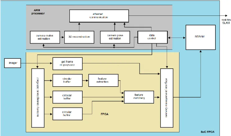
Figure 2: An FPGA-based smart camera for monocular-SLAM
3. FPGA ARCHITECTURE
In Fig. 2 an overview of the proposed hardware-software partition is presented. The architecture is centered on a SoC FPGA where all recursive/parallelizable algorithms are accelerated in the FPGA fabric while non-recursive algorithms are implemented in the embedded processor of the SoC FPGA. In this scenario, feature extraction/matching algorithms are implemented in hardware. Algorithms such as: camera pose estimation and 3D reconstruction are non-parallelizable since they require iterative elements and complex mathematics, then a software implementation is more suitable. In general, the basis of the proposed smart camera is the data control unit (see Fig. 2), this unit operates as process-sequencer, where the image subsections are feed to/from the external SDRAM memory using a DMA; as well as the image read out into the circular buffers used to hold local sections of the image and allow for local parallel access and facilitate parallel processing.
Images from the image sensor are stored in an external SDRAM that holds at least 2 frames from the sequence, and later the SDRAM is read by the FPGA to cache parts of the frames into circular buffers. A memory management interface is responsible for data transfers in segments of the image (usually several rows of pixels) to/from the SDRAM. The core of the FPGA architecture are the circular buffers attached to the local processors that can hold temporarily as cache, the image sections from two frames, and that can deliver parallel data to the processors. Two separate image processing accelerators implemented in parallel-pipeline form address the feature extraction/matching step.
Data results from the FPGA processors (the computed feature correspondences between the two frames) is post-processed by the SoC microprocessor to obtain the camera pose and 3D reconstruction for a pair of frames. Finally the SLAM results are sent to a host computer using the Ethernet communication.
3.1 The circular buffers
Several image processing applications process pixel data from small neighborhoods from an image, and carrying out a calculation at each position of the neighborhood. For processing purposes, the conventional approach is to store the entire input image into a frame buffer, access the neighborhood’s pixels and apply the operation needed to produce the output image. Considering the convolution kernel used in the feature extractor, 25 pixel values are needed to perform the computations each time the kernel is moved and each pixel in the image is read several times. In this case, the memory bandwidth constraints make impossible to obtain all pixels stored in the memory in only one clock cycle, unless any kind of local caching is performed. In [22] we introduced a circular buffer schema in which input data from the previous 𝑁 rows can be stored using the memory buffers till the moment when the neighborhood is scanned along subsequent rows. To reuse hardware resources when new image data is processed, a shift mechanism between buffer rows is used. Data inside the buffer can be accessed in parallel and each input pixel is fed only once to the FPGA device. In this work, we follow a similar approach to achieve high data reuse and high level of parallelism. Then, feature extraction/matching is carried out in modules where all pixels for the convolution kernel and within the search region can be read in parallel.
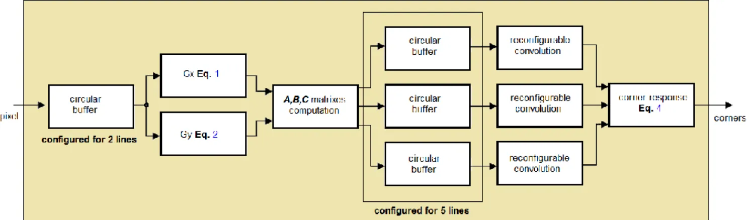
Figure 3: The FPGA architecture for the feature extraction algorithm
3.2 The feature extraction accelerator
In Fig. 3 an overview of the proposed FPGA architecture for the feature extraction accelerator is shown. The main objective is to process all data in stream, this approach has proved successful in the past, allowing real-time processing and compact system design [25-26]. First, the pixels from a frame 𝑖 are stored in a circular buffer that can deliver all pixels centered in 2x2 pixel regions in parallel. Then, the 𝑥, y gradients are computed in parallel. Using the gradients, the 𝐴, 𝐵, 𝐶 matrixes can be computed. Then, the circular buffers can deliver all pixels centered in 5x5 pixel regions in parallel. Using these regions, a 2D spatial convolution can be computed as a stream. In order to achieve high performance for FPGA implementation, we propose the use of reconfigurable convolution units, similar to [22]. Finally, using the convolved images, the Eq. 4 detects the corresponding feature points. Based on the formulation of the
reconfigurable convolution processors [22], any pixel in the output images have to be defined by integer values. This is highly useful since Eq. 4 is formulated with integer operations, reducing the hardware resources required for the implementation.
3.3 The feature matching accelerator
Fig. 4 shows the feature matching accelerator architecture. Similar to the extraction process, this module also delivers all results as a data stream. The module works as follows: first, the pixels from a frame 𝑖 and frame 𝑖 + 1 are stored in a circular buffer that can deliver all pixels centered in size 𝑟2 + 1 × 𝑟2 + 1, where 𝑟 is the search region size. For each feature 𝑞 in frame 𝑖 one square patch of size 𝑟 (which is the size of the search window) centered on the 𝑞 spatial location have to be compared with several square patches in frame 𝑖 + 1. Then, the patch in frame 𝑖 + 1 that minimizes a cost function (Eq. 8) will be the corresponding match with the current location of the feature 𝑞 in frame 𝑖 + 1. For an FPGA implementation, all pixels/patches can be compared in parallel, as illustrated in Fig. 5. Considering that the cost function is the most computational intensive operation, we propose a pixel-parallel/patch-parallel formulation to accelerate the process.
Finally, in order to estimate the current position of a feature 𝑞 (Eq. 6 and 7), a CASE structure allows simple solution of the feature matching problem. i.e., if the cost function response for all 𝛽, 𝜎 values are known, a CASE structure operates as a multiplexer implemented in hardware. This allows to detect the indexes that minimizes the 𝛽, 𝜎 values in simple form (indexes that minimizes the 𝛽, 𝜎 values represent the current position of 𝑞 in frame 𝑖 + 1).
Figure 4: The FPGA architecture for the feature matching algorithm
Figure 5: Parallel-pipeline implementation of the proposed feature matching algorithm.
4. RESULTS
In this section preliminary results are presented for the feature extraction algorithm, the matching algorithm and the SLAM formulation, with a short discussion about the smart camera context.
4.1 The feature extraction algorithm
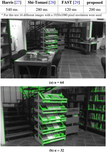
The algorithm was tested with several image sequences and different barrier values. The resulting images are shown in Fig. 6 (detected features are centered in the circles), it demonstrates the flexibility with respect to the corner detection operation. In
Tab. 1 performance comparisons with respect to others feature extraction algorithms commonly used in SLAM formulations are shown. In all cases we program the tested algorithm in a Matlab script. Previous algorithm such as, Harris & Stephens [27] or Shi–Tomasi [28] require exhaustive and complex mathematical operations, then, they require more processing
time that our algorithm. In case of the FAST algorithm [29], its main advantage is low processing time. Although it have lowest processing, the mathematical formulation of our algorithm allows efficient FPGA implementation. Thus, the proposed FPGA accelerator have to manage highest processing time and lowest hardware requirements that any FPGA-based accelerator for the FAST algorithm.
Table 1. General performance for feature extraction algorithms used in SLAM formulations. Harris [27] Shi-Tomasi [28] FAST [29] proposed
540 ms 280 ms 120 ms 200 ms
*For this test 16 different images with a 1920x1080 pixel resolution were used
(a) α = 64
(b) α = 32
Figure 6: Feature extraction algorithm applied over two consecutive frames from a video sequence.
4.2 The feature matching algorithm
In order to present performance comparisons, we implemented several feature matching algorithms suitable for SLAM formulations via Matlab scripts. We matched the features shown in Fig. 6b with the following frame of the video sequence. In
Fig. 7, feature matching performance by applying our algorithm is shown.
Figure 7: Feature-matching algorithm applied over two consecutive frames form a video sequence.
In Tab. 2, we present the mean accuracy for several algorithms previously used in SLAM formulation. In case of the SIFT/ORB algorithms, they allow feature matching along large trajectories in simple form. However, the image degradation between viewpoints introduces data inconsistences that introduce erroneous matches. In order to achieve accuracy required by SLAM applications, statistically robust methods like Random Sample Consensus (RANSAC) have to be implemented to filter erroneous matches. Our algorithm allows high accuracy, superior to SIFT/ORB, suitable for SLAM applications and without any filter or post-processing step. The only limitation compared with SIFT/ORB is that a frame by frame feature matching approach is an exhaustive task. Therefore, the processing time have to be highest than two viewpoint approaches (SIFT/ORB). This can be observed in Tab. 3, were our algorithm and the KLT algorithm, both frame by frame feature-matching algorithms, have highest processing time than SIFT/ORB. Nevertheless, our algorithm has an important advantage because its mathematical formulation allows simple FPGA implementation, suitable for real-time processing. In comparison with previous work we consider that our feature-matching approach can provides a convenient framework for SLAM formulations since it enables high accuracy and allows simple FPGA implementation for real-time processing.
Table 2. General performance for feature matching algorithms used in SLAM formulations (accuracy) KLT [30] ORB [31] SIFT [32] proposed
99% 88% 77% 96%
*For this test 16 different images with a 1920x1080 pixel resolution were used Table 3. General performance for feature matching algorithms used in SLAM formulations (processing speed)
KLT [30] ORB [31] SIFT [32] proposed
2730 ms 417 ms 839 ms 1480 ms
*For this test 16 different images with a 1920x1080 pixel resolution were used
4.3 The smart camera for monocular SLAM
In order to validate the performance, we tested via Matlab several indoor/outdoor video sequences. Although there are several datasets, in most cases several environmental restrictions such as, controlled illumination, uniform camera movements and less image degradation between frames are considered. Environmental restrictions limit the real-world applications performance since these restrictions often not be present. For our experiments we recorded short video sequences from our local library. In Fig. 8, the 3D map and camera pose obtained with our monocular SLAM approach for two viewpoints from a video sequence (Fig. 7) is presented. The location and matching of feature points were carried out with our formulation. An acceptable 3D point location is obtained, qualitatively similar to what can be obtained with previous state of the art monocular-SLAM algorithms. Therefore, the approach is suitable for satisfactory real-world use. In Tab. 4, numerical results for the test shown in Fig. 8 are presented, similar results were obtained for additional indoor/outdoor video sequences.
Table 4. General performance for our SLAM algorithm 3D density Camera pose error Processing time
341 features 0.017% 3716 ms
*For this test, two different viewpoints form a video sequence of 1920x1080 pixel resolution were used. Similar results were obtained for 16 additional sequences.
Figure 7: Results for the proposed SLAM algorithm. Left: front view of the 3D reconstruction and the camera pose for 2 frames. Right: top view of the 3D environment showing the cameras and tracked object.
5. CONCLUSIONS
In this article, we introduced new feature extraction and feature matching algorithms suitable for FPGA implementation, complemented with software processing in the context of an SoC FPGA. The proposed feature extraction and matching algorithms were validated with simulation, and a high level FPGA architecture was introduced. The SLAM implementation delivers satisfactory results similar to previous work, and the hardware-software partition will allow for a compact FPGA smart camera. Since many vision algorithms rely on finding and tracking robust features, we consider the work can be extended to environments with several cameras that can collaborate creating complex 3D maps from the environment. Furthermore, the current hardware/software architecture can serve as a framework for additional vision processing integration that can enrich the monocular SLAM process. As work in progress, the actual FPGA implementation is being explored and a smart camera validation will be presented in a future forum.
6. REFERENCES
[1] OPENCV (Open source Computer Vision): 2015. http://opencv.org/. Accessed: 2016- 15- 05.
[2] Batlle, J., Marti, J., Ridao, P., & Amat, J. 2002. A new FPGA/DSP-based parallel architecture for real-time image processing. Real-Time Imaging, 8(5), 345-356.
[3] Pulli, K., Baksheev, A., Kornyakov, K., & Eruhimov, V. 2012. Real-time computer vision with OpenCV. Communications of the ACM, 55(6), 61-69.
[4] Rud, M. N., & Pantiykchin, A. R. 2014. Development of GPU-accelerated localization system for autonomous mobile robot. In Mechanical Engineering, Automation and Control Systems (MEACS), 2014 International Conference on (pp. 1-4). IEEE.
[5] Vega, A., Lin, C. C., Swaminathan, K., Buyuktosunoglu, A., Pankanti, S., & Bose, P. 2015. Resilient, UAV-embedded real-time computing. In Computer Design (ICCD), 2015 33rd IEEE International Conference on (pp. 736-739). IEEE.
[6] Sérot, J., Berry, F., & Ahmed, S. 2013. Caph: A language for implementing stream-processing applications on
FPGAs. In Embedded Systems Design with FPGAs (pp. 201-224). Springer New York.
[7] GPStudio: 2015. http://gpstudio.univ-bpclermont.fr/. Accessed: 2016- 15- 05.
[8] OpenCL (Open Computing Language): 2015. https://www.altera.com/products/design-software/embedded-software-developers/opencl/ overview.html/. Accessed: 2016- 15- 05.
[9] OpenVX: 2015. https://www.khronos.org/openvx/. Accessed: 2016- 15- 05.
[10] Fuentes-Pacheco, J., Ruiz-Ascencio, J., & Rendón-Mancha, J. M. 2015. Visual simultaneous localization and mapping: a survey. Artificial Intelligence Review, 43(1), 55-81. [11] Kong, W., Zhou, D., Zhang, D., & Zhang, J. 2014.
Vision-based autonomous landing system for unmanned aerial vehicle: A survey. In Multisensor Fusion and Information Integration for Intelligent Systems (MFI), 2014
International Conference on (pp. 1-8). IEEE.
[12] Lee, C. S., Nagappa, S., Palomeras, N., Clark, D. E., & Salvi, J. (2014). Slam with sc-phd filters: An underwater vehicle application. Robotics & Automation Magazine, IEEE, 21(2), 38-45.
[13] Bourrasset, C., Maggianiy, L., Sérot, J., Berry, F., & Pagano, P. 2013. Distributed FPGA-based smart camera architecture for computer vision applications. In Distributed Smart Cameras (ICDSC), 2013 Seventh International Conference on (pp. 1-2). IEEE.
[14] Birem, M., & Berry, F. (2014). Dreamcam: A modular fpga-based smart camera architecture. Journal of Systems Architecture, 60(6), 519-527.
[15] Engel, J., Schöps, T., & Cremers, D. 2014. LSD-SLAM: Large-scale direct monocular SLAM. In Computer Vision– ECCV 2014 (pp. 834-849). Springer International Publishing.
[16] Mur-Artal, R., Montiel, J. M. M., & Tardos, J. D. 2015. ORB-SLAM: a versatile and accurate monocular SLAM system. Robotics, IEEE Transactions on, 31(5), 1147-1163.Birem, M., & Berry, F. (2014). Dreamcam: A
modular fpga-based smart camera architecture. Journal of Systems Architecture, 60(6), 519-527.
[17] Herrera, C., Kim, K., Kannala, J., Pulli, K., & Heikkila, J. 2014. DT-SLAM: Deferred Triangulation for Robust SLAM. In 3D Vision (3DV), 2014 2nd International Conference on (Vol. 1, pp. 609-616). IEEE.
[18] Spampinato, G., Lidholm, J., Ahlberg, C., Ekstrand, F., Ekstrom, M., & Asplund, L. 2013. An embedded stereo vision module for industrial vehicles automation. In Industrial Technology (ICIT), 2013 IEEE International Conference on (pp. 52-57). IEEE.
[19] Nikolic, J., Rehder, J., Burri, M., Gohl, P., Leutenegger, S., Furgale, P. T., & Siegwart, R. 2014. A synchronized visual-inertial sensor system with FPGA pre-processing for accurate real-time SLAM. In Robotics and Automation (ICRA), 2014 IEEE International Conference on (pp. 431-437). IEEE.
[20] Mattoccia, S., & Macri, P. 2014. A Real Time 3D Sensor for Smart Cameras. In Proceedings of the International Conference on Distributed Smart Cameras (p. 29). ACM. [21] Bonato, V., Fernandes, M. M., & Marques, E. 2006. A
smart camera with gesture recognition and SLAM capabilities for mobile robots. International journal of electronics, 93(6), 385-401.
[22] Aguilar-González, A., Arias-Estrada, M., Pérez-Patricio, M., & Camas-Anzueto, J. L. 2015. An FPGA 2D-convolution unit based on the CAPH language. Journal of Real-Time Image Processing, 1-15.
[23] Bobda, C., & Velipasalar, S. 2014. Distributed Embedded Smart Cameras. Springer.
[24] Hartley, R., & Zisserman, A. 2003. Multiple view geometry in computer vision. Cambridge university press.
[25] Pérez-Patricio, M., & Aguilar-González, A. 2015. FPGA implementation of an efficient similarity-based adaptive window algorithm for real-time stereo matching. Journal of Real-Time Image Processing, 1-17.
[26] Di Stefano, L., Marchionni, M., & Mattoccia, S. 2004. A fast area-based stereo matching algorithm. Image and vision computing, 22(12), 983-1005.
[27] Harris, C., & Stephens, M. 1988. A combined corner and edge detector. In Alvey vision conference (Vol. 15, p. 50). [28] Tommasini, T., Fusiello, A., Trucco, E., & Roberto, V.
1998, June. Making good features track better. In Computer Vision and Pattern Recognition, 1998. Proceedings. 1998 IEEE Computer Society Conference on (pp. 178-183). IEEE.
[29] Rosten, E., & Drummond, T. 2005. Fusing points and lines for high performance tracking. In Computer Vision, 2005. ICCV 2005. Tenth IEEE International Conference on (Vol. 2, pp. 1508-1515). IEEE.
[30] Lucas, B. D., & Kanade, T. (1981, August). An iterative image registration technique with an application to stereo vision. In IJCAI (Vol. 81, pp. 674-679).
[31] Rublee, E., Rabaud, V., Konolige, K., & Bradski, G. 2011. ORB: an efficient alternative to SIFT or SURF. In Computer Vision (ICCV), 2011 IEEE International Conference on (pp. 2564-2571). IEEE.
[32] Lowe, D. G. 1999. Object recognition from local scale-invariant features. In Computer vision, 1999. The proceedings of the seventh IEEE international conference on (Vol. 2, pp. 1150-1157). Ieee.
[33] CadenceGroup: 2016. http://ip.cadence.com. Accessed: 2016- 15- 05.