HAL Id: tel-01867292
https://tel.archives-ouvertes.fr/tel-01867292
Submitted on 4 Sep 2018HAL is a multi-disciplinary open access archive for the deposit and dissemination of sci-entific research documents, whether they are pub-lished or not. The documents may come from teaching and research institutions in France or abroad, or from public or private research centers.
L’archive ouverte pluridisciplinaire HAL, est destinée au dépôt et à la diffusion de documents scientifiques de niveau recherche, publiés ou non, émanant des établissements d’enseignement et de recherche français ou étrangers, des laboratoires publics ou privés.
Study of chemical reactivity of MAX phase single
crystals
Shiqi Zhang
To cite this version:
Shiqi Zhang. Study of chemical reactivity of MAX phase single crystals. Organic chemistry. Université Grenoble Alpes, 2018. English. �NNT : 2018GREAI042�. �tel-01867292�
THÈSE
Pour obtenir le grade de
DOCTEUR DE LA COMMUNAUTE UNIVERSITE
GRENOBLE ALPES
Spécialité : Matériaux, Mécanique, Génie civil, Electrochimie
Arrêté ministériel : 25 mai 2016
Présentée par
Shiqi ZHANG
Thèse dirigée par Thierry OUISSE et codirigée par Olivier DEZELLUS
préparée au sein du Laboratoire des Matériaux et du Génie Physique dans l`IMEP-2
Etude de la réactivité chimique des
monocristaux de phase MAX
Thèse soutenue publiquement le 26 février 2018 devant le jury composé de :
Dr. Gilles Hug
Directeur de recherche, ONERA, Président
Dr. Thierry Cabioch
Professeur, Université de Poitiers, rapporteur
Dr. Catherine Journet
Professeur, UCBL Lyon, rapporteur
Dr. Olivier Dezellus
Maitre de conférences, UCBL Lyon, co-directeur de thèse
Dr. Thierry, Ouisse
2
General information
The current thesis was elaborated in Laboratoire des Matériaux et du Génie Physique (LMGP) of Grenoble INP and it was financially supported by the Agence Nationale de la Recherche on MAX phase single crystal “MAXICRYST” (March 2014 - 42 months). The core of scientific objective of the MAXICRYST program is aimed to overcome the technological barrier limiting the improvement of large MAX phases single crystals and to get forward in the physical, chemical and mechanical properties.
The work of the current thesis undertakes one part of the project and mainly deals with the chemical reactivity of MAX phase single crystal. Collaborations were mainly achieved with 4 partners involving three laboratories in France and one in the USA. The first part of the thesis of one year and three months took place in the Le Laboratoire des Multimatériaux et Interfaces of university Claude Benard Lyon 1. Synthesis of MXene from MAX phase single crystal is performed there (the results are presented in Chapter 2). A following cooperation of several months is achieved in “Laboratoire de Science et Ingénierie des Matériaux et Procédés” of Grenoble INP in France. Conversion of MAX phase single crystals into highly porous carbides by high-temperature chlorination is elaborated by a CVD reactor (the results are given in Chapter 3) and a journal article was published including an oral presentation in European Ceramic Society Conference. Crystalline orientation dependent electrochemical behaviors of single crystal Cr2AlC in 1M H2SO4 was investigated in “Electrochimie et physicochimie des
matériaux et des interfaces” of Grenoble INP in France. A correspondent journal article is being produced now. Results are presented in Chapter 4. At last, a close collaboration took place with Prof. Michel Barsoum of Department of Materials Science and Engineering at Drexel University in the USA. Crucial indirect evidence of ripplocation in polished and electrochemically etched Cr2AlC single crystals, based on the samples prepared in LEPMI, was
discovered, for a better understanding of the ripplocation in layered solids.
This thesis will bring some original viewpoints into the field of chemical reactivity of MAX phase single crystals. The topics that were investigated are 1) Synthesis of MXene from MAX phase single crystal based on the anisotropic chemical reactivity. The aim is to acquire large-scale MXene taking advantage of large size single crystal. This requires a thorough study of etching agent selection and mechanism 2) Chemical reactivity in chlorination: the initial purpose is to obtain MXene as an intermediate product in chlorination. However, we present another attractive derivative of MAX, porous chromium carbides that exhibit several interesting
3
properties. 3) Anisotropic electrochemical resistance. Large size single crystals are the first time used as electrode for the electrochemical tests. Significant anisotropy is shown by electrochemical polarization and EIS. 4) Ripplocation in MAX phase. A recently discovered new dislocation type, ripplocation is indirectly demonstrated in mechanically polished MAX phase single crystal through polarization.
According to the investigated topics, the structure of the current thesis is as below. The first chapter starts with an introduction to MAX phase involving research history, structure, physical and chemical property and applications. The most attractive derivative product MXene is emphatically introduced. Then, all the growth techniques of MAX phase are introduced including the method for large single crystals used in the current thesis. At the end, the main contribution of the present thesis to MAX phase world is mentioned.
In the second chapter, we present details of the synthesis of MXene from MAX phase single crystals. Chemical and electrochemical methods are attempted to extract MXene from the MAX phases. Furthermore, based on the results, chemical reactivity is presented in different etching environments.
In the third chapter, we investigate the conversion of MAX phase single crystals into highly porous carbides by high-temperature chlorination. The morphology and structure are characterized by SEM and XRD. The effect of the various crucible parameters such as temperature and time are presented by Raman spectroscopy. We also demonstrate the magnetoresistance of porous Cr-C for the first time and the result shows that it is in the same magnitude with dense bulk one. The reaction mechanism is also investigated by XRD and Raman spectroscopy so as to understand the chemical anisotropic reactivity based on Al.
The fourth chapter is dedicated to exploring the anisotropic behavior of MAX phase single crystals in electrochemical environment. The evidence is given through a combined investigation of experimentally obtained polarization results and EIS analysis coupled with simulated equivalent circuits. Therein, possible mechanisms are discussed concerning the anisotropic reactivity. Furthermore, we show that the shape and morphology of defects created by mechanically polishing large Cr2AlC single crystals are consistent with the nucleation of
recently discovered new dislocation, bulk ripplocations.
At the end, general conclusions and prospective for future research close the presentation of current thesis.
4
Summary of the thesis
MAX phases are a family of layered ternary carbides and nitrides with chemical formula Mn+1AXn, where M is an early transition element, A is an element of groups 13 to16 and X is
either C, N or both. These phases combine the merits of ceramics and metals, such as chemical stability, machinability, shock resistance, good electrical and thermal conductivity, etc. However, the investigation of their intrinsic properties and anisotropies has heretofore been limited by a lack of availability of single crystals. This thesis mainly deals with the chemical reactivity of MAX phase single crystals. Owing to the large size single crystals grown at LMGP, it was possible to directly assess the anisotropy of the chemical reactivity and to obtain original data. We showed that the prominent role played by the A element for initiating chemical transformations could lead to the synthesis of original materials, and we focused on four different aspects. First, we tried to synthesize MXenes from MAX phase single crystals: The purpose was to obtain large-scale MXenes by taking advantage of the large size of the single crystals. Effort was put on describing the chemical reactivity of MAX phases dipped in different etchants, focusing on HF. Secondly, we studied the MAX phase reactivity with chlorination: the initial purpose was to obtain MXenes, but we finally developed a method for synthesizing porous chromium carbides which exhibit several interesting properties. Thirdly, we used large size single crystals in order to assess the anisotropy of the electrochemical properties. A significant anisotropy was found, either by measuring the current during electrochemical polarization or by frequency-dependent impedance measurements. Several mechanisms were proposed in order to explain this anisotropy of the corrosion properties. Eventually, we showed that the electrochemical results could be used to indirectly evidence the presence of structural defects recently identified in the literature. Such defects, called ripplocations, are specific to nano-lamellar materials.
5
Résumé de thèse
Les phases MAX forment une famille de carbures et de nitrures nano-lamellaires de formule chimique Mn+1AXn, où M est un métal de transition des premières colonnes, A
appartient aux colonnes 13-16 et X est soit C, soit N, ou une combinaison des deux éléments. Ces phases combinent les mérites des céramiques et des métaux, comme une bonne stabilité chimique, l’usinabilité, la résistance aux chocs mécaniques, de bonnes conductivités thermique et électrique, etc. Malgré tout, l’étude de leurs propriétés intrinsèques et de leurs anisotropies a été jusqu’à présent limitée par l’indisponibilité de monocristaux. Cette thèse traite de la réactivité de tels monocristaux de phases MAX. Grâce à la large taille des cristaux produits au LMGP, il a été possible d’évaluer directement l’anisotropie de la réactivité chimique et d’obtenir des données originales. Nous avons montré le rôle prépondérant joué par l’élément A pour initier des transformations chimiques menant parfois à la synthèse de matériaux originaux, et nous nous sommes concentrés sur quatre aspects différents : Tout d’abord, nous avons tenté de synthétiser des MXènes de grande taille, en profitant de la grande taille des cristaux disponibles. Un effort particulier a été porté sur la description de la réactivité chimique de phases MAX plongées dans diverses solutions d’attaque, avec un accent particulier mis sur l’utilisation de HF. En second lieu, nous avons étudié la chloruration de phases MAX : l’objectif initial était de former des MXènes, mais nous avons finalement développé une méthode pour synthétiser des carbures de chrome poreux avec des propriétés intéressantes. Troisièmement, nous avons utilisé des cristaux de grande taille pour évaluer l’anisotropie des propriétés électrochimiques. Une anisotropie significative a été trouvée, soit en mesurant le courant durant la polarisation électrochimique, soit par mesure de spectroscopie d’impédance. Divers mécanismes ont été proposés afin d’expliquer cette anisotropie des propriétés de corrosion. Enfin, nous avons montré que les résultats électrochimiques pouvaient être utilisés pour révéler indirectement la présence de défauts structurels récemment identifiés dans la littérature. De tels défauts, appelés « ripplocations », sont spécifiques aux matériaux nano-lamellaires.
6
Acknowledgement
First of all, I would like to express my heartfelt gratitude to my supervisor Dr. Thierry Ouisse for his help, strong support, sincere encouragement, and enthusiasm related to my thesis, great tutoring, significant advice and his confidence in me. Hence, all can be concluded in one sentence: THANK YOU!
From the beginning of 2016, I started to work with Thierry at LMGP. He taught me everything in detail, from the preparation of scientific figures to science writing, from theoretical knowledge to experimental operation. Each time I made the unprofessional results, he was always patient and gave me significant advice, which help me to make large progress. Every comment, advice, and discussion could be the precious gift for my future career. I would like to appreciate all the patients and support from him to help me to finish my thesis and grow up in science life.
I would like also to give great appreciation to my co-supervisor, Dr. Olivier Dezellus, for the first-year teaching. With Olivier, I started to learn how to deal with the Ph.D. work and feel enjoyable for the research life.
I think myself very lucky and honored for collaborating with a number of wonderful persons during my Ph.D. in France.
Great appreciation should be given to all the members at LMI in Lyon, Jérôme Andrieux, Bruno Gardiola, Erwann Jeanneau and Nassim Samer for the help and advice in and out of Lab for their friendship.
I would like also to thank the permanents at LMGP, Odette Chaix, Isabelle Gélard, Laetitia Rapenne-Homand, Eirini Sarigiannidou, Herve Roussel for giving me the patient technique training and helping me much for the sample characterizations.
Fortunately, I had the precious opportunity to work with the members of TOP at Lab SIMAP, Fréderic Mercier, Roman Reboud, Raphael Boichot, and Maeva Chen. I should give large appreciation to them for the CVD reactor training and kindly settle with the tense apparatus arrangement schedule.
As well, I should thank another cooperation partners at LEPMI whose support me all the electrochemical devices to extend our study on MAX phase. Dr. Virginie Roche and Dr. Fanny Hilario gave me a systemical training for the electrochemistry and worked a lot for helping me to interpret experimental results, inspiriting discussions, great suggestions. Mr.
7
Vincent Martin helped to measure the porosity of chromium carbides which provides me important information about our products.
I should also give great appreciation to the research leaders Dr. Didier Chaussende and Dr. Michael Barsoum. The former accompanied me at the beginning of the project and gave me a lot of suggestions. The latter spend time with me for the significant discussion for our work, not only in the investigation of mechanical dislocation of MAX phase but also in all other studies in terms of MAX phases.
I would like also to thank Dr. Franz Bruckert and Dr. Maria Carmen Jimenez Arevalo for giving me very kind encouragement and advice in my thesis and science career. As well, Michèle San Martin and Virginie Charriere help me in solving administrative problems, friendly advice, and support.
Fortunately, I could invite Dr. Catherine Journet-Gauthier and Dr. Thierry Cabioch to review my thesis and to be rapporteurs and juries in my defense committee. The same appreciation is also given to Dr. Gilles Hug as the jury in my defense committee.
I would like also to thank my colleagues Dr. Lu Shi and Dr. Hongjun Liu who helped me a lot to be familiar with the laboratory in the beginning and helped me in and out of Lab. As well, I should appreciate all other Ph.D. student colleagues in group Christallogenese at LMGP, Yun Ji Shin Hoang-Long Le-Tran, Damir Pinek for making my thesis an enjoyable and unforgettable experience.
Finally, I would like to thank my parents and girlfriend, for their comprehension, care and support without reservation. Without their accompanying and care, the thesis would not have been possibly completed. My parents teach me all the life knowledge and bring me up for life. I owe everything to them.
8
Contents
General information ... 2
Summary of the thesis ... 4
Résumé de thèse ... 5
Acknowledgement ... 6
Chapter 1 Introduction: MAX phase history, background, growth methods and applications ... 11
1.1 History ... 12
1.2 Structure and defects... 13
1.2.1 Atom position and stacking sequences ... 14
1.2.2 Lattice parameters, bond length and interlayer thickness ... 17
1.2.3 Defects ... 19
1.3 Characteristics ... 21
1.3.1 Surface morphology ... 22
1.3.2 Vibration modes detected by Raman spectroscopy ... 23
1.4 Physical properties ... 25 1.4.1 Hardness ... 25 1.4.2 Fatigue resistance... 25 1.4.3 Damage tolerance ... 26 1.4.4 Machinability ... 27 1.5 Chemical properties ... 27 1.6 Mxenes ... 29 1.6.1 Synthesis ... 29 1.6.2 Structure ... 33 1.6.3 Properties ... 35
1.7 Applications of MAX phases ... 39
1.7.1 Replacement of Graphite in high Temperature applications ... 39
1.7.2 Heating Elements ... 40
1.7.3 High-Temperature Foil Bearings and Other Tribological Applications ... 41
1.7.4 Gas Burner Nozzles ... 41
1.7.5 Tooling for Dry Drilling of Concrete ... 42
1.7.6 Glove and Condom Formers and Nonstick Cookware ... 43
1.7.7 Applications in the Nuclear Industry ... 43
9
1.7.9 Electrical Contact for SiC-based Devices ... 44
1.7.10 Forming Processes and Sintering... 45
1.8 synthesis ... 46
1.8.1 Polycrystalline materials ... 46
1.8.2 Single crystalline materials ... 48
1.9 Objectives of this work ... 52
References ... 55
Chapter 2 exfoliation of MAX phase to Mxene ... 66
2.1 Introduction ... 67
2.2. Experiments and results ... 67
2.2.1 Chemical method ... 68
2.2.1.1 HF solution and HF based solution………...72
2.2.1.2 Exfoliation in EDTA……….85
2.2.1.3 Electrochemical etching………...….89
2.3 Conclusion ... 97
Annex Calculation of pH and pF ... 103
Chapter 3 High temperature chlorination ... 106
3.1 High Temperature Chlorination ... 107
3.2 Previous work and purpose of our own study ... 107
3.3 Chromium carbide ... 108
3.3.1 Introduction ... 108
3.3.2 Industry fabrication method ... 109
3.3.3 Application ... 110
3.3.4 Fabrication of Chromium carbide reference sample... 111
3.3.5 Porous Cr3C2... 112
3.4 MAX phase high temperature chlorination ... 112
3.4.1 Experimental set-up ... 112
3.4.2 Chlorination process ... 114
3.4.3 Products ... 115
3.5 Conclusion ... 136
Reference ... 138
Chapter 4 Electrochemical anisotropy of MAX phase Cr2AlC ... 143
4.1 Introduction ... 144
4.1.1 Electrochemical method ... 144
10
4.1.3 Anisotropic properties and resistance to corrosion ... 146
4.1.4 Evidence of ripplocations by electrochemical etching ... 148
4.1.5 Objectives and content of this chapter ... 151
4.2 Methodology ... 151
4.2.1 Raw material:... 151
4.2.2 Electrode sample preparation ... 152
4.2.3 Electrochemical tests ... 152
4.2.4 Characterization technics ... 154
4.3 Results and discussion ... 154
4.3.1 Indirect evidence for ripplocations ... 154
4.3.2 Electrochemical measurements ... 163
4.4 Corrosion mechanism analysis ... 171
4.5 Conclusion ... 174
Reference ... 175
11
Chapter 1 Introduction
MAX phase history, background, growth methods
and applications
This chapter gives some background information about MAX phases, MAX phase single crystals and growth techniques. First, an overall introduction to the MAX phase development history will be given from the 1960s until now. Then we focus on some important MAX phase properties, and summarize the existing and potential applications proposed by some companies and laboratories. Finally, we describe the techniques of synthesis of MAX phases, and we close this chapter by listing the contributions of this work to the field of MAX phase single crystals.
12
1.1 History
MAX phase is a family of lamellar, hexagonal carbides and nitrides with the chemical formula Mn+1AXn (n=1, 2 or 3), where M is an early transition metal, A is an element from
groups 13 to 16, and X is carbon, nitrogen or both.
MAX phases were discovered in the sixties, but one had to wait until 1996 for the beginning of a systematic and intense research activity. In the 1960s, H. Nowotny and co-workers discovered a large family of ternary lamellar carbides and nitrides, which they called the 'H' phases [1-4] with formula T2MC, now identified as the M2AX phases (i.e. n = 2), and
several M3AX2 phases such as Ti3SiC2 and Ti3GeC2 [5-7]. From then on, it opened the doors
of MAX phase investigation. In their studies, the crystalline structures were adequately studied by X-ray diffraction. The crystal structures, with hexagonal atomic arrangement, are given in figure 1.1. M3X2 layers are separated by A layers [1]. Then Nickl et al. [8] and Japanese
scientists T. Goto et al. [9] tried to synthesize polycrystals of Ti3SiC2 by chemical vapor
deposition from chloride sources. Unlike other transition metal-carbides, Ti3SiC2 showed an
unusual anisotropic hardness, for the hardness perpendicular to the basal plane is roughly three times larger than that parallel to the basal plane. Other unusual properties were also evidenced, such as high-temperature resistance and stiffness.
However, obtained crystals were always mingled with impurities at an early stage. For example, sintering in system Cr-Al-C does not only produce Cr2AlC but also contains Cr7C3
and Cr3C2 [3]. The purity of the best result was limited to 80-90% [10], which influenced the
characterization and stability of these novel materials, and prevented their use on potential applications. As a consequence, the discovery of those new lamellar compounds did not attract so much interest. The research was all but active, until it went to a turning point in 1996. Fully dense and pure Ti3SiC2 phase was successfully synthesized in the research group of M.
Barsoum in Drexel, through the hot-pressing method, and fully characterized for the first time. Analysis revealed this phase to possess a distinct combination of some of the best properties of metals and engineering ceramics [11]. Since 1996, when the seminal paper was published, a significant amount of MAX phases has now revealed to exhibit quite similar attractive properties. Since then, the method of hot pressed sintering has been extensively used for synthesizing MAX phases with different seal crucibles, depending on the A element [1-7].
13
Moreover, tremendous progress has been made for understanding the properties of these phases. The investigation of oxidation resistance was performed on Ti3SiC2 [12] and showed
that the oxidation kinetics was importantly influenced by oxygen diffusion and Ti. Then, in 1999, Barsoum’s group paid much attention to the Ti-Al-N system [13]. They synthesized Ti4AlN3 (413 MAX phase) and realized that they were able to deal with a much larger family
of solids that thought initially, which all behaved similarly. During the last 15 years, the researchers recognized that these phases represent a new class of thermodynamically stable Nano-laminated solids. At an early stage, the 211 phases were named M2BX or H phases. In
the 1980s, as the international union of pure and applied chemistry has published a new modified periodic table, accordingly, aluminum and silicon are defined in the A group. So Barsoum et al. re-named the H-phases and their counterparts with n>2 as Mn+1AXn, or as “MAX”
phases. Since 2006 researchers have preferentially focused on the solution of two fundamental problems: manufacturing cost and sample size. Making large parts is still not commercially viable. In 2013, T.Ouisse et al. [14] succeeded to grow MAX phase single crystal Cr2AlC by
the high-temperature solution growth method. After some effort, the size of Cr2AlC crystals has
increased from hundreds of square microns to several square centimeters. Then this technique has been extended to the synthesis of other phases. Many phases can now be obtained in single crystal form, such as V2AlC and Ti3SiC2. The availability of single crystals made possible a
detailed investigation of the anisotropic physical properties. Furthermore, new fabrication methods, extensive characterization of all kinds and composites implementation of MAX phase materials have been explored. Doped phases, like aluminum-MAX phase composites, have largely improved mechanical properties like ductility and toughness over pure MAX phase material [15]. More complex multi-M/A phases such as Ti3(Si0.43Ge0.57)C2[16] have been
discovered, sometimes possessing additional attractive properties as compared to the simple MAX phases. Research on MAX phases is now a very active field, and more than 100 phases have been discovered.
14
In this section, we summarize some published research results on the crystal structure and related issues, in order to provide the information necessary to understand the reason why and how are established the physical properties.
1.2.1 Atom position and stacking sequences
The usual Mn+1AXn phase compounds have a structure with hexagonal symmetry, which
belongs to the space groupD4
6h (P63/mmc), with the repetition of two formula units per unit cell.
In each case, adjacent closed packed Mn+1Xn layers are separated by a pure A group layer, and
X atoms occupy octahedral sites between the M layers [17]. The layered nature of these compounds is visible in Fig.1.1 and 1.2. The M6X units share their edges and are the same as
those observed in the rock salt structure. The A-group atoms are situated at the center of trigonal prisms that are larger than the octahedral sites and thus enable to accommodate big A atoms. The differences between the structures with various n values is illustrated in Figure1.1a-c. The majority of existing compounds belong to the 211 phases and the most usual A element is aluminum, with around 13 compounds including carbides and nitrides.
Figure 1.1. Unit cells of (a) 211 (b) 312 and (c) 413 phases. The c lattice parameters are shown by vertical dashed lines. dx represents the distance from the nearest hcp planes containing the transition
metal atoms; dα is the same parameter but for the A layers. Those distances are connected together by
15
Figure 1.2. Schematics of the (11-20) zone axis for the phases (a) M2AX, (b) α-M3AX2, (c) β-M3AX2,
(d) α-M4AX3, (e) β-M4AX3 and (f) γ- M4AX3. Note that only in the α-M3AX2 structure the A atoms lie
on top of each other [17].
The density (D) and lattice parameters (a, c) of MAX phase compounds are listed in Table 1.1 [18-31]. As to the 211 phases, there is just one polymorph (Figure 1.2a). In the 312 phases, there are two polymorphs, α and β, shown in Figures 1.2b and c, respectively. For the 413 cases, there are three polymorphs: α, β, and γ, shown in Figures 1.2d, e and f, respectively. In these arrangements, the capital and lower-case letters depict the M and A layers. The Greek letters represent the X positions corresponding to roman letter counterpart. α is an A site, β is a B site, and so on. These sequences are best appreciated when the (11-20) planes are sketched, respectively (Fig1.2a,b,d). The A element planes are mirror planes, and the MX blocks are zig-zagged, in agreement with the TEM analysis [32].
The stacking sequences for the corresponding α phase are
BγAbAγBaBγAbAγB……M2AX
AγBaBγAβCaCβAγBaBγA…… α-M3AX2
α BcBαCβAγBaBγAβCαBcB.αC….. α-M4AX3
The stacking sequences for the corresponding β phase are
AγBcBγAβCbCβAγBcBγA…… β -M3AX2
16 Lastly, the sequence for the γ- M4AX3 structure is
αBaBαCβAγBcBγAβCαBaBαC…. γ- M4AX3
There have been recent discoveries of MAX phases with n=4 and 5. However, what is currently unclear is whether these compositions can be synthesized as a single phase in mass or whether they are only small regions with high densities of stacking faults. Hybrid structures also exists as well. The earliest ones were reported in the Ti-Si-C system [32].
Table 1.1. Density and lattice parameters of 77 Max phase compounds. [18-31,33] Table 2.1. Density and lattice parameters of 77 Max phase compounds[17].
No. Compounds Density D, ( Mgm-3) Lattice parameters a, c(Å)
211 Phases 1 Sc2AlC 2.99 3.280, 15.373 2 Sc2GaC 3.93 3.253, 15.813 3 Sc2InC 4.72 3.272, 16.452 4 Sc2TlC 6.60 3.281, 16.530 5 Ti2AlC 4.11 3.051, 13.637 6 Ti2AlN 4.31 2.989, 13.614 7 Ti2SiC 4.35 3.052, 12.873 8 Ti2PC 4.56 3.191, 11.457 9 Ti2SC 4.62 3.216, 11.22 10 Ti2GaC 5.53 3.07, 13.52 11 Ti2GaN 5.75 3.00, 13.3 12 Ti2GeC 5.30 3.07, 12.93 13 Ti2AsC 5.71 3.209, 11.925 14 Ti2CdC 9.71 3.1, 14.41 15 Ti2InC 6.30 3.134, 14.077 16 Ti2InN 6.54 3.07, 13.97 17 Ti2SnC 6.10 3.163, 13.679 18 Ti2TlC 8.63 3.15, 13.98 19 Ti2PbC 8.55 3.20, 13.81 20 V2AlC 4.07 3.1, 13.83 21 V2SiC 5.20 2.955, 11.983 22 V2PC 5.38 3.077, 10.91 23 V2GaC 6.39 2.93, 12.84 24 V2GaN 5.94 3.00, 13.3 25 V2GeC 6.49 3.00, 12.25 26 V2AsC 6.63 3.11, 11.3 27 Cr2AlC 5.21 2.863, 12.814 28 Cr2GaC 6.81 2.88, 12.61 29 Cr2GaN 6.82 2.875, 12.77 30 Cr2GeC 6.88 2.95, 12.08 31 Zr2AlC 5.78 3.2104, 14.2460 32 Zr2AlN 5.83 3.2155, 14.2134 33 Zr2SC 6.20 3.40, 12.13 34 Zr2InC 7.1 3.34, 14.91 35 Zr2InN 7.53 3.27, 14.83 36 Zr2SnC 6.9 3.3576, 14.57 37 Zr2TlC 9.17 3.36, 14.78 38 Zr2TlN 9.60 3.3, 14.71 39 Zr2PbC 8.2 3.38, 14.66 40 Nb2AlC 6.50 3.10, 13.8 41 Nb2PC 7.09 3.28, 11.5 42 Nb2SC0.4 7.01 3.27, 11.4 43 Nb2SCx - -
17
1.2.2 Lattice parameters, bond length and interlayer thickness
1.2.2.1 Lattice parameters
Fig.1.1 shows the fundamental stacking building blocks of MAX phases with the edge-sharing MX6 octahedra. A good correlation exists between the a lattice parameters and two
adjacent M-M atoms interval distance dM-M in the MX binaries [17]. For other MAX phases,
the exception is the Cr-C system because Cr-C compounds do not crystallize in the rock salt structure. The two adjacent M atoms distance dM-M is usually investigated in C-N system that
does exist in the rock salt structure. The c lattice dependencies on M atoms interval distance and a element diameter dA can be summarized as follows: Firstly, for phases with the same A
element, the c parameter increases linearly as a function of dM-M. M3AlX2 phases follow the
same rule [34]. Secondly, the relationship between the c parameter and A atom diameter dA is
complex. A non-linear dependence can be separated into three regimes. For dA<2.5Å, the c
lattice parameter has small values and increases slightly with increasing dA. Around 2.5 Å, the
c lattice exhibits an almost step like dependence on dA. For dA >2.6Å, the c parameter is
relatively independent on dA.
The ratio between c/a for the 211 phases ranges from 3.5 to 4.6, where the P-, S-, and As containing ternaries have the lowest values [17]. Accordingly, we can assume that the ternary phases are filled with A and X atoms in interstitial sites between M atoms. In this case, the c parameter, including four M layers per unit cell, could reasonably be around four times the a parameter, which is equal to dM-M. By such analogy, the 312 and 413 phases are predicted
to exhibit a ratio around 6 and 8 respectively [17].
1.2.2.2 Bond length
Once the canonical position zi values and lattice parameters are known, all the bond
lengths and bond angles in the structures can be calculated. For example, for the 211 phases, the following applies [35]:
𝑅"#$ = &𝑎( 3 + 𝑧"(𝑐( 𝑹𝑴#𝑨 = & 𝒂𝟐 𝟑 + ( 𝟏 𝟒− 𝒛𝑴)𝟐𝒄𝟐
18
𝑹𝑴𝟏#𝑴𝟐 = 𝒂 (In plane M atoms)
For the out-of-plane atoms:
𝑅"#$ = &𝑎(
3 + 4𝑧"(𝑐(
Table 1.2. Summary of experimental bond distance (Å), deduced from the lattice parameters and the zi
parameters for select Ti-containing MAX and MX phases. [42]
MAX M1-A M1-X1 M1-M2 M1-M1 M2-M1 M2-X2 Reference Ti2AlC 2.846 2.116 2.905 3.064 - - [35] at 10K 2.855 2.119 2.942 3.058 - - [41] at 400K Ti2AlN 2.823 2.087 2.910 2.994 - - [3] 2.837 2.086 2.0905 2.995 - - [35] at 10K Ti3SiC2 2.696 2.135 2.971 3.068 2.135 - [36] 2.693 2.085 2.963 3.066 2.181 - [37] 2.681 2.088 2.963 3.058 2.176 - [38] Ti4AlC2.9 2.818 2.087 2.913 2.988 2.093 2.141 [39] TiC - 2.165 - 3.062 - - [40] TiN - 2.120 - 2.997 - - -
Table 1.2 compares the various bond lengths of selected Ti-containing MAX phases with those in MX binaries TiC and TiN. In general, the bond length in the MX compound is relatively similar to those in the MAX phase. However, there are still some significant differences and trends. Based on table 1.2, the M1-X bonds in 211 and 312 phases are all shorter
than those in MX binaries.
The rule for 413 phases becomes slightly different in comparison with the 211 and 312 phases, because two M layers are solely bonded to X atoms. For example, the Ti1-N1 bondings
in the octahedral nearest the A layer, are significantly shorter that those Ti2-N2 in the center of
19
1.2.2.3 Interlayer thickness
Based on the results in the literatures [23,42], the compression of the layer along [0001] orientation of the octahedra increases as the latter are closer to an A layer. This is proved by the fact that in all cases, the interlayer distance follows the trend: Ti1-C1(d1)<Ti2-C2(d2)<Ti3-C3(d3).
Furthermore, the M-A interlayer distance-D is a relatively independent of the number n. Besides, the M1-X1 interlayer distance-D1 is less than the corresponding distance in the binary.
An opposite trend applies to D2. The Ta-C distance in the binary is roughly the average of the
Ta-C distances in the ternaries. This is only valid in both Ti-Al-C and Ta-C systems. [23].
1.2.3 Defects
1.2.3.1 Vacancies
The vacancies exist in all solid materials, both for thermodynamic and process reasons. In some cases, their role is extremely important. However, it is really difficult to determine the chemical stoichiometry by wavelength dispersive spectroscopy (WDS) or energy dispersive x ray spectrometry (EDS). By EDS, the carbon quantity is difficult to assess, due to the light atomic mass. WDS often gives unclear results. Some assumptions bring up that the clear XRD diffractograms can confirm the formal ratio of the elements of the MAX phases [43,44]. However, this is not always true. For example, the actual stoichiometric chemistry of Ti4AlN3
is Ti4AlN2.9 with a N sub-stoichiometry verified by clear WDS measurements [45].
Therefore, we have to admit our poor knowledge about vacancies in MAX phase materials, especially the defect energy and occurring positions. Until now, Ti3SiC2 is one of the
most stoichiometric phases, and appears to be significantly stable.
As mentioned above, the actual chemistry of Ti4AlN3 is Ti4AlN2.9. This investigation
prompted further investigations which simulated the vacancies in Ti4AlN3 through ab-initio
calculations [46]. This study reveals that the N 2a sites in Ti4AlN2.75 to be the most probable
vacancy sites, as controlled by the energy of vacancy formation. Moreover, the ab-initio calculations have been employed by Medvedeva et al. to study the defects in MAX phases [43]. The 2a sites at the center of the unit cell is the most probable carbon vacancy location in the case of Ta4AlC3 [47]. Other Density Functional Theory (DFT) calculations showed that in
20
1.2.3.2 Stacking faults
Stacking faults, SFs, have been firstly investigated in MAX phases in 1998 [48], and they were evidenced in Ti3SiC2. Then, as observed by HRTEM, the Si mirror plane at the center
of the basal plane may be lacking, and the remaining six close compact Ti plane containing thin lamellae with five carbon planes in between indicate the same stacking as for the {111}TiC plane [49]. This is shown by the vertical blacklines added on Si planes (Fig.1.3). This thin lamella with three Ti and two C basal planes is indicated by the black lines in Fig.1.3, and the region around the stacking fault center is emphasized by the white line. It is important to note that these basal plane stacking faults are certainly growth faults, because they could not be created by a simple shear force.
Figure 1.3. HRTEM image of a basal plane Stacking fault in Ti3SiC2. The viewing direction is
[11-20,49]
1.2.3.3 Dislocations
Dislocations in MAX phases were firstly investigated in 1996 [50]. According to this study, the dislocations in the basal plane have a Burgers vector equal to the a lattice parameter. For those lying in the non-basal plane, one would have Burgers vectors greater than the lattice parameter c, which is nevertheless less important than those in the basal plane [45,49,51].
The MAX phases also possess a “super tolerance” to mechanical damage. When a stress is loaded in the direction parallel to the plane, “kink bands” can be observed. With a
21
critical shear stress, pairs of dislocations of opposite signs, moving in opposite directions, are created. The appearance of kink bands is due to the formation of these dislocations, which under stress are organized and form a wall which constitutes the boundary of the kink band (Figure 1.4) [12,52-54]. In most cases, this phenomenon results in an alteration of the mechanical properties of the material, but this is not the case for the MAX phases. For a delamination crack to propagate beyond the kink band, it must displace all the dislocations that constitute its boundary, which is a very energetic process. Kink bands boundaries can, therefore, be seen as containers or reflectors of damage.
Figure 1.4. The Kink bands form in the crystalline solid when the dislocations form and move in the opposite direction. The fissures, when created, delaminate the layers, but are stopped by the boundaries of the Kink bands. Two layers can always slip to each other, and the material stays ductile. The macroscopic and microscopic Kink bands with boundaries can be observed by optical microscopy and TEM, respectively. It is worth noting that the fissures only propagate in the areas defined by Kink bands boundaries, and not beyond [54].
1.3 Characteristics
In the following we chose Cr2AlC as a representative example of the MAX phase family
22
1.3.1 Surface morphology
Single crystals of MAX phases have a morphology which depends on the phase and growth process. Cr2AlC single crystals are obtained in the form of platelets with an area varying
from several mm2 to some cm2. They exhibit silver metallic luster. Due to the final solidification
stage (cf section devoted to growth), the surface of MAX phase raw single crystals is generally not perfect. As shown in Fig.1.5a by optical microscopy, crystal surface exhibit step bunching and dendrites. Depending on the growth conditions, crystals may also exhibit a relatively smooth surface (Fig.1.5b).
Figure 1.5.Cr2AlC single crystal (a) with interlocking trace (b) relatively smooth
Fig. 1.6 shows an SEM image of a Cr2AlC crystal cross-section after mechanical
bending, and the morphology of the platelet top surface. Less tightly bound planes of the A elements allow such crystals to perform in a very particular way, since buckling is the main answer to stress and preferentially happens in the ab-plane. Hence, bending the crystal spectacularly highlights its lamellar structure (Fig.1.6a). Due to the latter, layer delamination and buckling is extensively studied. Fig.1.7 shows a cleaved crystal with a smooth surface, which is particularly suited to or demanded for measurement techniques such as Raman spectroscopy and ARPES (Angular Resolved Photoemission Electron Spectroscopy).
23
Figure 1.6. (a) Cr2AlC bent single crystal cross-section (b) Cr2AlC single crystal surface
Figure 1.7. Cleaved surface of Cr2AlC single crystal
1.3.2 Vibration modes detected by Raman spectroscopy
The MAX phases are members of space group D46h (P63/mmc). According to the
experimental measurements and structure, for 211 phases, there are 24 modes in total, including four Raman active optical modes (Ag+2E2g+Eg) [55]. Representative schematics of atomic
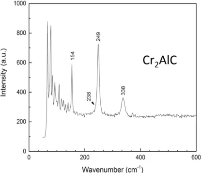
displacements corresponding to the Raman active optical modes are shown in Fig.1.8. These optical modes could be observed in the Raman spectrum of Cr2AlC (Fig.1.9). Although it has
four peaks, the Eg and one of the E2g modes overlap. Therefore, only three distinct sharp peaks
could be observed at approximately 150.9, 246.3 and 339.2 cm-1. Except Cr
2AlC, most
other211 phases, such as V2AlC and Ti2AlC, exhibit four distinct peaks in their Raman
24
Figure 1.8. Vibration modes of the V-Al bonds corresponding to the four peaks of the Raman spectrum of V2AlC, as obtained by Spanier et al.[55]
Figure 1.9. Raman spectrum of Cr2AlC single crystal with the laser beam parallel to the 𝑐 axis
(wavelength𝜆 = 514.532 𝑛𝑚)
For the 312 phases, there are seven Raman-active optical modes (2Ag+2Eg+3E2g) and
33 total optical modes. However, in experimental measurements, only six active modes could be evidenced [56-58](Fig.1.10). Furthermore, the 413 structure shows 10 Raman-active optical modes (3Ag+3Eg+4E2g). Similarly, to the previous phases, there are two overlapping vibration
25
1.4 Physical properties
The study of the main physical properties of the MAX phases has been extensively developed since Barsoum discovered the pure MAX phase compounds in 1996. Here, we focus on particular features that could reveal to be significant parameters for potential applications.
1.4.1 Hardness
Different with the nitrides and carbides with MX stoichiometry, the MAX phase compounds are relatively soft and elastic. They exhibit a better tolerance to damage. As the MAX phase compounds combine the properties of metals and ceramics, they are softer than most structural ceramics and harder than the majority of metals.
The first investigation of MAX phase hardness was performed in 1972 [8]. Some isolated, small single crystalline platelets of Ti3SiC2 synthesized by chemical vapor deposition
with sizes around 10µm, allowed the first analysis of mechanical anisotropy. The hardness along the c axis was found to be much higher than other orientations. Then subsequent work confirmed this result, and it was further proposed that the hardness is a function of indentation load. When the indenter load increases from 10 to 100 g, the Vickers hardness of Ti3SiC2 decreases
from 1900 to 600 kg/mm2. It finally reach a constant value of 600 kg/mm2 in the range of 100 g to 1 kg
load [9].
Based on all available hardness studies of MAX phase compounds, we can point out some conclusions:
1. The Vicher hardness Hv increases with decreasing load. It is not measurable below a certain lower limit value because of a lack of any trace of observable indentation [59,60].
2. Hv is dependent on grain size. The finer grain size results in a higher hardness. 3. The grain size also influences the coefficient between the hardness Hv and the load. The hardness of finer grained material will decrease more slowly than a coarser one with an increasing load.
1.4.2 Fatigue resistance
Fatigue test is one of the fundamental tests for mechanical applications. It determines the service life and whether the material is available and suitable for some particular use. Hence
26
the fatigue resistance largely limits the application range of the material. The investigation of MAX phase compounds on fatigue resistance is a main aspect as well. The estimation is generally divided into two aspects: observation of long cracks and short cracks, which determines the materials’ behavior in different conditions.
The damage associated with cyclic loading in many ceramics is generally attributed to cycle -dependent frictional wear at grain bridging sites. As such, ceramic microstructures designed for high damage tolerance are generally more prone to cyclic fatigue degradation, a fact that has been well discussed for a lot of ceramic composites [61].
The testing of long cracks reveals that the threshold and the stress intensity range factor ΔK of MAX phases are comparatively higher than those of conventional structural ceramics and some metals [62,63]. ΔKis given by:
ΔK= ξ(σmax-σmin)√𝜋𝑎
and where σmax and σmin are the maximum and minimum stress applied. a is flow size
The crack growth rate is strong function ΔK[64]. For example, for Ti3SiC2 sample, the
fatigue threshold and ΔKth are some of the highest values ever-observed in monolithic,
non-transformation ceramics.
In the investigation of short crack test in polycrystalline Ti3SiC2 [63], the result shows
that the crack growth rates under cyclic fatigue are obviously faster than those under static one. This is valid for most other MAX phase compounds. Generally the crack growth rates are a stronger function of maximum stress intensity Kmax than the stress intensity range factor ΔKth.
However, as the conclusion are based on a few studies, further work is required, especially if the MAX phase compounds are to be applied in the domain which requires strong fatigue resistance.
1.4.3 Damage tolerance
Damage tolerance is one of the key parameters for material applications, especially for the structural ceramics. It is usually assessed by pre-indenting the tensile surface of the bent bars with Vickers indentations made at increasing indentation loads.it is also intimately related to the ability of the MAX phases to contain and confine the extent of damage to small areas around the indentations by plastic deformation. Based on the available studies, the following conclusions can be given:
27
1. The post-indentation flexural strength are considerably less dependent on the indentation loads than typical structural ceramics [64].
2. Similar to other structural ceramics, the damage tolerance of coarse grain microstructures is superior to that of their finer-grained counterparts [65,66].
1.4.4 Machinability
In this last section related to mechanical properties, we will account for a parameter crucial for material applications: machinability. Here, most notable is the well known fact that ceramic materials are not machinable. In contrast, the MAX phase compounds are quite easily machinable with conventional tool steels or even manual hacksaws. It is very significant to mention that this ability doesn’t occur by plastic deformation, as in the case of metals, but rather by the breaking off of small microscopic platelets [67]. In that respect, they are not similar to other machinable materials. The MAX phase compounds don’t machine as one scope ice cream, but rather as in shaving ice [68]. Except for Be and Be-alloys, the MAX phases have some of the highest specific stiffness values for readily machinable solids.
Machinability of the MAX phases has not been sufficiently investigated. For example, Hwang et al. compared the cutting resistance of Ti3SiC2 to that of a middle-carbon steel, SM45C
[69]. The values of the main forces measured during the machining of Ti3SiC2 were much lower
than those of SM45C. After machining, the surface roughness of the Ti3SiC2 was lower than
that of SM45C as well. However, the damage to the tool used for machining the middle carbon steel was less than the damage to those used for Ti3SiC2 [70].
1.5 Chemical properties
Chemical reactivity is at the heart of this thesis, including chemical resistance and potentially useful chemical transformations. In the following three chapters, we will present the performance of MAX phase compounds, focusing on Cr2AlC, under conditions of corrosive
solution and gas. Here we give an overview of the chemical stability of MAX phase compounds in common acids and bases.
28
In general, the MAX phase compounds inherit the merits of ceramic including corrosion resistance. The corrosion behaviors vary depending on the composition. In many cases, the starting step is the extraction of A atoms from the structure into the surrounding media, leaving behind MX binary compounds. Hence, how the A atoms diffuse out and what are the left structures are attractive issues, and this work focuses on some of them. If A elements are not soluble in the surrounding media, the MAX phase should be stable.
Aggressive molten salt with oxygen can oxidize the MAX phase and dissolve it in the solution. They can transform the nano-lamellar structure into a 3D rock salt structure [71-74]. If the oxides of A element are insoluble in the molten salt, the phase can stay stable. Most MAX phase compounds are rather stable in common acids and bases. Table 1.3 gives a summary of Ti3SiC2 behavior in common acids and NaOH. It is worth noting that Ti3SiC2 is not stable in
HNO3 and HF. The corrosion resistance crucially depends on the oxide layer formed on the
surface. In chapter 4, the roles played by different A elements are summarized and compared, indicating appropriate conditions of applications for different phases. The mechanism of oxidation using HNO3 is similar to the one with oxygen-containing molten salts [71-74], which
can oxidize the MAX phase and dissolve it in the solution. Different MAX phases show different behaviors with respect to oxidation conditions, and we will see in chapter 2 that Cr2AlC is quite stable in H2O2 after several days, whereas V2AlC reacts when put in the same
conditions.
29
Sensitivity of the Al-based phases to HF exposure has attracted a lot of interest, as it can be put to good use to produce 2 dimensional binary compounds called MXenes. The latter are presented in the next section.
1.6 Mxenes
At elevated temperature, as the M-A bonds are weaker than M-X bonds, MAX phases selectively lose the A element in vacuum [81], in molten salts [71,72] and in some molten metals [73]. Besides, the high temperature induces de-twinning of the MX layers and turns them into a 3D MX rock salt structure [72,74]. Indeed, the M-A bonds are of a purely metallic nature while the M-X bonds are ionic, metallic and covalent. Unfortunately, in this high temperature decomposition, MX layers lose their layered structure to adopt that of gemstones, which makes them useless. As shown later in this work, MAX phase compounds can also lose both the M and A elements in the strong etchant H2+Cl2 gas at high temperature, and are transformed into
MX binary compounds.
1.6.1 Synthesis
In 2011, Naguib et al. successfully transformed MAX phases into 2D dimensional layers which they named MXenes [82]. For the first time, this transformation avoided to turn the mother phase into a compound with 3D rock salt structure as in refs [71-74,81]. They reported the synthesis of MXene Ti3C2 from Ti3AlC2 through the use of HF at room temperature. The
process and morphology of Ti2C are shown in Fig.1. According to this study, the HF etching
method is expected to be successful for several MAX phases except for MXenes phases that are not stable in the etchant solution. Until now, Ti3C2, Ti2C, Nb2C, V2C, Ti3CN, (V0.5Cr0.5)3C2
[74,82-84] etc. have been successfully obtained. In 2015, Naguib et al. succeeded in exfoliating Ti3AlC2 to form Ti3C2 using a mixture of LiF, and HCl [82]. The obtained material was tested
as a lithium ion battery electrode, and was shown to be more efficient than the same material obtained by HF etching. Presently this technic is only feasible with Ti3SiC2.
The samples are necessarily prepared in the form of powder. A very few microns are considered as the effective grain size for HF treatment. Synthesizing large size MXenes from MAX phase single crystals is therefore a challenge we started to attempt in this work. It will
30
be noted that the transformation kinetics of the MAX phases is an important factor to consider for the synthesis of MXenes from large crystals of MAX phases. Indeed, for very fine powders, the time spent in the solution ranges from 2h to 8h, whereas it can be imagined lasting several days for crystals of a size close to the centimeter [71].
The production of MXenes from the MAX phases is commonly carried out in HF hydrofluoric acid or NH4HF2. The associated reactions are respectively given below [74]:
Mn+1AlXn + 3HF = AlF3 + Mn+1Xn + 1.5H2 and
Mn+1AlXn + 3NH4HF2 = (NH4)3AlF6 + Mn+1Xn + 1.5H2
The etching of MAX phases by HF is shown to be anisotropic: it preferentially occurs along the ab plane [83]. According to the reaction above, the etching preferentially breaks the M-A bonds and extracts A atoms from the structure, leaving MX layers. The 2D MXenes is significantly more important than the 3D rock salt. Hence, the idea of etching is to eliminate element A without destroying the M-X bonds. The choice of the concentration, time and temperature of the acid solution is therefore essential. In the reaction, stirring may be not necessary, but it can accelerate the kinetics. A higher temperature substantially accelerates the reaction rate. In chapter 2, we will study the concentration limit of the reacting agent. For a fast etching, the concentration of HF cannot be less than 48%, while a low concentration could lead to a exponential growth of etching time. During the selective etching, the element A is replaced in the structure by the elements F, O or OH. Consequently, the MX layers are no longer interconnected by metallic bonds but by Van der Waals interactions between the new side groups, which induces their delamination [84,85]. Blocks of MX layers can therefore be easily separated from one another after ultra-sonication, as shown in Fig. 1.12.
Figure 1.12. (a) Process of synthesis MXene of by attacking a MAX phase in HF and then using ultrasound [71] (b) SEM image of obtained Ti2C by HF etching [83]
31
The reactions associated with the new terminations are given below [74]:
Mn+1Xn + 2H2O = Mn+1Xn(OH)2 + H2 and
Mn+1Xn + 2HF = Mn+1XnF2 + H2
A representation of one of the configurations is shown in Figure 1.13:
Figure 1.13. Arrangement of MXenes (left) and MXenes terminated by OH (right) [86]
However, the synthesis process in NH4HF2 often involves the intercalation of N2H4
between the layers of MXenes in the form of an independent monolayer structures. In addition, undesired phases may be formed during this synthesis method. For example, TiOF2 phase was
detected by X-rays when Ti3C2 was extracted from Ti3AlC2 by HF [81].
The MX sheets in MXene are interleaved with Van der Waals bonds or hydrogen bonds instead of M-A bonds in MAX phases [85] (Figure 1.14). After etching, the structure becomes loosely bonded, resulting in an accordion-like structure as for exfoliated graphene (Fig.1.12). The usually obtained MXene is formed of a few layers, which we called few-layer MXene (FL-MXene). Furthermore, the A element is probably replaced by various surface terminations. Hence, the MXene chemistry is rather Mn+1XnTx, where T denotes O, OH or F atoms.
The MAX phase transformation into MXene could lead to the attenuation or disappearance of all but (000l) peaks in the X-ray diffraction patterns. In the result for Nb2AlC
shown in Fig.1.15, the (000l) is the only peak observed. The peak intensity is enhanced because the sample in the literature is cold pressed [84]. Besides, as ab plane is unchanged, corresponding peaks are not broadened. However, XRD cannot quantify the unreacted MAX phase fraction. Therefore, we use EDS to analyze the element to access the actual percentage.
32
It is noted that this method will overestimate the fraction of conversion because the Al-containing salt, product of the exfoliation reaction, can still be present in the structure and be considered as unreacted part if the MXene is not completely washed and purified.
Table 1.4 is the summary of reported HF etching conditions for different MAX phase compounds with the correspondent c lattice parameter. The required etching time is dependent on the sample size, temperature, HF concentration and stirring condition. Therefore, reducing the particle size could help the reaction time decreasing from 90h to 8h [84]. It demonstrates from another aspect that for a large single crystal, it should be much longer than 90h. According to Naguib et al. [74], long etching times could result in the formation of defects such as deep holes that could accelerate the reaction rate while it could break the sample into pieces.
The loss of A element can be roughly assessed by measuring the weight before and after etching, rinsing, and drying of the samples. The result can be overestimated by the extraction of M atoms. Furthermore, it may be flawed by intercalation phenomena or if the drying of the samples is not complete.
In terms of the chemical resistance, the value n plays an important role. In general, a high n could result in a higher resistance and more stable MAX phases and MXenes [86], which could influence the reaction rate. Accordingly, the reaction design should take this factor into account.
Until now, most MXenes have been obtained from carbides, not from nitrides. It is noted that the calculated cohesive energies of Tin+1Nn from Tin+1AlNn are less than those of Tin+1Cn
from Tin+1AlCn [88]. The former has a higher formation energy and the latter results in a lower
chemical stability. Hence the bonds between Al and C are weaker than that of Al and N, which require more energy for extraction for Al-N bonds[88]. Another possibility is that the nitride MXene is not stable in HF and soluble in the solution.
33
Figure 1.15. XRD pattern of Nb2AlC before and after HF etching [89]
Table 1.4. Etching condition and c-lattice parameters for Mxene synthesis from MAX phases with the mother MAX phase c values
1.6.2 Structure
MX sheets of a few nanometers in thickness (two-dimensional character), with hexagonal structure, are thus recovered with the X atoms situated on the octahedral sites of the mesh formed by the element M. It is important to note that once the MX sheets are separated, they have T-termination elements at their surface that occupy the empty sites left by the element A [81] (Fig.1.16).
34
Figure 1.16. Schematic of the exfoliated Ti3AlC2 forming two OH-terminated MXene layers Model [74]
Thus, the MXene sheets are commonly referred to as Mn+1XnTx, with the T ending group
possibly being OH, F, O and H. There are various possible arrangements of the T group on the MX structure conferring different dielectric and chemical properties to the material. The nature of the T group and their surface arrangement are not controllable at present.
The first MXene structure model calculated by DFT method, was Ti3C2 layers
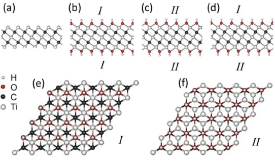
terminaed with OH groups. The real structure could be more complicated than the simple simulation model because of mixed termination and incompletely converted structure. Besides, water molecules could interleave in the structure, leading to a larger c lattice parameter [84]. Then DFT predicts two energetically favorable orientations of T groups in Ti3C2T2 [90, 91],
shown as configurations I and II in Fig. 1.17. In type I, the T groups are located above the hollow sites among three neighboring C atoms and the T groups point directly toward the Ti(2) atoms on both sides of the M3X2 layers. In type II, the T terminations are located above the C
atoms on both sides of the M3X2 layers. The mixed structure of I and II is commonly considered
as configuration III, where one side is I and the other side is II.
The relative stability of structure of different Ti3C2F2 and Ti3C2(OH)2 configurations
was estimated by DFT energy calculations. Briefly, the stability order is I >III>II. It demonstrates that both termination F and OH are more likely to adopt configuration I. hence, the low structural stability is ascribed to steric repulsion between T groups and the underlying C atoms [92]. Another configuration where terminations are linked to and located above Ti(1) atoms of MX layer is demonstrated to be unstable and easily transformed into the other two configurations.
35
Figure 1.17. Configurations of functionalized MXenes with different arrangements of the surface atoms: side views of a) bare Ti3C2, b) I-Ti3C2(OH)2, c) II-Ti2C(OH)2, and d) III-Ti3C2(OH)2 ; e,f) top
views of I-Ti3C2(OH)2 and II-Ti3C2 (OH)2 . As configuration III is a mixture of I and II, its top view is
not shown. [90]
1.6.3 Properties
2D MX layers present excellent characteristics in terms of electrical and thermal conductivity and sometimes show better properties than their mother phases. Besides, the MXenes have a hydrophilic character.
MXenes can be considered as 2D dimensional “separated” MAX phase monolayers. So, they inherit corrosion resistance from the mother phases. The terminations could influence the electronic structure, which corresponds to a metallic monolayer with a high electron density at the Fermi level (Ef) [91-94]. In the mother phase, MAX phase, N(Ef) is dominated by M3d
orbitals and the valence states below Ef group are composed of two sub bands. Sub band A near Ef is made of hybridized Ti 3d-Al 3p orbitals and sub band B below Ef between -10ev and -3ev which is made of hybridized Ti 3d-C 2p and Ti 3d-Al 3s orbitals. In other words, sub-band A is due to Ti-Al bonds, and sub band B is the source of Ti-C bonds. The exfoliation of A layer could lead to the redistribution of Ti 3d states from missing Ti-Al bonds into delocalized Ti-Ti metallic bond states around the Fermi energy in Ti2C. Therefore, N(Ef) in MXene is much
36
The high Ef value could lead to a magnetic instability. If the Stoner criterion is
satisfied, the MXenes should be magnetic [91-95]. However, the bare surface is a theoretical state. The real MXenes with terminations could eliminate the magnetism due to p-d bonds between T groups and M atoms, resulting in a partial depopulation of the states around the Fermi energy.
Surface termination also influences the possible existence of a bandgap. Although most MXenes should be metallic conductors, a semiconducting behavior is predicted for Ti3C2F2 and Ti3C2(OH)2, with bandgaps of 0.1eV and 0.05eV respectively [96]. This could be
ascribed to the tuning of the electronic structure by varying the T groups. Then this would confirm that the electronic structure is not only dominated by the surface termination type but also by the orientation relative to the MX layer. Sometimes, this could result in a semi-conducting state [96].
The expected mechanical properties of MXene are rather interesting since the M-X bonds are very strong bonds. In addition, these good properties are expected to be preserved at very high temperatures. DFT simulations allowed to estimate an elastic constant of the order of 300GPa for z-axis stress and Ti3C2(OH)2[83].
MXenes are also expected to be more rigid than their mother MAX phase since the M-A bonds energies are much lower than that of the M-X bonds (Table 1.5)[97]. The expected elastic constants for MXenes are lower than for graphene. However, the flexural rigidity of MXenes seems better than that of graphene. This is explained by the fact that this stiffness behaves at t3 , with t the of thickness of the layer, and that the Mxenes are constituted by at least
three atomic layers against one fore graphene. Moreover, this thickness and therefore the flexural rigidity can be improved by playing on n in Mn+1Xn.
Table 1.5. In-plane elastic constant (c11) of different MXenes with the corresponding a lattice parameter
and DOS at Ef by first principles calculation [97]. The values in brackets in column 3 are c11 of
37
1.6.4 Potential applications
Since the appearance of graphene in 2000, two-dimensional materials are the subject of particular attention. The MXene family is of great interest for two-dimensional materials because of its versatility and the diversity of its members.
Indeed, because graphene is composed solely of carbon, by playing on the elements M and X of the 2D sheets of metal carbide, or by choosing the number of layers n, a vast variety of properties can potentially be obtained.
Due to their expected electrical, optical and mechanical properties, these materials can potentially be used for many applications such as supercapacitors, sensors, electronic devices, catalysts [98-100] for the chemical industry, conductive polymer reinforcements or electrochemical energy. More and more research has been done on these applications. Here we give an overview of these fields of application, based on a recent review by Barsoum et al. [81].
Energy storage
DFT simulations have made possible to predict the intercalation process of Li in Ti3C2
38
environment, the formation of Ti3C2Li2 makes possible to store Li-ions. For Ti3C2, similarly as
for Ti3C2F2 and Ti3C2 (OH)2, the Li atom is placed above the carbon atom. A charge transfer
takes place between Ti3C2T2 and Li via a Coulomb interaction. The theoretical capacity of the
sheets of Ti3C2, Ti3C2F2 and Ti3C2(OH)2 would be respectively 320, 130 and 67 mAh/g [91].
Moreover, these calculations predict that the Ti3C2 sheets are better anodes than the current
phase TiO2. Indeed, they are better conductors (metallic character), have a lower open circuit
voltage, better Li storage capacity, and a high cycle rate. Moreover, the diffusion barrier of Li in Ti3C2 amounts to 0.07 eV against more than 0.3 eV for TiO2. This means that Ti3C2 could
take on higher charging and discharge rates, making them promising for high-power batteries. It has been estimated that the larger n is, the more atomic layers will be in per sheet, the better the storage of Li ions will be.
In addition, the ability of Ti3C2 to withstand high cycle rates makes them suitable
candidates for hybrid cells, asymmetric and non-aqueous energy storage devices, which combine high-density LiB energy and high-power density EDLC (Electrical Double Layer Capacitors) [103].
Such supercapacitors have been tested with an activated carbon cathode and an anode of Ti3CT2 with KOH as the electrolyte. With a current of 1A/g, the reversible capacity of the
supercapacitor was 51 F / g, which is greater than that of the best EDLCs[104].
Finally, many other applications may be provided for these multilayer materials. Among them are the multivalent ion batteries (Mg2+ or Al3+ intercalation). Very recently, Xie et al.
[105] have used Ti3C2Tx as a support material for Platinum Nano-particles in order to
manufacture a fuel cell. They have thus demonstrated that the Pt / Ti3C2Tx combination is more
durable and more stable than the conventionally used Pt / C pair. After 10,000 cycles, the Pt / Ti3C2Tx catalyst lost 15.7% of its active electrochemical surface of Platinum, while the Pt / C
electrode lost 40%.
Electrical devices
The two-dimensional morphology of MXenes and their excellent electrical conductivity make them attractive for electronic applications, especially when combined with other 2D semiconducting materials such as MoS2 [106]. In these hybrid systems, the MXene sheets can
be utilized as a conductive interface. They can also be used to modify the electrical properties of the other 2D materials with which they are in contact. At present, no experimental studies have confirmed these hypotheses; only a few DFT simulations are able to predict the
![Figure 1.3. HRTEM image of a basal plane Stacking fault in Ti 3 SiC 2 . The viewing direction is [11- [11-20,49]](https://thumb-eu.123doks.com/thumbv2/123doknet/14528783.723254/21.892.300.598.453.795/figure-hrtem-image-basal-plane-stacking-viewing-direction.webp)
![Figure 2.5. Raman spectrum of very orderly pyrolytic carbon. The wavelength used is 633 nm [33]](https://thumb-eu.123doks.com/thumbv2/123doknet/14528783.723254/75.892.211.680.103.388/figure-raman-spectrum-orderly-pyrolytic-carbon-wavelength-used.webp)