HAL Id: tel-03137899
https://tel.archives-ouvertes.fr/tel-03137899
Submitted on 10 Feb 2021HAL is a multi-disciplinary open access archive for the deposit and dissemination of sci-entific research documents, whether they are pub-lished or not. The documents may come from teaching and research institutions in France or
L’archive ouverte pluridisciplinaire HAL, est destinée au dépôt et à la diffusion de documents scientifiques de niveau recherche, publiés ou non, émanant des établissements d’enseignement et de recherche français ou étrangers, des laboratoires
optical packet switching node design in optical networks
Maria Freire Hermelo
To cite this version:
Maria Freire Hermelo. Amplifier control using machine learning and coloured optical packet switching node design in optical networks. Optics / Photonic. Institut Polytechnique de Paris, 2020. English. �NNT : 2020IPPAS024�. �tel-03137899�
NNT
:
2020IPP
AS024
and coloured optical packet switching
node design in optical networks
Th `ese de doctorat de l’Institut Polytechnique de Paris pr ´epar ´ee `a T ´el ´ecom SudParis ´
Ecole doctorale n◦626 ´Ecole doctorale de l’Institut Polytechnique de Paris (EDIPP)
Sp ´ecialit ´e de doctorat : R ´eseaux, informations et communications
Th `ese pr ´esent ´ee et soutenue `a ´Evry, le 16/12/2020, par
M
ARIA
F
REIRE
-H
ERMELO
Composition du Jury :
Yves Jaouen
Professeur, T ´el ´ecom Paris Pr ´esident
Nicola Calabretta
Professeur associ ´e, Eindhoven University of Technology Rapporteur Bruno Fracasso
Professeur, IMT Atlantique Rapporteur
Ramon Casellas
Chercheur Senior, CTTC Examinateur
Christine Tremblay
Professeur, ´Ecole de Technologie Sup ´erieure Montr ´eal Examinateur Catherine Lepers
Professeur, T ´el ´ecom SudParis Directeur de th `ese
Antoine Lavignotte
Maˆıtre de Conf ´erence, T ´el ´ecom SudParis Co-directeur de th `ese Dominique Chiaroni
Mots cl ´es : Amplificateurs `a fibre dop ´ee `a l’erbium, apprentissage machine, r ´eseaux optiques, commutation
de paquets optiques color ´es, excursion de puissance optique, qualit ´e de transmission
R ´esum ´e : Le d ´ebit de donn ´ees et la consommation
d’ ´energie sont les principaux d ´efis auquels doivent faire face les r ´eseaux optiques. Afin de r ´eduire la consommation d’ ´energie, les r ´eseaux op ´erateurs de transport optiques bas ´es sur le concept de com-mutation de circuits optiques (OCS), deviennent op-tiquement transparents, r ´eduisant les conversions optique/ ´electrique (O/E) et ´electrique/optique (E/O). Pour faire face `a l’augmentation du d ´ebit de donn ´ees, on utilise des formats de modulations complexes et la technique de multiplexage en po-larisation et on ´economise le spectre des fibres optiques en consid ´erant une grille en longueurs d’onde plus flexible que la grille fixe ITU-T WDM. On d ´eveloppe des transpondeurs flexibles capables de s ´electionner diff ´erents formats de modulation et longueurs d’onde; on d ´eveloppe ´egalement des multiplexeurs optiques d’insertion/extraction reconfi-gurables (ROADMs) bas ´es sur des commutateurs s ´electifs en longueur d’onde (WSSs).
Ces r ´eseaux flexibles prennent ´egalement en compte un trafic plus dynamique. Dynamisme et flexibilit ´e im-pactent fortement les ´equipements des r ´eseaux op-tiques, y compris les nœuds optiques d’un point de vue couche physique et couche de contr ˆole. Lorsque des canaux ou demandes sont ajout ´es et/ou extraits, l’excursion de puissance optique des amplificateurs `a fibre dop ´ee `a l’erbium (EDFAs) varie temporelle-ment ce qui implique qu’elle doit ˆetre contr ˆol ´ee dyna-miquement. Dans ce contexte, le concept de r ´eseau d ´efini par le soft (SDN: Software Defined Network) prend tout son sens et l’introduction des techniques d’apprentissage machine (ML) permet d’entrevoir une aide au concept de SDN pour la gestion et le contr ˆole dynamique des r ´eseaux optiques.
Dans la premi `ere partie de ce travail de th `ese, nous ´etudions l’excursion de puissance optique dans les r ´eseaux de transport optiques dynamiques. Afin d’en att ´enuer les effets ind ´esirables, nous introduisons et
mettons en œuvre un module de pr ´ediction et de pr ´e-compensation de l’excursion de puissance en utili-sant les m ´ethodes ML. Comme les alt ´erations de la couche physique (PLIs : Physical Layer Impairments) s’accumulent le long du chemin optique entre les noeuds source et destination de r ´eseau, nous asso-cions `a l’excursion de puissance optique le rapport si-gnal/bruit optique (OSNR: Optical Signal to Noise Ra-tio) et le taux d’erreur binaire (BER: Bit Error Rate), afin d’estimer la qualit ´e de transmission (QoT: Quality of Transmission) de nouvelles configurations de ca-naux. Ensuite, en utilisant l’approche d’apprentissage par renforcement (RL), nous attribuons un format de modulation et une longueur d’onde aux diff ´erents ca-naux de fac¸on automatique afin de r ´eduire la proba-bilit ´e de blocage des demandes entrantes dans les nœuds optiques.
Dans la deuxi `eme partie de ce travail de th `ese, nous pr ´esentons notre contribution en tant que partenaire du projet ANR N-GREEN. Le principal objectif de N-GREEN est de proposer une nouvelle g ´en ´eration de routeurs peu consommateurs en ´energie en consid ´erant une architecture de r ´eseau. Dans ce projet, nous abordons une architecture de r ´eseau bas ´ee sur la commutation optique de paquets co-lor ´es (OPS: Optical Packet Switching) en rupture avec celle consid ´er ´ee dans la premi `ere partie de cette th `ese. Dans le cadre de ce projet, nous avons caract ´eris ´e exp ´erimentalement un commutateur op-tique 2 × 2 bas ´e sur des amplificateurs opop-tiques `a semi-conducteurs (SOAs). Cette caract ´erisation nous a permis de valider un r ´eseau en anneau constitu ´e de 10 noeuds en cascade. En envisageant une configuration de commutateur 16 × 16, la ca-ract ´erisation exp ´erimentale, dans des configurations `a canal unique et WDM, laisse entrevoir des possibi-lit ´es int ´eressantes pour la transmission de donn ´ees `a tr `es haut d ´ebit.
Keywords : Erbium doped fiber amplifiers, machine learning, optical networks, coloured optical packet
swit-ching, optical power excursion, quality of transmission
Abstract : Data rate and energy consumption are the
major concerns in optical networks. In order to reduce energy consumption, transport operator networks ba-sed on optical circuit switching (OCS) concept, are be-coming optically transparent, reducing optical to elec-trical (O/E) and elecelec-trical to optical (E/O) conversions. To face data rate increase, complex modulation for-mats and dual-polarization systems are considered and fiber spectrum is saved using network resources in a more efficient way, giving rise to a flexible fre-quency grid. Flexible transponders are developed to tune modulation formats and wavelengths and recon-figurable optical add/drop multiplexers (ROADMs) ba-sed on wavelength selective switches (WSSs) are stu-died.
Flexible networks consider also a more dynamic traf-fic. Dynamism and flexibility lead to a deep trans-formation of the optical networks, including optical nodes, from both physical and control layer point of view. When channels are added and/or dropped, op-tical power excursion from erbium doped fiber ampli-fiers (EDFAs) has to be controlled dynamically. In that context, software defined networking (SDN) assisted by machine learning (ML) techniques is envisaged as promising candidate for the management and the dy-namic control of optical networks.
In this context, in the first part of our PhD work, we deal with optical power excursion in dynamic optical transport networks. In order to mitigate undesirable
effects, we introduce and implement power excursion prediction and pre-compensation module using ML methods. As physical layer impairments (PLIs) ac-cumulate along the path, we consider optical power excursion together with optical signal to noise ratio (OSNR) and bit error rate (BER), to estimate quality of transmission (QoT) of unseen channel configura-tions. Afterwards, using a reinforcement learning (RL) approach, we establish an autonomous impairment aware modulation format and wavelength assignment procedure, and we show that this permits to reduce the blocking probability of the incoming demands in optical nodes.
In the second part of our PhD work, in the context of the N-GREEN project from the French national agency of research, we address a disruptive network architecture based on coloured optical packet swit-ching (OPS). The main objective of N-GREEN is to propose a new generation of energy efficient routers. In the N-GREEN project, we perform the experimen-tal characterization of an optical 2 × 2 switch based on semiconductor optical amplifiers (SOAs). This charac-terization leads to the proof of concept of a ring net-work with 10 nodes in cascade. Envisaging a 16 × 16 switch configuration, the experimental characteriza-tion, in single channel and WDM configurations, unveil interesting possibilities for the transmission of ultra-high data rates.
I would like to thank the following people without whom my PhD work would not have been completed.
My supervisor, Catherine Lepers, for her continuous guidance and support during the whole PhD process, research and writing. Her invaluable insights have been decisive in the develop-ment of the work presented here. Without her motivation and enthusiasm, this PhD would not be possible.
My co-supervisor, Antoine Lavignotte, always supportive and willing to assist in each stage of the work. His thoughtful comments and recommendations have been of great importance to complete this work.
The reviewers, Nicola Calabretta and Bruno Fracasso, for reviewing my manuscript and helping to greatly improve it.
All the jury members, Yves Jaouen, Christine Tremblay, Ramon Casellas and Dominique Chiaroni for accepting to evaluate my work, providing fruitful comments and suggestions. Djamel Amar, Franck Gillet and Sébastien Mansfeld, for advising and collaborating in the first steps of this research project.
Christine Tremblay and Dipankar Sengupta, for their patience, always willing to help in any possible way: experimental measurements, meetings, reviews... Their knowledge and experience have been of incredible valuable.
All the people involved in the ANR N-GREEN project, especially Atchutananda Surampudi, Alexandre Shen, Mengdi Song, Cédric Ware, Yves Jaouen, Eloise de Carvalho Rodrigues, Do-minique Chiaroni, not only for their help in the experimental work but also for sharing their knowledge.
All the people that indirectly contributed to this work: Nicolas Montes and Loic Duboquet for their help in software subjects and Ydalia Garcia, Patricia Fixot, Sandra Gchweinder, Zahia Zendagui and Veronique Guy for facilitating all required administrative procedures.
The people from the RST and EPH departments, especially my colleagues for their support, always creating a great atmosphere: Nesrine, Franklin, Nazhatul, Marwan, Souha, Mariana, Mohammed, Ana, Fabien, Jose.
My family and friends for their understanding and encouragement. And specially, my fiance for his unconditional support.
Abstract (English/Français) i
Acknowledgements v
Acronyms xi
List of figures xiv
List of tables xix
Introduction 1
1 Research context 5
1.1 Network Evolution . . . 7
1.2 Optical node evolution . . . 8
1.3 SDN decision aided with machine learning methods . . . 11
1.4 Optical packet switching vision in the N-GREEN project . . . 15
1.5 Summary . . . 17
I Machine learning techniques for physical layer control 19 2 Optical power excursion prediction and precompensation 21 2.1 Machine learning techniques overview . . . 21
2.1.1 Fundamentals . . . 22
2.1.2 Algorithms: Supervised, unsupervised and reinforcement learning . . . 25
2.2 Optical power excursion challenge . . . 36
2.2.1 Optical amplifier modules . . . 36
2.2.2 Optical power excursion problem in WDM systems . . . 38
2.2.3 State of the art of the technical solutions . . . 40
2.3 Experimental validation of an amplifier model . . . 44
2.3.1 Amplifier experimental characterization . . . 45
2.3.2 Amplifier model based on experimental characterization . . . 46
2.3.3 Model validation . . . 49
2.5 Optical power excursion precompensation based on reinforcement learning . . 53
2.5.1 Development of a reinforcement learning algorithm for precompensation 55 2.5.2 Evaluation of different reinforcement learning methods . . . 58
2.5.3 Experimental proof-of-concept of the reinforcement learning algorithm 67 2.6 Conclusions . . . 70
3 Impairment aware modulation format and wavelength assignment 73 3.1 State of the art of routing and wavelength assignment . . . 73
3.1.1 Traditional RWA formulation overview . . . 73
3.1.2 Impairment Aware RWA problem formulation . . . 75
3.2 Quality of transmission estimation models . . . 77
3.3 Impairment aware modulation format and wavelength assignment algorithm proposal . . . 81
3.3.1 Numerical setup . . . 82
3.3.2 Quality of Transmission estimation . . . 96
3.3.3 Reinforcement learning approach . . . 103
3.4 Fixed grid . . . 108
3.4.1 OSNR aware wavelength assignment . . . 109
3.4.2 BER aware wavelength assignment . . . 110
3.5 Flexible grid . . . 112
3.5.1 OSNR aware wavelength assignment . . . 112
3.5.2 BER aware wavelength assignment . . . 113
3.6 Conclusions . . . 114
II Coloured optical packet switching in the N-GREEN project 117 4 Experimental characterization of an SOA-based photonic integrated switch 119 4.1 Optical switching overview . . . 120
4.1.1 Future optical interconnections . . . 123
4.2 N-GREEN project . . . 123
4.2.1 WSADM . . . 125
4.2.2 Ultra-High Capacity WDM backplane . . . 126
4.2.3 Network scenarios . . . 126
4.3 Experimental characterization of the 2 x 2 N-GREEN switch . . . 127
4.3.1 Static characterization . . . 128
4.3.2 Dynamic characterization . . . 130
4.4 Conclusions . . . 137
Conclusions and perspectives 139
Appendix 145
A Neural networks 147
B RL Policy gradient algorithms 151
C Optical amplification 153 C.1 Light amplification . . . 154 C.2 EDFAs . . . 154 C.2.1 Gain characteristics . . . 156 C.2.2 Noise characteristics . . . 158 C.2.3 Gain dynamics . . . 158 C.3 SOAs . . . 160 C.3.1 Physical characteristics . . . 160 C.3.2 Gain characteristics . . . 161 C.3.3 Noise characteristics . . . 162 C.3.4 Gain dynamics . . . 163 D VPI software 165 E Conclusion (Français) 167 Bibliography 194
A2C Advantage Actor Critic.
A3C Asynchronous Advantage Actor Critic. AGC Automatic Gain Control.
ASE Amplified Spontaneous Emission. AWG Arrayed Waveguide Grating.
B2B Back-to-Back. BER Bit Error Rate.
BMRx Burst-Mode-Receiver.
CBR Case Based Reasoning. CC Current control.
CD Chromatic Dispersion.
CNN Convolutional Neural Network. CSI Channel State Information.
DCM Dispersion Compensating Module. DDPG Deep Deterministic Policy Gradient. DP Dual Polarization.
DP-MZM Dual Polarization-Mach Zehnder Modulator. DSO Digital Sampling Oscilloscope.
DSP Digital Signal Processing.
EDF Erbium Doped Fiber.
EDFA Erbium Doped Fiber Amplifier. EVM Error Vector Magnitude.
FDL Fiber Delay Line.
FEC Forward Error Correction. FF First Fit.
FF-Center First-Fit closest to the CENTER of the band. FF-L2H First-Fit from Lowest to Highest frequencies. FFT Fast Fourier Transform.
FWM Four-Wave Mixing.
GFF Gain Flattening Filter.
GMPLS Generalized Multi-Protocol Label Switching. GN Gaussian Noise.
HT Holding Time.
IA-RWA Impairment-Aware Routing and Wavelength Assignment. IAT Inter-Arrival Time.
IGN Incoherent Gaussian Noise. ILM Integrated Laser Modulator. ILP Integer Linear Programming. IPDR Input Power Dynamic Range. ISI Intersymbol Interference.
k-NN k-Nearest Neighbors.
LC Liquid Crystal.
LCoS Liquid Crystal on Silicon. LiNbO3 Lithium Niobate.
LP Linear Programming.
MEMS MicroElectroMechanical Systems. ML Machine Learning.
MPLS Multiprotocol Label Switching.
NF Noise Figure.
NLI NonLinear Interference. NN Neural Network.
O/E Optical to Electrical.
OADM Optical Add/Drop Multiplexer. OCS Optical Burst Switching.
OPS Optical Packet Switching. OSA Optical Spectrum Analyzer. OSC Optical Supervisor Channel. OSNR Optical Signal to Noise Ratio.
PC Polarization Controller.
PCA Principal Component Analysis.
PDME Polarization Division Multiplexer Emulator. PLC Planar Lightwave Circuit.
PLI Physical Layer Impairments.
PLZT Lead Lanthanum Zirconate Titanate. PMD Polarization Mode Dispersion.
POADM Packet Optical Add/Drop Multiplexer. PPO Proximal Policy Optimization.
QAM Quadrature Amplitude Modulation. QoS Quality of Service.
QPSK Quadrature Phase-Shift Keying.
RAM Random Access Memory. ReLU Rectified Linear Unit. RF Random Forest.
RL Reinforcement Learning.
ROADM Reconfigurable Optical Add/Drop Multiplexer. RWA Routing and Wavelength Assignment.
SCH Separate Confinement Heterostructure. SD-FEC Soft Decision Forward Error Correction. SDM Spatial Division Multiplexing.
SDN Software Defined Networking. SMF Single-Mode Fiber.
SNR Signal to Noise Ratio.
SOA Semiconductor Optical Amplifier. SPM Self-Phase Modulation.
SRS Stimulated Raman Scattering. SVM Support Vector Machine.
TRPO Trust Region Policy Optimization.
VOA Variable Optical Attenuator.
WDM Wavelength Division Multiplexing. WSADM WDM-Slotted Add/Drop Multiplexer. WSS Wavelength Selective Switch.
1.1 Evolution of commercial optical transmission systems . . . 6
1.2 Five physical dimensions to increase capacity . . . 6
1.3 Optical network architecture . . . 8
1.4 Wavelength blocker ROADM architecture . . . 9
1.5 PLC-ROADM architecture . . . 10
1.6 WSS based ROADM architectures . . . 11
1.7 ROADM colorless, directionless, contentionless architectures . . . 12
1.8 SDN-based optical network architectures . . . 13
2.1 ML examples. . . 23
2.2 Relationship between capacity and error. . . 24
2.3 ML techniques and their applications . . . 26
2.4 General NN diagram. . . 28
2.5 RL agent-environment interaction . . . 31
2.6 EDFA module architecture. . . 37
2.7 NN architecture used to predict maximal power excursion. . . 42
2.8 Amplifier power masks for gain and NF. . . 43
2.9 Simplified scheme of a double-stage amplifier. . . 45
2.10 Amplifier characterization: Experimental setup (Network Technology Lab) . . . 46
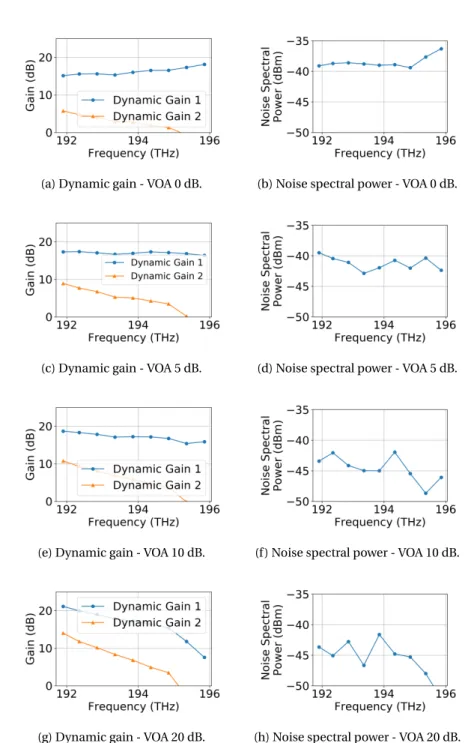
2.11 Dynamic gain curves and spectral noise power in CC mode . . . 47
2.12 Amplifier model validation: Experimental setup (Network Technology Lab) . . 49
2.13 Amplifier model validation: Simulation setup. . . 50
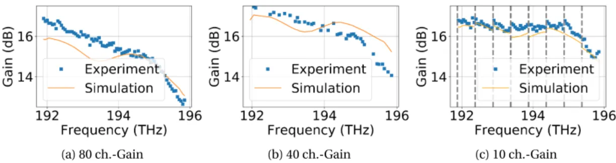
2.14 Gain for 80 channels, 40 random channels and 10 channels. . . 50
2.15 Gain difference for different input peak powers . . . 51
2.16 Optical power excursion prediction: Development diagram. . . 51
2.17 Optical power excursion prediction: Simulation setup. . . 52
2.18 Optical power excursion prediction: Dataset. . . 52
2.19 Optical power excursion prediction example . . . 53
2.20 Optical power excursion prediction: Accuracy . . . 53
2.21 RL approach for optical power excursion precompensation . . . 54
2.22 Power precompensation: Simulation setup. . . 56
2.24 Power precompensation: Simulation setup for algorithm comparison. . . 60
2.25 Power precompensation: Learning curves for 12, 24, 40 and random channels . 64 2.26 Power precompensation: Training time . . . 65
2.27 Power precompensation: Evolution for 12, 24, 40 and random channels . . . 65
2.28 Power precompensation: Histograms . . . 66
2.29 Power precompensation: Mean optical power . . . 66
2.30 Power precompensation: Valid wavelengths . . . 67
2.31 Power precompensation proof of concept: Experimental setup (Net. Tech. Lab) 68 2.32 Power precompensation proof of concept: Simulation setup. . . 68
2.33 Power precompensation proof of concept: Learning curve. . . 69
2.34 Power precompensation proof of concept: Evolution . . . 70
2.35 Power precompensation proof of concept: Power deviation . . . 70
2.36 Amplifier control in SDN-based optical network architecture . . . 72
3.1 Setup for impairment aware modulation format and wavelength assignment. . 83
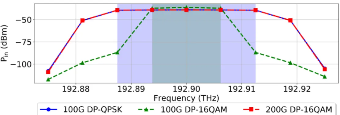
3.2 Input channel power measured in slices of 6.25 GHz bandwidth. . . 88
3.3 Output channel power measured in slices of 6.25 GHz bandwidth. . . 89
3.4 Output power excursion measured in slices of 6.25 GHz bandwidth. . . 89
3.5 Back-to-back simulation results . . . 92
3.6 OSNR for different input launch powers . . . 95
3.7 NN models for optical power excursion prediction. . . 99
3.8 NN models for OSNR classification. . . 99
3.9 NN models for BER classification. . . 101
3.10 RL approach impairment aware modulation format and wavelength assignment 104 3.11 Fixed grid: Example of obtained power excursion, OSNR and BER. . . 108
3.12 Fixed grid: Blocking probability comparison for OSNR aware algorithm . . . 109
3.13 Fixed grid: Channel assignment evolution for OSNR aware algorithm . . . 110
3.14 Fixed grid: Blocking probability comparison for BER aware algorithm . . . 111
3.15 Fixed grid: Channel assignment evolution for BER aware algorithm. . . 111
3.16 Flexible grid: Example of obtained power excursion, OSNR and BER . . . 112
3.17 Flexible grid: Blocking probability comparison for OSNR aware algorithm . . . 113
3.18 Flexible grid: Channel assignment evolution for OSNR aware algorithm . . . 114
3.19 Flexible grid: Blocking probability comparison for BER aware algorithm . . . . 114
3.20 Flexible grid: Channel occupation evolution for BER aware algorithm. . . 115
3.21 Modulation format and wavelength assignment in SDN-based architecture . . 116
4.1 Optical switching technologies . . . 122
4.2 Scheme of the POADM . . . 124
4.3 Scheme of the WSADM . . . 125
4.4 Scheme of the WDM backplane . . . 126
4.5 Image and scheme of the 2 × 2 switch . . . 128
4.6 ASE noise power for different bias current . . . 128
4.8 Static Characterization: Wavelength comparison . . . 130
4.9 Static Characterization: Polarization comparison . . . 130
4.10 Setup continuous mode single ch . . . 131
4.11 Dynamic Characterization continuous mode, single ch. . . 132
4.12 Dynamic Characterization continuous mode, single ch.: Constellations . . . 133
4.13 Setup continuous mode WDM . . . 133
4.14 Dynamic Characterization continuous mode, WDM: BER and EVM. . . 134
4.15 Setup packet mode single ch. . . 135
4.16 Setup packet mode WDM . . . 136
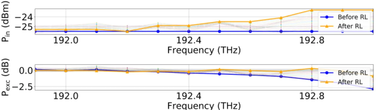
4.17 Dynamic characterization packet mode: Pr xvs. Pi n. . . 136
4.18 Dynamic characterization packet mode: BER vs. Pr x . . . 137
C.1 Amplifier gain comparison . . . 153
C.2 Interactions between photons and atoms . . . 154
C.3 Example of absorption and emission cross sections of Lucent HE980 EDF. . . . 155
C.4 Different EDFA architectures . . . 156
C.5 EDFA gain and spontaneous emission factor for different pump powers . . . 157
C.6 Power transients in an EDFA cascade . . . 159
C.7 SOA structure . . . 160
C.8 Typical SOA gain and ASE spectrum . . . 161
3.1 Summary of QoT estimation approaches based on ML techniques . . . 82 3.2 Considered data rate and modulation formats. . . 83 3.3 Simulated symbols and samples/symbol for each modulation and data rate. . . 86 3.4 Transmitter configuration. . . 87 3.5 OSNR and pre-FEC BER thresholds . . . 91 3.6 Fixed grid: Mean squared error optical power excursion regression. . . 98 3.7 Fixed grid: Accuracy OSNR classification. . . 100 3.8 Flexible grid: Accuracy OSNR classification. . . 101 3.9 Fixed grid: Accuracy BER classification. . . 102 3.10 Flexible grid: Accuracy BER classification. . . 103 3.11 Power excursion, OSNR and BER thresholds. . . 109 4.1 Comparison of commercial optical switching technologies. . . 123 4.2 Switch correspondence among SOA, input and output . . . 127 4.3 Dynamic Characterization continuous mode, single ch.: Summary . . . 132 4.4 Dynamic Characterization continuous mode, WDM: Wavelengths. . . 134 4.5 Dynamic Characterization continuous mode, WDM: Summary. . . 134 4.6 Parameters for packetized data . . . 135 4.7 WDM wavelengths used for dynamic characterization . . . 135 A.1 Error propagation . . . 150 C.1 Bandgap of some semiconductor compounds . . . 161
Year by year the number of internet users, devices and connections increase continuously [1]. Video streaming, web services, gaming, social applications and file sharing are some of the most hungry applications representing a large part of the global traffic [2]. Apart from high capacity, 5G wireless networks request low latency and precise synchronization [3]. All these factors shape the evolution of optical networks.
First generation of opaque optical networks was based on point-to-point links, where at each node, all the traffic had to undergo optical to electrical (O/E) and electrical to optical (E/O) conversions. All the intelligence of the network, routing and switching capabilities, resided in the electrical domain.
Second generation initiated the road towards transparency, reducing the network cost and improving its energy-efficiency [4], [5]. First, erbium doped fiber amplifiers (EDFAs) allowed to compensate fiber propagation losses in wavelength division multiplexing (WDM) systems avoiding O/E-E/O conversions. After, the introduction of optical add-drop multiplexers (OADMs) introduced the optical bypass concept, i.e. traffic for which the current node is not its final destination can pass-through the node, escaping again from unnecessary O/E-E/O conversions. This second generation has acquired intelligence, including an optical control plane, which permits to perform switching functionalities, usually based on an electrical control. Although current second generation, includes already reconfigurability capabilities, e.g. using reconfigurable optical add-drop multiplexers (ROADMs), it relies mainly on static traffic.
Third generation of optical networks is still under active development phase. Photonics community considers the circuit switching-based operation as fundamental in the optical systems currently in use. An interesting alternative discussed in the literature, although still immature due to optical buffering and optical signal processing issues, could be potentially based on optical packet switching (OPS) operation [6]. Presumably preserving optical circuit switching, third generation will be likely to be based on transparency, exploiting all-optical switching.
In order to answer to the high-capacity requirements imposed by the traffic, third generation is expected to grow on dynamism and flexibility. Under dynamic traffic conditions, where
channels are often added and dropped, dynamic reconfiguration capabilities allow for a more efficient use of the available spectrum [7]. Flexible optical networks, where instead of a fixed frequency grid of 50 GHz frequency spacing, a flexible frequency grid with 12.5 GHz frequency slots is considered, permit to assign a channel to any multiple of the fundamental slot, contributing to optimize the spectrum usage [8]. Furthermore, due to the independence of modulation formats and data rates given by the use of transparent nodes, flexible frequency grid can be combined with mixed line rates and different modulation formats, upgrading the network performance.
To exploit these capabilities, flexibility and dynamism, optical control plane is gaining more importance, with software defined networking (SDN) becoming more popular [9]. Control and management of the network is therefore carried out by soft-controllers. However, with optical networks becoming more and more complex, controllers need to be provided with intelligence. Machine learning (ML) techniques have demonstrated to be able to provide this intelligence at network and physical layer level, supporting different tasks as routing and wavelength assignment (RWA), optical amplifier control or quality of transmission (QoT). In this context, the first part of the PhD thesis has addressed the control plane. With physical layer impairments (PLIs) accumulating along the path in transparent networks, a customised control of the physical layer must be executed. Our work contributes to build autonomous optical networks, able to deal with different impairments as optical power excursion (per-manent power transients) coming from optical amplifiers. Algorithms used with the aim of achieving this purpose can be already introduced in the short-term in dynamic and flexible optical networks. Making decisions in an autonomous way, these envisaged approaches built on ML techniques allow to rapidly take actions based on the current network state with the objective of improving the system performance. The actions considered here include optical input launch channel power adjustment and modulation format and wavelength assignment. Each action is optimized pursuing a particular objective. Optical input launch channel power is adjusted with the aim of reducing mean optical power excursion at the output of a link. Modulation format and wavelength assignment is performed in order to reduce blocking probability while taking into consideration optical signal to noise ratio (OSNR), bit error rate (BER) and optical power excursion. In the second part, work has been particularly focused on the physical layer, analyzing the performance of optical nodes exploiting optical switching capabilities under packet mode operation.
Contributions
In this manuscript, contributions are organized in two main parts:
• ML techniques for physical layer control: In order to improve the performance of dynamic and flexible transparent optical networks, we have devoted effort to develop techniques providing intelligence to the network:
– Initially oriented to optical amplifier control and focusing on a particular
impair-ment, optical power excursion due to optical amplifiers, two different solutions are proposed based on ML techniques:
* Optical power excursion prediction using neural networks (NNs) [10]. These estimations can be used during RWA process in order to reduce optical power excursions.
* Power precompensation based on reinforcement learning (RL) with the aim of mitigating optical power excursion [11].
– Beyond optical amplifier control, but still dealing with the optical power excursion
problematic, we have addressed the wavelength assignment problem:
* Impairment aware modulation format and wavelength assignment based on RL has been proposed. Considering jointly optical power excursion with OSNR and BER, this solution allows to autonomously allocate traffic requests reducing blocking probability compared to other heuristic approaches. Im-plemented for two different scenarios, fixed and flexible frequency grid, the algorithm demonstrates not only to reduce blocking probability but also to contribute to spectrum defragmentation by reducing mean optical power excursion [12].
• Coloured optical packet switching in the N-GREEN project: This contribution examines OPS in the framework of the N-GREEN project, developing a new generation of routers for energy efficient networks. Our contribution to the N-GREEN project was:
– Experimental characterization of the N-GREEN switch: In this context, we have
performed the experimental characterization of a 2 × 2 optical switch based on semiconductor optical amplifiers (SOAs), which has revealed impressive capabili-ties handling high data rates [13]. Up to a switch capacity of 1 Pb/s is estimated, when the 2 × 2 optical switch is integrated as part of a high port count switch. A possible application for this type of switch may be the backplane, intercon-necting the switch fabrics with processing boards, substituting current electronic interconnections [14].
Thesis organization
This PhD thesis is organized as follows:
Chapter 1 introduces our research context. Through the evolution of optical networks towards transparent networks, some key concepts about optical networks and their constituent ele-ments are presented, highlighting the role of SDN aided by ML techniques. In addition, OPS, key idea on the disruptive solution proposed in the N-GREEN project, is briefly discussed. Envisaging dynamic and flexible optical networks, Chapter 2, after introducing ML techniques, presents the optical power excursion problematic and the work performed in the last years in
order to mitigate its effect on the system performance. Then, our contributions are introduced. First, using ML, optical power excursion prediction is demonstrated. Second, optical power excursion mitigation by means of power predistortion based on RL is proven.
In the same scenario, but including OSNR and BER in our study in order to solve to wavelength assignment problem, an impairment aware modulation format and wavelength assignment algorithm based on RL is presented in Chapter 3. After a state of the art of RWA proposed solutions, our RL-based approach is presented. Including different parameters, as optical power excursion, OSNR and BER, the RL algorithm succeeds in intelligently allocating traffic requests in two different scenarios, fixed and flexible frequency grid.
Focusing on a possible future transition to packet switching operation, as part of ANR (French National Research Agency) N-GREEN project, Chapter 4 describes the experimental charac-terization, in single channel and WDM configuration, of a 2 × 2 optical switch based on SOAs working as optical gates.
The already dramatic exponential traffic growth experienced in optical communication sys-tems has been pushed even further by 5G applications, including new requirements as low latency and accurate synchronization [3]. Although traffic predictions are not obvious, several works have been forecast future traffic trends [15], [16]. Interface rates and system capacities evolution over the last ∼ 30 years, and extrapolation for the next ∼ 20 years is shown in Fig. 1.1. While CMOS-based packet processing technologies are increasing by ∼ 40 % each year, system capacity is only increasing by ∼ 20 %. This alarming ∼ 40 %/∼ 20 % ratio is expected to lead to an optical capacity crunch [17]–[19]. Another disturbing subject is the energy consumption. Information and communication technology systems account already for 5 % of the total electricity consumption [19]. System capacity increase is accompanied by an increment in the energy consumption. Evolution towards transparent optical networks together with a responsible and adequate energy planning scheme are decisive for the development of future optical networks.
Bearing this in mind, five physical dimensions have been explored in order to increase the capacity (Fig. 1.2) [17], [21]:
• Time: Symbol rate, pulse shape. • Quadrature: Real and imaginary part. • Polarization: Orthogonal polarizations. • Frequency: WDM.
• Space: Different spatial paths (cores, modes).
In fact, the ∼ 20 % increase in system capacity has mainly been driven by two physical di-mensions: (1) quadrature, using high-order modulation formats, (2) polarization, including
Figure 1.1 – Evolution of commercial optical transmission systems [20].
Figure 1.2 – Five physical dimensions to increase capacity [20].
polarization division multiplexing [22]. However, this increase will not be sustainable over the next years, intensifying the research in spatial division multiplexing (SDM) techniques. Another strategy to squeeze the fiber capacity intends to use resources in a more efficient way. On the one hand, preserving optical circuit switching (OCS) in transparent optical networks, but allowing dynamic demands instead of the current static traffic, allows for a more efficient spectrum usage. On the other hand, flexible line cards supporting the adjustment of physical parameters permit to accommodate diverse traffic demands, increasing again the efficiency. Some of these tuneable parameters are data rate, modulation format and
frequency, considering a flexible frequency grid enabling optical super-channels [8]. Apart from dynamism and flexibility, which must be supported not only by line cards but also by the optical nodes, the third fundamental piece in order to really exploit these compelling capabilities is intelligence. ML techniques integrated in SDN-based architectures provide intelligent management and network control, leading to network automation [20], [23]. Typical functionalities to be included are RWA tasks, which become more complicated in dynamic and flexible networks. Many other capabilities may be also integrated: power control techniques, critical in dynamic optical networks or PLI prediction and mitigation, crucial in transparent optical networks with PLIs accumulating along the lightpaths.
In this context, during the first part of the PhD thesis, we have addressed physical layer control tasks by means of ML techniques providing network automation capabilities. Chapter 2 deals with the power control task in transport optical networks with a fixed grid. In particular, we have addressed optical power excursions1due to wavelength-dependent gain in optical amplifiers, worrisome matter under dynamic traffic conditions. Chapter 3 couples optical power excursion together with QoT, to perform impairment aware modulation format and wavelength assignment, complex problem in dynamic and flexible optical networks.
In the second part, a disruptive solution with respect to the first one is proposed. Instead of OCS, OPS is considered. Although immature in terms of optical buffering and optical signal processing, OPS has been envisaged in the literature as a long-term solution, offering higher bandwidth efficiency [24]. Chapter 4 considers an optical node for OPS networks, developed in the framework of the N-GREEN (New Generation of Routers for Energy Efficient Networks) project. By exploiting transparency and the use of integrated transceivers, this innovative optical node reduces energy consumption, main concern in optical networks. As part of the N-GREEN project, Chapter 4 presents the work performed on the experimental characterization of an optical switch, constituent element of the complete envisioned N-GREEN node. This chapter gives a brief overview of the network evolution in Section 1.1, with a focus on optical node in Section 1.2. Considering an SDN-based architecture, Section 1.3 examines the impressive role ML techniques are starting to play in optical networks, providing intelligence to the network. Finally, Section 1.4 describes the distinctive characteristics of the optical network operation studied in Chapter 4.
1.1 Network Evolution
In optical network architectures, three main different segments can be distinguished (Fig. 1.3): long-haul (core), metropolitan (metro) and access. Long-haul networks are the core of the optical network, interconnecting continents. On the other side, access networks are the closest to the end users. In between long-haul and access networks, metro networks connect the
Figure 1.3 – Optical network architecture, based on [17].
long-haul and access networks, covering cities or regions.
Since a couple of years, optical transport networks have been evolved from opaque to trans-parent networks.
Opaque networks include regenerators in each intermediate node, involving O/E-E/O con-versions. Contrary to opaque networks, transparent optical networks, also called all-optical networks, establish end-to-end connections in which signals are always kept in the optical domain, bypassing intermediate nodes without undergoing O/E-E/O conversions. These networks facilitate the transition to flexible optical networks, where bit rates, modulation and signal formats can be tuned matching the traffic demands. However, as a consequence of the lack of regeneration, PLIs accumulate along the path, limiting the reach. One of these PLIs, optical power excursion is dealt with in Chapters 2 and 3.
Translucent networks combine both types of nodes: nodes including bypassing capabilities (transparent) and nodes performing O/E-E/O conversions (opaque).
1.2 Optical node evolution
In the first generation of optical networks, based on opaque point-to-point links, only transport functionality was performed in the optical domain [25]. Routing and switching of demands were implemented in the electrical domain. For transmission, traffic was multiplexed on different wavelengths onto a fiber. For reception, traffic was demultiplexed in the original wavelengths to be delivered to the client or to be transmitted again, after regeneration, E/O conversion and multiplexing.
Second generation of optical networks included the notion of optical bypass: traffic which destination is not the current node can pass-through the node without undergoing E/O-O/E conversions. Considering approximately 50 % of the traffic in a node corresponds to pass-through traffic, optical bypass represented a significant reduction in cost and energy
Figure 1.4 – Wavelength blocker ROADM architecture [28]. In the figure: array waveguide grat-ing (AWG), power combiner (PC), power splitter (PS), receiver (R), transmitter (T), wavelength blocker (WB).
consumption, by avoiding transponders [25]. Key enabling technologies are the OADM and ROADMs, the latter including reconfiguration capabilities, allowing to add/drop wavelengths on the fly.
OADMs and ROADMs are used in the intermediate nodes, where three functionalities are available: channel adding, channel dropping and channel optical bypass. It is possible to visualize an ROADM as two (de)multiplexers connected back-to-back: (1) the first one demul-tiplexes the different wavelengths, dropping some of them, (2) the second one muldemul-tiplexes the wavelengths passing through, together with added wavelengths [26]. Two sections can be distinguished in an ROADM: mux/demux and a switch core, in order to include the ad-d/drop/bypass capabilities [27]. Besides, a control layer, which will be described in the next section, manages the ROADM operation.
First commercialized ROADMs integrated wavelength blockers. Able to deal with up to 100 channels in a fixed frequency grid, there were the selected option for the long-haul applications (backbone) [27]. Usually based on a broadcast and select architecture (Fig. 1.4), using an optical splitter, traffic is transferred to a demultiplexer and a wavelength blocker, with the blocker deciding which wavelengths to terminate and which wavelengths to pass-through. After the wavelength blocker, an optical coupler allows to add wavelengths.
Whereas ROADMs integrating wavelength blockers were used in the backbone, planar light-wave circuits (PLCs) based ROADMs were popular in the metro ring networks, as the one illustrated in Fig. 1.5 [27], [29]. A power splitter allows dropping channels through a first demultiplexer. For adding channels, wavelengths are also first demultiplexed. Then, for each wavelength, a 2 × 2 switch decides whether a wavelength is added or the existing wavelength passes through (optical bypass). Finally, wavelengths are again multiplexed into the fiber. The disadvantage of this architecture is that all the channels, included the ones bypassing the ROADM, have to be demultiplexed and multiplexed introducing filtering losses [26].
None of them, wavelength blocker or PLC based ROADMs are suitable for multi-degree ar-chitecture. In this sense, wavelength selective switches (WSSs) have become very popular in
Figure 1.5 – PLC-ROADM architecture [28]. In the figure: array waveguide grating (AWG), power splitter (PS), receiver (R), transmitter (T).
ROADM architectures, allowing for more scalability [30]. Based on different technologies as microelectromechanical systems (MEMS) or liquid crystals (LCs), WSS functionality is similar to a demultiplexer. However, while a demultiplexer is based on fixed frequencies, a WSS allows to direct any wavelength, waveband or group of wavelengths to any output fiber. Configuration can be modified easily using an electrical interface. ROADM degree 2 architecture based on WSSs is shown in Fig. 1.6a. A first WSS is located at the input of the ROADM. One of its outputs is used for the pass-through signals and another is used for the dropping channels. A second WSS is used for adding channels. Based on the same principle, a multi-degree architecture is shown in Fig. 1.6b. Note that by slicing the spectrum in small slices of 6.25 GHz bandwidth, WSS architectures are also able to work on flexible frequency grid [27].
ROADMs have continued to evolve, mainly at the mux/demux section, in order to include new functionalities: colorless, directionless and contentionless [31]:
• Colorless: Any wavelength can be transmitted/received at any port. If a transceiver changes its wavelength, it does not need to be moved to another port. Architectures as the one shown in Fig. 1.6b, based on array waveguide gratings (AWGs) are colored. Some approaches which can be used at the mux/demux section of the ROADM architecture in order to become colorless are: (1) optical power splitter connected to a WSS, (2) AWG followed by an optical cross-connect, (3) power splitter followed by tuneable filters [27]. • Directionless: A transponder can access any fiber. This can be achieved by using
color-less mux/demux together with power splitters and WSS [27].
• Contentionless: Wavelength blocking is avoided. This property can be accomplished by: (1) using multicast switches (Fig. 1.7a), (2) using WSSs (Fig. 1.7b) [27].
In the long-term ROADMs will keep progressing in order to adapt to future use-case scenar-ios. To increase capacity, dynamic traffic conditions are envisaged. In this scenario, time
(a) Degree 2. In the figure: array waveguide grating (AWG), power splitter (PS), receiver (R), transmitter (T).
(b) Degree 3. In the figure: array waveguide grating (AWG), power splitter (PS), receiver (R), transmitter (T).
Figure 1.6 – WSS based ROADM architectures [28].
constraints are limiting. Main time-consuming tasks are the software functions in charge of provisioning functionalities residing at the control layer, which must be accelerated. Never-theless, other aspects have to be considered too, as the laser tuning speed and the switching time. MEMS-based switches meet the requirements for OCS, but their switching response is not fast enough in case of OPS operation [14].
An important challenge, addressed in this PhD thesis, is the impact of dynamically adding/-dropping channels in the system performance, considering optical power excursion produced in optical amplifiers along the link.
1.3 SDN decision aided with machine learning methods
The SDN paradigm is a strong disruptive approach which has an important impact on the control layer of optical backbone networks. During decades, Generalized Multi-Protocol Label Switching (GMPLS) [32], [33] was a promising candidate to extend label switching Multi-Protocol Label Switching (MPLS) to the first three layers of the network. SDN changed that
(a) Using multicast switches. In the figure, multicast switch (MCS).
(b) Using WSSs.
Figure 1.7 – ROADM colorless, directionless, contentionless architectures [27].
due to the separation of control and data plane [34]:
“In the SDN architecture, the control plane and data plane are decoupled, network intelligence and state are logically centralized, and the underlying network infrastructure is abstracted from the applications[35], [36].”
According to this definition, SDN includes three layers (Fig. 1.8):
• Infrastructure or data layer: Lowest layer, it includes physical and virtual resources. Phys-ical and virtual switches are hardware-based and software-based switches, respectively. Whereas virtual switches support commonly SDN, physical switches do not always do, depending on the vendor. Open ROADM is an initiative dedicated to provide open software control for different proprietary systems [38]. The data layer acts based on instructions coming from the control layer. Apart from switches, transceivers are also physical elements which can be controlled through an SDN interface, in order to exploit
Figure 1.8 – SDN-based optical network architecture [37].
its flexibility in data rate, modulation formats, forward error correction (FEC) properties or frequency grid.
• Control layer: Between the data and the application level, control plane is the key layer in SDN-based architectures, managing the network. Using several interfaces, it converts the requirements coming from the application plane to policies, controlling the physical layer. Several interfaces can be distinguished:
– Southbound interfaces between control and data plane, with OpenFlow being the
most commonly used [39].
– Northbound interfaces between control and application plane. – Eastbound/westbound interfaces between different SDN controllers.
• Application layer: This highest layer performs network applications by using the control layer, including network monitoring or traffic provisioning.
Although this is the general implementation, two main trends are considered in the imple-mentation of SDN systems: white box and bright box. In the white box approach, all control capabilities of the network nodes are given to the SDN controller, which has a full view of the network. There is no communication between network nodes. The bright box approach, more scalable, allows communication between SDN controllers [37].
Different functionalities can be implemented through SDN. Most popular ones aimed RWA, including also impairment aware RWA (IA-RWA), key issue in transparent networks, guaran-teeing sufficient QoT when PLIs are considered. Another interesting capability that can be enabled by SDN is the optical power control, fundamental in dynamic optical networks. When channels are added or dropped, power instabilities in optical amplifiers must be limited, in order not to deteriorate the system performance. These functionalities are addressed in this PhD thesis where optical power excursion in optical amplifier is predicted, compensated and coupled with impairment aware modulation format and wavelength assignment algorithm using ML techniques.
ML methods, which once trained, provide a very fast response, have gained popularity in the last years. Integrated in the SDN controllers, they can fulfill the time constraints required in dynamic optical networks, still providing close to optimal solutions [23]. ML techniques have been applied at physical and network layer, implementing different functionalities [40]. Several topics have been addressed at the physical layer by ML algorithms:
• QoT estimation: In order to perform IA-RWA, the knowledge about QoT for any lightpath has to be available, allowing to make decisions, assigning traffic demands to lightpaths providing an adequate QoT. Required knowledge can be obtained from analytical formu-las, implying high complexity, or approximated ones, lacking accuracy. ML algorithms have been proposed to solve this problem [41]–[43]. This subject is developed in Chap-ter 3, where we propose QoT estimation based on ML techniques using optical power excursion as input feature.
• Optical amplifier control: As mentioned before, optical power excursions due to optical amplifiers under dynamic traffic operation conditions produces undesired effects in the system performance. Difficult to approximate, as they depend on optical amplifiers’ physical characteristics, ML algorithms have demonstrated to provide a high accuracy in its prediction [44], [45], as we will show in Chapter 2.
• Modulation format recognition: Flexible optical networks include flexible transceivers where modulation format is a tuneable parameter to be adjusted. Modulation format recognition is a desirable capability at the receiver, in order to adjust the demodulation process, even before information from the transmitter is received. Several works have dealt with this matter by means of ML techniques [46]–[48].
• Nonlinearity mitigation: Complex analytical models are required in order to estimate nonlinearities, which greatly affect QoT. Due to this complexity, ML methods are a promising candidate to estimate or compensate nonlinearities [49], [50].
• Optical performance monitoring: To ensure QoT and help in the fault management process, optical performance monitoring becomes necessary. To reduce the number of monitors deployed in the network, ML techniques may be useful by estimating performance parameters based on known gathered data [51].
At the network layer, ML techniques have been applied to accomplish several purposes:
• Traffic prediction and virtual topology design: At the design phase, traffic prediction helps to reduce overprovisioning. During the network operation, it allows to use re-sources in a more efficient way. Analogous reasoning can be applied to the virtual topologies (connecting nodes without a direct physical link). Based on gathered data, ML techniques are able to extract traffic characteristics or even to make predictions on the traffic [52], [53].
• Failure management: Fault detection, localization and identification are intricate tasks which can be solved by ML methods, helping to restore the traffic [54], [55].
• Traffic flow classification: Traffic differentiation can contribute to optimize resource allocation problems. By working on historical data, ML methods are able to perform traffic classification, e.g. differentiating elephants from mice flows [56].
• Path computation: Routing is a fundamental functionality at the network layer. Complex process, it becomes even more complex when impairments are considered. Different approaches based on ML techniques have been proposed, e.g. optimizing physical layer parameters, as modulation format, for a given lightpath [57].
1.4 Optical packet switching vision in the N-GREEN project
OCS is the fundamental operation mode in transport optical networks, providing high Quality of Service (QoS) [58]. Dedicated end-to-end circuits are established between source and destination nodes before starting data transmission. During the transmission, the network resources allocated to this particular transmission cannot be accessed by other transmissions. When the transmission ends, the path is removed and the corresponding allocated resources released [59]. Although wavelength converters are occasionally available, OCS may be some-times subject to wavelength continuity constraints, i.e. same wavelength has to be kept from source to destination, reducing its flexibility. Transparent optical networks working in OCS reduce energy-consumption compared to the ones using electrical switches. However, using pre-established connections, OCS could limit the efficiently use of network resources [60]. Subject of debate [60], [61], OPS has been deeply studied in the literature as successor of OCS in order to decrease energy consumption and increase network resource use. OPS is a technique whose origin is in data signal transmission, bursty in nature [59]. Different to OCS, the data is in this case split into small units or packets. Each packet is composed of a header (or label) and a payload, with the header including control and addressing information. Edge routers are in charge of attaching and detaching labels to the packets. Once the packet reaches a node, based on the routing information obtained after extracting and processing the label, routing and contention resolution tasks are performed. Also, label is accordingly modified and reattached to the payload which remains the same [58]. Note that buffers are required in OPS in order to solve contention, increasing complexity. On the opposite, high efficient bandwidth utilization can be achieved with OPS.
In order to allow OPS mode, important progress is being done in optical switching and burst mode receivers (BMRx) already reaching 10 Gb/s for operation in passive optical networks [62]. Despite these advances, for OPS to become a reality, several challenges have to be faced, as synchronization, buffering, wavelength conversion, optical header processing and regenera-tion [59].
• Synchronization: In slotted networks, length packets are transmitted in fixed-duration timeslots. After suffering delays, packets arrive at nodes at any moment during a timeslot. Thus, synchronization is mandatory in order to realign the packets with respect to timeslots at the output ports. The most common approach makes use of optical switches interconnected by fiber delay lines (FDLs) of different lengths, providing a controllable variable delay [63].
• Buffering: One of the most important open issues in OPS is the fact that there is no component equivalent to an electronic random access memory (RAM). Similar to the approach used for synchronization, one of the most common solutions is the imple-mentation of programmable delay units based on a cascade of optical switches and FDLs of different lengths [64]. Simple solution, it is in turn bulky. In order to reduce the contention and the memory needs, combination of FDLs with wavelength converters has also been investigated [65]. Another proposed solution has utilized recirculating loops, where switch output ports were connected to the input ports through FDLs. In such manner, packets are recirculating until the port is available at the expense of noise accumulation resulting in a need for amplification [64]. A most recent approach has used nonlinear effects, e.g. four-wave mixing (FWM) in SOAs or stimulated Raman and Brillouin scattering in fibers, reducing the group velocity, thus reducing the speed of light in the medium, e.g. SOAs and fiber [66]–[68]. Its main constraint is the bandwidth, limiting the bit rate.
• Wavelength conversion: Important functionality allowing not only contention resolution but also wavelength routing [65], [69]. Considered to be essential for future transparent optical networks, its adoption in each node of the network seems unlikely due to its cost and the maturity of the technology [70].
• Optical header processing: Some demonstrations can be found in the literature, as an all-optical header processing module using two main blocks: an optical correlator to recognize the header and an all-optical flip-flop memory to store the header [65]. • Regeneration: Re-amplification and re-shaping (2R), or re-amplification, re-shaping
and re-timing (3R) are regeneration tasks complicated to solve exclusively in the op-tical domain. However, some demonstrations of all-opop-tical regenerators have been implemented based on: nonlinear fiber Sagnac interferometer switch [71], symmetric-Mach-Zehnder-type interferometric semiconductor switch [72], electroabsorption mod-ulators [73]. Going further, all-optical single channel regeneration techniques have been extended to multi-channel [74].
All these complex issues have led to the opening of an intermediate option, becoming very popular for data-center networks [14]: hybrid opto-electronic packet switching. In this case, in order to solve contention, packets are allowed to undergo O/E-E/O conversions [75]. Several approaches have been demonstrated in this scenario, combining electronics and photon-ics [76], [77].
1.5 Summary
In this chapter, the research context of the PhD thesis is presented. To answer data bit rate and power consumption challenges, optical networks are shown to evolve to transparent flexible optical networks. A focus on optical node evolution shows that new node architectures have to respond to the same challenges. Progress at the control layer, adopting SDN-based architectures, is analyzed to fill with the new dynamism and flexibility features in optical networks. Nevertheless, this new concept of networks implies an increasing complexity at physical and network layers, which can be addressed by ML techniques assisting the SDN controllers. In this scenario, we have proposed optical power excursion prediction and precompensation (Chapter 2). Using synthetic data, high accuracy was obtained for optical power excursion prediction. After precompensation reductions of 86 %, 74 %, 62 %, for 12-channel, 24-channel and 40-channel configurations were achieved. In Chapter 3, using optical power excursion together with OSNR and BER, we have developed an impairment aware modulation format and wavelength assignment algorithm reducing blocking probability (ratio of blocked traffic demands with respect to arrived demands).
A disruptive solution to optical flexible network is considered in Part 2, based on multi-coloured OPS, developing a new generation of routers for energy efficient networks. The work presented in Chapter 4, in the framework of the N-GREEN project, is focused on the experimental characterization of a 2×2 switch integrated in the N-GREEN node. The obtained results, in single channel and WDM configurations, confirm the feasibility of working at higher data rates, envisaging a 16 × 16 switch configuration.
and precompensation
Artificial intelligence, driven by several elements as computational power growth, develop-ment of ML libraries and "big data", is becoming essential, providing impressive performance in different fields as computer vision, speech recognition, robotics and more recently op-tical networks. As a proof of this, European photonics community has identified artificial intelligence enabled optical networks as one of the main research topics for the next years [78]. Optical amplifier control is one of the fields where ML can make the difference. In dynamic optical networks, wavelength dependent gain in optical amplifiers, producing power excur-sions is still an issue to be solved. Here, two approaches based on ML techniques are proposed in order to mitigate power excursion undesired effects (OSNR degradation and nonlinearities). First approach relies on power excursion prediction which can afterwards be used for wave-length assignment. Second approach presents a power precompensation solution reducing power excursions at the output of a link.
First, Section 2.1 gives an introduction to ML techniques, as some of them will be used in the proposed approaches. Section 2.2 introduces the power excursion problematic together with the state of the art of the solutions found in the literature. Section 2.3 describes the experimen-tal validation of a double-stage amplifier, used in the following, to bring the work performed in simulations closer to the real world. Section 2.4 and Section 2.5 present the two proposed approaches: power excursion prediction and power precompensation. Experimental work presented in this chapter was performed by Network Technology Lab, École de technologie supérieure (Canada), without my participation.
2.1 Machine learning techniques overview
ML techniques are incredibly evolving over the last years. At the end of 2018, DeepMind [79] has shown how close a computer program, AlphaZero, is to master any kind of game without human guidance, exclusively by self-playing. One year after, MuZero [80], also developed by DeepMind, matched AlphaZero’s superhuman performance without knowing the game
rules. Present already in real-world applications as image and speech recognition, product recommendation or medical diagnosis, ML techniques have started to gain popularity also in optical network applications. From physical layer to network layer, ML techniques are demon-strating to be able to improve optical network performance being of aid in different tasks: optical amplifier control, QoT estimation, optical monitoring, RWA, failure detection, etc. [40]. During the PhD thesis, ML techniques have been extensively used, having an important role in Chapter 2 and Chapter 3. This section provides ML fundamentals and a short review on most popular ML techniques.
2.1.1 Fundamentals
The first question to solve is: What is ML? A very popular definition is given in [81], where ML is defined as:
“A computer program is said to learn from experience E with respect to some class of tasks
T and performance measure P , if its performance at tasks in T , as measured by P , improves
with experience E . (Mitchell, 1997, p.2)”
To better understand the precedent definition and the ideas behind ML, some examples are given:
• ML algorithm learning to classify images of dogs and cats (Fig. 2.1a):
– Task T : classification of images in two categories: (1) dog, when there is a dog in
the picture and (2) cat, when there is a cat in the picture.
– Performance P : Percentage of images successfully classified.
– Experience E : Dataset of images containing photos of cats and dogs.
• ML algorithm learning to predict prices of houses based on specific features e.g. size, number of rooms. . . (Fig. 2.1b):
– Task T : Prediction of house prices.
– Performance P : Accuracy of the prediction.
– Experience E : Dataset of features (size, number of rooms. . . ) and corresponding
prices.
In these previous two examples, the two most common types of tasks are established: (1) classification, where the algorithm assigns an input to a category, e.g. image classification, (2) regression, with the algorithm estimating a numerical value, e.g. predicting the prices of houses based on specific features. Depending on the task, also different performance measures can be utilized, as accuracy or error rate. Note that the performance measurement should be done in a separated dataset, not used during training, called test set.
(a) Image classification. (b) House prices prediction.
Figure 2.1 – ML examples.
Continuing with the second ML application proposed before, linear regression can serve as ML algorithm to predict house prices. Using linear regression, the predicted price y is calculated as [82]:
y = wTx, (2.1)
where x is a vector containing the input features and w is a weight vector estimated during training in order to get the best approximation. In order to find these w parameters, an objec-tive function J (w ) is minimized, by using gradient descent. Note that an objecobjec-tive function which is minimized can be also called cost function, loss function or error function [82]. In this case, the objective function corresponds to the error between the estimations and the target values t . The error to minimize during the training MSEtraincan be written as [82]:
J (w ) = MSEtrain= 1 m X i ³ y(t r ai ni ng )− t(t r ai ni ng ) ´2 i, (2.2)
where m is the total number of samples in the training set. The test error MSEtestis defined in
the same way, but is measured over the n samples constituting the test set [82]:
MSEtest= 1 n X i ¡ y(t e st ) − t(t est )¢2 i. (2.3)
Note for classification problems, instead of mean squared error, accuracy is used:
Number of correct predictions
Number of total predictions . (2.4) The ability of the ML algorithm to be effective when tested on new data is called generalization.
Figure 2.2 – Relationship between capacity and error [82].
During the learning phase, a primary goal is to reduce the training error, computed on the training set. After the training, the ML algorithm is executed on new data, with the perfor-mance measured by the test error (generalization error) calculated on the test data. The test error will be larger than the training error, but the gap between them should be small. When the training error is too large, the ML algorithm presents an underfitting problem. On the opposite, when the training error is low but the test error is high, the ML algorithm exhibits an overfitting problem. Different approaches have been used in order to reduce the overfitting problem:
• Capacity reduction: Algorithms with high capacity tend to overfit when the task to solve does not require such capacity. As an example, consider an ML model based on polynomial. For a particular degree N the output is given by:
y = N
X
i =1
wixi+ w0. (2.5)
As represented in Fig.2.2, using this model with different N degrees in order to solve a simple task will usually derive in underfitting if the degree is very low and overfitting if it is very high. Reducing the degree polynomial (capacity), without falling in underfitting, allows to fix overfitting.
• Regularization: By adding a tuning parameter, the flexibility of the ML algorithm is penalized, therefore preventing overfitting. An example of regularization operates on penalizing larger weights over small weights, by minimizing the function J (w ):
J (w ) = MSEtrain+ λwTw , (2.6)
![Figure 2.6 – EDFA module architecture [103]. In the figure: dispersion compensating module (DCM), gain flattening filter (GFF), optical isolator (OI), optical supervisor channel (OSC), photodiode (PD), power splitter (PS), variable optical attenuator (VOA)](https://thumb-eu.123doks.com/thumbv2/123doknet/14549619.725580/60.892.194.743.164.395/architecture-dispersion-compensating-flattening-isolator-supervisor-photodiode-attenuator.webp)


![Figure 2.36 – Amplifier control in SDN-based optical network architecture (based on [17]).](https://thumb-eu.123doks.com/thumbv2/123doknet/14549619.725580/95.892.143.695.151.446/figure-amplifier-control-based-optical-network-architecture-based.webp)