RESEARCH OUTPUTS / RÉSULTATS DE RECHERCHE
Author(s) - Auteur(s) :
Publication date - Date de publication :
Permanent link - Permalien :
Rights / License - Licence de droit d’auteur :
Bibliothèque Universitaire Moretus Plantin
Institutional Repository - Research Portal
Dépôt Institutionnel - Portail de la Recherche
researchportal.unamur.be
University of Namur
Generating High-Level Event-B System Models from KAOS Requirements Models
Ponsard, Christophe; Devroey, Xavier
Published in:
INFORSID
Publication date:
2011
Link to publication
Citation for pulished version (HARVARD):
Ponsard, C & Devroey, X 2011, Generating High-Level Event-B System Models from KAOS Requirements Models. in INFORSID: Actes du XXIXème Congrès INFORSID. pp. 317-332.
General rights
Copyright and moral rights for the publications made accessible in the public portal are retained by the authors and/or other copyright owners and it is a condition of accessing publications that users recognise and abide by the legal requirements associated with these rights. • Users may download and print one copy of any publication from the public portal for the purpose of private study or research. • You may not further distribute the material or use it for any profit-making activity or commercial gain
• You may freely distribute the URL identifying the publication in the public portal ?
Take down policy
If you believe that this document breaches copyright please contact us providing details, and we will remove access to the work immediately and investigate your claim.
Generating High-Level Event-B System
Models from KAOS Requirements Models
Christophe Ponsard
* —Xavier Devroey
***Centre d’Excellence en Technologies de l’Information et de la Communication
rue des frères Wright 29/3, B-6041 Gosselies, Belgique - [email protected]
**Facultés Universitaires Notre Dame de la Paix, Faculté d’informatique
rue Grandgagnage 21, B-5000 Namur, Belgique - [email protected]
ABSTRACT. Model-driven engineering (MDE) generally starts from system design model. In this
paper, we show how MDE can be extended to the requirements level expressed in requirements models (in KAOS) and be linked with a formal design language (in Event-B). The central idea is to map Goal-Oriented agents to a hierarchy of Event-B machines. A design process is pro-posed to decompose a system level agent/machine into finer grained agent/machines based on their ability to control specific piece of information. The approach is semi-automated and tool supported by an Eclipse plug-in connecting the KAOS/Objectiver tool and the Event-B/Rodin tools. The benefits and limits of the approach on the resulting model quality are highlighted on a non-trivial example. Alternative approaches developed by others are also discussed.
RÉSUMÉ. L’ingénierie dirigée par les modèles (IDM) commence généralement au stade de
l’architecture système. Dans cet article, nous montrons comment l’IDM peut être étendue au stade des exigences sur la base d’un modèle d’exigences (en KAOS) avec pour objectif de réa-liser le lien avec un langage de conception formel (en Event-B). L’idée centrale est de mettre en correspondance des agents orientés-buts avec des hiérarchies de décomposition et raffi-nement de machines Event-B. Le processus de conception proposé consiste à décomposer les agent/machine de niveau système en agent/machines de granularité de plus en plus fine sur base de leur capacité de contrôler des informations spécifiques. L’approche est semi-automatisée et supportée par un plug-in Eclipse réalisant la connexion entre l’outil Objectiver/KAOS et la plateforme Rodin/Event-B. Les bénéfices et limites de l’approche au niveau du modèle résultant sont discutés et illustré sur un exemple non-trivial. Des approches alternatives sont également abordées et comparées.
KEYWORDS:Requirements Engineering, Model-Driven Engineering, KAOS, Event-B, Rodin,
Ob-jectiver
MOTS-CLÉS :Ingénierie des exigences, ingénierie dirigée par les modèles, KAOS, Event-B, Rodin,
1. Introduction
Systematic software development proceeds through a number of phases organ-ised in some lifecycle. Each phase is the producer of a number of artefacts used by later phase, e.g. requirements documents, architecture specifications, tests plans, etc. Model-driven engineering (MDE) enables a systematically interconnection of those artefacts by providing underlying (meta)model to each of them and techniques to transform one artefact into another.
Most of the current MDE chains actually start from the design phase. One reason is that the earlier phase, the Requirements Engineering (RE) phase is generally quite in-formal and managed using structured text documents or a requirements database. With such techniques, only weak traceability is possible. Starting earlier in the process is however interesting because it is proven that the RE phase is the most critical. Intro-ducing richer model at this phase improves the quality of the requirements. Specific Goal-Oriented Requirements Engineering methods such as KAOS [22] and i*/Tropos [8] have been developed to this end. A few extensions to existing frameworks are also appearing (e.g. in SysML). These methodologies can be interconnected to system design models.
The purpose of this paper is to explore the interconnection of requirements mod-els and the system-level design. The KAOS language is used as good representative of requirements models. For system modelling, Event-B [1] is used because of its simplicity, formal semantics and the availability of an industrial model-driven toolset called Rodin [20]. Our main requirements for this mapping are the following: Trace-ability, Modularity, ScalTrace-ability, and Automation Level.
In order to demonstrate out derivation methodology from goals to Event-B ma-chine, we consider the example of a mine sump as illustrated in Figure 1. In this system, water is collected into the sump from the mine and the level of water is kept within bounds by operating a pump. Additionally, a bell alarm must be immediately sounded if methane is detected in the sump and the pump must be shut down, to avoid explosion due to potential sparks from the pump.
The paper is structured as follows. Section 2 and 3 respectively give some back-ground on the requirements modelling and system modelling languages used, i.e. KAOS and Event-B. Section 4 details our transformation process and illustrates it on our running example. Section 5 highlights the implementation. Related work is presented and compared to our work in section 6. Finally the last section summarises our work and discusses some perspectives.
2. Background on Goal-Oriented Requirements Engineering
Requirements engineering involves elicitation, analysis and specification of the requirements of a system. Clear understanding of these requirements serves as a foun-dation for assessing and managing the subsequent development phases. Goal-oriented requirements engineering methodologies, such as KAOS [22] and i∗/Tropos [8], focus
on justifying why a system is needed through the specification of its high-level goals. These goals drive the requirements elaboration process, which results in the definition of domain-specific requirements that can be implemented by the system components under development.
A goal is a prescriptive statement of intent about some (existing or to-be) sys-tem whose satisfaction generally requires the cooperation of some of the agents that constitute the system. Goals are optionally formalized in a real-time temporal logic [12]. They are depicted using (blue) parallelograms. Agents are active components, such as humans, devices, legacy or eventual software’s components, that play some role towards goal satisfaction. Therefore, some agents define the software (depicted as hexagons) whereas the others define its environment (depicted as hexagons with a little person in it). Goals may be functional or non-functional in nature. Unlike goals, domain properties are descriptive statements about the environment (physical laws, organizational policies, etc.), they are depicted as (yellow) parallelograms which are never connected to any agent.
Goals may be organised in an AND-refinement hierarchy [22], where higher-level goals are generally strategic and coarse-grained whereas lower-level goals are tech-nical and fine-grained. A goal is related to its sub-goals through links. AND-refinement are represented by (yellow) circles between goals. They could additionally include domain properties or environment assumptions. This means that satisfying all the sub-goals in the refinement is a sufficient condition in the domain for satisfying the goal. Goal refinement ends when every sub-goal is realisable by some agent assigned to it. Goals are called requirements when they are assigned to the software to-be and are graphically differentiated from other goals by thick borders. Assignments are depicted as a (red) node connecting a requirement and an agent.
Figure 2 shows a simplified goal model for our proposed mine sump system. The overall goal of the system (shown at the top of the diagram) is to keep the mine safe and the main refinement strategy is to avoid a number of obstacles to safety (flooding, explosion) or to the correct operation (damaged pump). Further refining of these goals
yields four low level requirements under the responsibility of the system (to specify when the pump should be started/stopped and the alarm triggered), a domain property (water level) and an expectation (about how miners should respond when the alarm goes off).
Figure 2. Goal/Obstacle Model of the Mine Sump System
Formally, goals at all levels can be represented in real-time linear temporal logic, which in addition to the usual first order logic operators (∧ ∨ ¬ →↔), it provides a number of temporal operators for the future: ◦ (next), 2 (always), 3 (eventually) and 3≤d (bounded eventually). We do not consider past LTL in the scope of this paper. Furthermore, we write P ⇒ Q to mean 2(P → Q).
For sake of simplicity and because mapping of class-like model on Event-B has already been addressed [21], the domain is not structured in a complex object model but simply represented by five attributes of the mine system: highWater, lowWater, pump, methane and bell. Note that highW ater and lowW ater cannot hold at the same time. Based on this vocabulary, the PumpStoppedWHENGasDetected can be formalised as follows:
Requirement Achieve[PumpStoppedWHENGasDetected]
Refines Avoid[Explosion]
FormalDef (∀m : Mine) m.methane ⇒ ◦ m.pump = Off
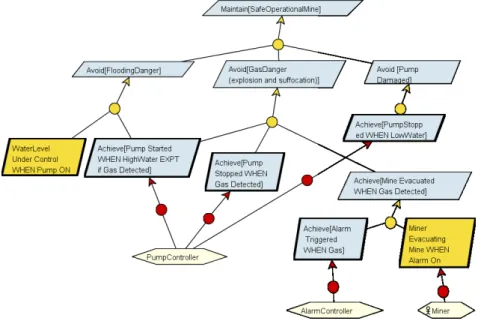
The final model is the agent model showing the flow of information between agents. A flow between two agents requires the sender and receiver to control and
monitor the considered information, respectively. Figure 3 shows the agent model for our mine sump system. Note that a piece of information can only be controlled by a single agent.
Figure 3. Agent Model of the Mine Sump System
It is worth noting that a number of verifications can already be addressed at this level: goal and obstacle refinements, conflicts resolution. Some tool support is avail-able [18], mostly based on model-checking. The Event-B mapping will bridge the gap with the next development step but will also give access to a larger set of tools, including proof-based ones.
3. System Design with Event-B
Event-B is a specification language for developing discrete systems [1]. Behavioural aspects of Event-B models are expressed by means of machines. A machine is defined in terms of a global state consisting of a set of variables, and some events that cause the state to change by updating the values of the variables as defined by the generalised substitution of the event. Events are guarded by a condition, which when satisfied im-plies that the event is permitted to execute by applying its generalised substitution in the current state of the machine. Event-B also incorporates a refinement methodol-ogy, which can be used by software architects to incrementally develop a model of a system starting from the initial most abstract specification and following gradually through layers of detail until the model is close to the implementation. Invariants de-noting desirable behaviour can be specified at each layer of detail as well as across different layers.
In Event-B, an event is defined by a name e, a guard G, expressed as a first-order logical assertion on the state variables, and a substitution S, that updates the values of the state variables. It is syntactically written: ev ::= EVENT e WHEN G THEN S END . 4. Derivation Process
Starting from an operational KAOS specification, the aim of the derivation process is to produce an abstract Event-B model of the system. Our goal is not to produce a
complete and finalised model but rather to produce a sound structure composed of a set of contexts and machines. For this purpose we only consider the semi-formal structure of the requirements model which is always present while the formal level is generally optional and confined to specific critical (part of) systems. Formal re-quirements definition could however also be exploited to drive further refinement as discussed later.
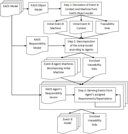
Figure 4. Overview of the transformation
The global process is shown in Figure 4. It is composed of the following steps which are detailed in the rest of this section:
1) starting from the KAOS object model, create an initial Event-B machine and an initial Event-B context to represent the data and general update events.
2) decompose the initial machine using state base decomposition to assign an Event-B machine to each KAOS agent.
3) for each agent machine, derive in a sub-machine refining the agent machine, the events from the requirements/expectations assigned to corresponding KAOS agent.
Throughout the whole process, rich traceability links are generated between the KAOS and Event models. They enable a fine-grained and semantically meaningful control of the impact change in both directions.
4.1. Derivation of Event-B Context and Machine from KAOS Object Model In KAOS, every concept referenced in a goal definition is defined in the object model, which is an Entity-Relationship diagrams [15]. Event-B relies on set theory to define and manipulate data. Transforming an object model into the set-notation of Event-B is like transforming a classical object into relational mapping. It is already addressed by the UML-B plug-in of Rodin [21]. This mapping is summarised in Table 1, for example entities (classes) are mapped to sets, inclusion is used to model specialisation, attributes to injections to name a few.
Table 1. UML-B to Even-B Mapping (taken from [7])
The result applied to our case study is as follows:
CONTEXT MineContext SETS
ONOFF; LEVEL; MINE_SET CONSTANTS
ON; OFF; LOW; MEDIUM; HIGH; M AXIOMS axm1 : partition(ONOFF;{ON};{OFF}) axm2 : partition(LEVEL;{LOW};{MED};{HIGH}) axm3 : partition(MINE\_SET;{M}) END MACHINE MinePump SEES MineContext VARIABLES
MINE; pump; bell; methane; waterLevel INVARIANTS
inv1 : MINE 2 P(MINE_SET) inv2 : pump 2 MINE !ONOFF inv3 : bell 2 MINE !BOOL inv4 : methane 2 MINE !BOOL inv5 : waterLevel 2 MINE !LEVEL
4.2. Decomposition of the Initial Model According to Agents
The main structuring mechanism of Event-B machine which drives the proof pro-cess is refinement. However managing large system requires other structuring mech-anisms to break systems into subsystems. More recently, two decomposition mecha-nisms have been added to Event-B [17]:
–Event-Based decomposition encapsulates the variables in different machines together with the events or parts of events that concern those variables. A variable will thus not appear in more than one machine. The events that have been split will need to be synchronized in order to ensure the functionalities of the original machine. The synchronization will take place by an exchange of inputs and outputs between the synchronized machine’s events.
–State-Based decomposition splits the variables in different machines. A vari-able may thus be present in more than one machine. Such a varivari-able is called shared variables. One of the machines will be the one which effectively updates a shared variable. To keep the other machines synchronised, a special event, called external event, will be added to those other machines
The general idea is to propose an early decomposition to break an initial machine into smaller pieces pertinent with the KAOS agents. The process is to derive separated machines with the attributes monitored and controlled by the agent. TheState-Based decomposition is applied after the creation of the initial machine and context from the KAOS object model with one agent machine per KAOS agent. The reason of this choice is simple, the KAOS meta-model states that an attribute or association cannot be controlled by more than one agent [10, 22]. So it means that in Event-B, a shared variable will be updated in at most one agent machine, while an external event may be placed with each variable coming from the KAOS object model in zero, one or more other agent machines.
The following algorithm gives the different agents machines decomposing an ini-tial machine InitM with an iniini-tial context InitC according to a given KAOS re-sponsibility model:
FOReach KAOS agent ag: Create an agent machine AgM
Declare the InitC context as seen by the AgM machine
FOREACHelement elem of the KAOS object model monitored but not controlled by ag:
Copy the variables of InitM corresponding to this elem in AgM and mark those variables as shared Copy the update event of InitM corresponding to this elem in AgM and mark this event as external FOREACHelement elem of the KAOS object model controlled by ag
Copy the variables of InitM corresponding to this elem in AgM and mark those variables as shared Copy the update event of InitM corresponding to this elem in AgM and mark this event as internal FOREACHinvariant Inv of InitM:
IF Invuses only variables present in AgM,
i.e.variables bound to an element of the KAOS object model controlled or monitored by ag, THENcopy Inv in AgM
fol-lowing:
– a top level MineP ump and its associated MineContext context defining all the required sets. The MineP ump machine is totally unconstrained with respect to the requirements.
– four decomposed machines using state-based decomposition. They show the state variable monitored and controlled by the agent mapped on that machine, the constrained event reflecting the controlled variables such as updateP ump for the P umpControllerand the external events for synchronizing with other machines (re-flecting the monitored variables).
Figure 5. Result of the Decomposition Step
4.3. Implementing Requirements and Expectations Assigned to an Agent
At this point, each agent machine has now a list of shared variables with invariants related to those variables and a list of events representing the evolution in time of those variables. Those events are partitioned into internal events for the variables linked to KAOS elements controlled by the KAOS agent and external events for the KAOS elements monitored by the KAOS agent.
It is now time to cope with the requirements expressed in the KAOS model. Those will be directly formalised into Event-B (as not formalised earlier) and will be
trans-lated into specific model elements following the way they are attached to the require-ments model.
– Maintain requirements will give rise to invariants on the machine under the responsibility of the corresponding agent. This will in turn generate Proof-Obligation on the machine events, i.e. strengthening of some Event guards
– Achieve requirements require more specific modelling to capture progress in-formation (time modelling) and is not directly supported.
Higher-level goals can also be taken into account:
– Maintain goals can translate into system level invariants on the global state ma-chine and trigger a number of proof-obligations through the whole model structure. This is the equivalent of the goal-decomposition proof supported by formal require-ments tools[18].
– Achieve goals can translate into temporal assertions to be model-checked by a tool like ProB [11].
To introduce KAOS requirements for one agent machine, we will first create a refinement of the agent machine. Every requirement and expectation under the re-sponsibility of the KAOS agent may be translated by zero one or more variable, zero one or more invariants and/or zero one or more events in this sub-machine. For in-stance, a requirement saying that the agent has to keep an error rate value under a certain level may be translated as an invariant in Event-B. Another requirement say-ing that the agent has to update a value of the system accordsay-ing to a value comsay-ing from the environment may be translated as an event in Event-B.
If the requirement updates the value of an element elem of the KAOS object model, then the events evts implementing the requirement/expectation will refine the update event declared in the agent machine and associated to elem. So, every event in the sub-machine updating a variable declared in the parent agent machine will refine the update event that modifies the value of this variable in the parent agent machine. We assume here that the KAOS model is consistent and that the refined events are all internal events, meaning that the KAOS element they are coming from is effectively controlled by the KAOS agent linked to the refined agent machine.
// Internal Event derived from requirement
// Achieve[Pump Started WHEN HighWater EXPT if Gas Detected] EVENT high_water_detected REFINES updatePump ANY m WHERE grd1: m in MINE grd2: waterLevel(m) = HIGH grd3: methane(m) = FALSE grd4: pump(m) = OFF THEN act1: pump(m) := ON
For example, the above piece of Event-B presents the implementation of the re-quirements under the responsibility of the P umpController agent. In this refine-ment, the updatePump internal event is refined in a more concrete event called high_water _detectedin order to enforce the requirement Achieve[Pump Started WHEN HighWater EXPT if Gas Detected]. Other requirements are processed simi-larly.
5. Implementation
Both the Objectiver tool for KAOS [19] and the Rodin tool for Event-B [20] have published their meta-model and have also proposed their implementation by using the Eclipse Modelling Framework (EMF). It is possible to use model transformation techniques on the basis of these models to define how the KAOS model translates into the Event-B model.
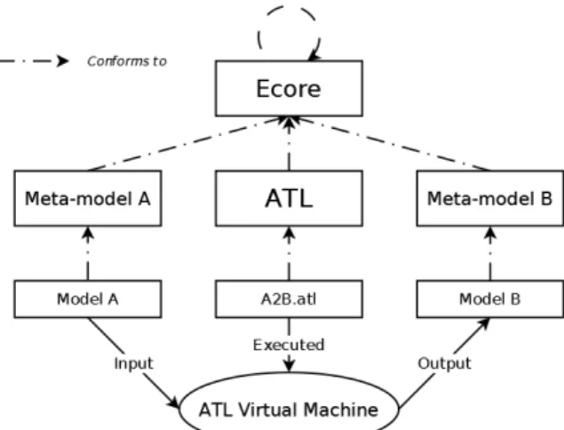
The transformation has been implemented in the ATLAS Transformation Lan-guage (ATL) [6]. It is a model-to-model transformation lanLan-guage based on the OMG’s QVT specification [16]. It uses both declarative and imperative constructs. Declarative constructs are preferred but imperative ones are available to ease complex transforma-tions. An ATL transformation program will therefore correspond to the set of rules defining how source elements are matched to target elements with the initialization of these target elements [9]. The model transformation flow is shown in the Figure 6.
Figure 6. ATL Transformation Flow
The transformation is composed of about 10 rules covering most of the KAOS meta-model. Example of an important transformation rule is described here. It shows how a KAOS agent is mapped onto an Event-B machine based on the algorithm de-scribed in the section 4.2. An important aspect is that traceability links (derivedF romAgent and derivedMachine) are also generated and are available for managing the model
evolution (e.g. enabling impact analysis of changes or possibly an incremental syn-chronisation, in both directions).
-- An agent is translated into a machine -- decomposing the initial machine. rule AgentRule{ from agent : KAOS!Agent to machine : SIMPLEEVENTB!Machine ( id <- agent.name+’_MACHINE’, name <- agent.name,
comment <- ’Create from the KAOS Agent :’+agent.name, variables <- Set{}, invariants <- Set{}, variants <- Set{}, events <- Set{}, refines <- Set{}, refinedBy <- Set{}, views <- Set{}, decomposedIn <- Set{}, recomposedIn <- Set{}, derivedFromAgent <- link, decomposing <- self.initialDecomp), link : SIMPLEEVENTB!AgentDerivation( derivedMachine <- machine, agentId <- agent.id, agentName <- agent.name ) do{ self.project.traces <- self.project.traces.including(link); self.project.elements <- self.project.elements.including(machine); self.initialDecomp.decompMachines <- self.initialDecomp.decompMachines.including(machine); } }
Besides Rodin, the implementation also relies on the UML-B plug-in to manage the data mapping (KAOS object model) and the decomposition plug-in to manage the model structure.
In its actual state, the prototype is limited to the first and second steps of our approach. The initial context, the initial machine and its decomposition in agent machines are automatically derived from a KAOS model. Step three, where agent
machines are refined and requirements/expectations are implemented, has to be done manually.
The prototype available as Eclipse plug-in. Binaries and sources are download-able from http://www.cetic.be/IMG/zip/KAOS2Event-B.zip. It also includes the full ATL model transformation file.
6. Related Work
Other approaches have been designed to address the problem to bridge the gap be-tween RE models and formal specifications. Different groups have explored the con-nection of the pair of languages considered (KAOS with Event-B) either in a generic or more specific context (such as safety or security).
Matoussi describes a process to transform a KAOS goal model into an Event-B specification [14]. This process takes as input a KAOS goal model that is not made operational and produces an Event-B model corresponding to a specification that sat-isfies the requirements described in the input model. This process is based and limited to a few refinement patterns (milestone, case-based...). The idea is that each refine-ment pattern used in the KAOS model will correspond to a refinerefine-ment step in the Event-B model.
To derive an Event-B model from a KAOS model, Aziz propose to include in Event-B the notion of triggered event [2]. This new notion will be used to translate the next (◦) and bounded sooner-or-later (♦≤d) time operators used in the formal
defi-nition of requirements and expectations in KAOS, into Event-B events. The approach is quite formal but does not address our scalability and modularity goals.
Finally De Landtsheer approach is based on the translation of linear temporal logic formula expressed exclusively with past operators into an event-based security policy [4]. The idea was essentially developed for the Polpa policy language but was partially adapted to Event-B.
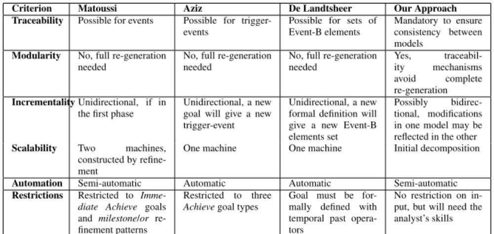
Table 2 compares the above approaches based on the requirements expressed in the introduction of this paper.
Other requirements have also been explored. In [5], Formal Tropos is mapped on business processes. In [3], agents modelling concurrent systems in a distributed environment are transposed into Event-B machines.
7. Discussion and Conclusions
In this paper we proposed a model transformation from requirements models to system design models. The transformation processed by mirroring the agent structure into and Event-B model and also supports the requirements formalisation process. The direct benefits are that quality requirements will results in better, easier to formalise
Criterion Matoussi Aziz De Landtsheer Our Approach Traceability Possible for events Possible for
trigger-events Possible for sets ofEvent-B elements Mandatory to ensureconsistency between models
Modularity No, full re-generation
needed No, full re-generationneeded No, full re-generationneeded Yes,ity mechanisms traceabil-avoid complete re-generation Incrementality Unidirectional, if in
the first phase Unidirectional, a newgoal will give a new trigger-event
Unidirectional, a new formal definition will give a new Event-B elements set
Possibly bidirec-tional, modifications in one model may be reflected in the other Scalability Two machines,
constructed by refine-ment
One machine One machine Initial decomposition Automation Semi-automatic Automatic Automatic Semi-automatic Restrictions Restricted to
Imme-diate Achieve goals and milestone/or re-finement patterns
Restricted to three
Achieve goal types Goal must be for-mally defined with temporal past opera-tors
No restriction on in-put, but will need the analyst’s skills
Table 2. Comparison of different approaches
and prove system models. The strong traceability through the model also allows the analysts to easily identify and correct RE mistakes discovered in the design phase.
Although traceability mechanisms are provided, an important limitation is the ab-sence of direct traceability links between KAOS requirements and Event-B elements. Those are indirect through the relationships bindings requirements with agents and their monitored/controlled information. At this point, we also did not make the choice to formalise requirements because this formalisation is quite an overhead at require-ments level and is partially redundant with the formal Event-B design language. There are also potential semantic issues to address when trying to fully align the respective formal semantics. Some critical properties could however benefit from early formali-sation, especially using linear temporal logic which capture global system behaviour that cannot be specified as such in Event-B, but could be verified using a model-checker like ProB [11]. Our future work will explore this kind of extensions as well as better automation/user interaction support and larger scale validation.
Acknowledgement
This work is funded by the European Commission under the EU project DEPLOY (project reference number 214158). We thanks the anonymous reviewers and Syed Naqvi for their helpful comments.
References
[1] Abrial J.-R., Modeling in Event-B: System and Software Engineering, Cambridge University Press, first edition, June 2010.
[2] Aziz B., Arenas A., Bicarregui J., Ponsard C., Massonet P., “From Goal-Oriented Requirements to Event-B Specifications”, The First NASA Formal Methods Sym-posium (NFM 2009), April 2009.
[3] Ball E., “An Incremental Process for the Development of Multi-agent Systems in Event-B”, PhD thesis, University of Southampton, August 2008.
[4] De Landtsheer R., Ponsard C., Massonet P., “Deriving Event-Based Usage Con-trol Policies from Declarative Security Requirements Models”, Second Int. Work-shop on Security in Model Driven Architecture, Univ. of Pierre et Marie Curie, June 2010.
[5] Decreus K., Poels G., “Mapping semantically enriched Formal Tropos to business process models”, Proceedings of the 2009 ACM symposium on Applied Comput-ing, SAC ’09, New York, NY, USA, 2009, ACM, p. 371–376.
[6] Eclipse, “ATLAS Transformation Language”, http://www.eclipse.org/ m2m/.
[7] Event-B Wiki, “Event-B and Rodin Documentation Wiki”, http://wiki. event-b.org.
[8] Fuxman A., Liu L., Mylopoulos J., Pistore M., Roveri M., Traverso P., “Speci-fying and Analyzing Early Requirements in Tropos”, Requirements Engineering, vol. 9, num. 2, 2004, p. 132–150, Springer-Verlag New York, Inc.
[9] Jouault F., Allilaire F., Bézivin J., Kurtev I., “ATL: A model transformation tool”, Science of Computer Programming, vol. 72, num. 1-2, 2008, p. 31–39, Elsevier. [10] Letier E., “Reasoning about Agents in Goal-Oriented Requirements
Engineer-ing”, PhD thesis, Université Catholique de Louvain, May 2001.
[11] Leuschel M., Butler M., “ProB: An Automated Analysis Toolset for the B Method”, Journal Software Tools for Technology Transfer, vol. 10, num. 2, 2008, p. 185–, Springer-Verlag.
[12] Manna Z., Pnueli A., The Reactive Behavior of Reactive and Concurrent System, Springer-Verlag, 1992.
[13] Matai J., Real-Time Systems: Specification, Verification and Analysis, Prentice Hall International, 1996.
[14] Matoussi A., “Expressing KAOS Goal Models with Event-B”, Proceedings of Formal Methods 2009 Doctoral Symposium, Eindhoven, The Netherlands, Novem-ber 2009, p. 60-67.
[15] OMG, “UML”, http://www.uml.org.
[16] OMG, “Meta Object Facility (MOF) 2.0 Query/View/Transformation Specifica-tion”, July 2007, v 1.0.
[17] Pascal C., Silva R., “Event-B Model Decomposition: A-style vs. B-style”, octo-ber 2009.
[18] Ponsard C., Massonet P., Molderez J. F., Rifaut A., van Lamsweerde A., Van H. T., “Early Verification and Validation of Mission Critical Systems”, Journal of Formal Methods in System Design, vol. 30, num. 3, 2007.
[19] Respect-IT, “Objectiver”, http://www.objectiver.com.
[20] Rodin Open Source Project, “Rodin Event-B toolset”, http:// sourceforge.net/projects/rodin-b-sharp/.
[21] Snook C., Butler M., “UML-B and Event-B: an integration of languages and tools”, The IASTED Int. Conf. on Software Engineering - SE2008, February 2008. [22] van Lamsweerde A., Requirements Engineering: From System Goals to UML
![Figure 1. The Mine Pump System inspired from [13]](https://thumb-eu.123doks.com/thumbv2/123doknet/14569947.727418/3.892.307.578.814.969/figure-pump-inspired.webp)

![Table 1. UML-B to Even-B Mapping (taken from [7])](https://thumb-eu.123doks.com/thumbv2/123doknet/14569947.727418/8.892.220.671.547.777/table-uml-b-to-even-mapping-taken-from.webp)