THE COMPUTING SCIENCE AND TECHNOLOGY INTERNATIONAL JOURNAL, VOL. 2, NO. 1, MARCH, 2012 ISSN (Print) 2162-0660, ISSN (Online) 2162-0687, published online, March, 2012 (http://www.researchpub.org/journal/cstij)
33 h h1 h2 Air a b w Dielectric r Strip
Abstract— Based on a numerical solution of Laplace’s equation
by the finite element method (FEM), we present the electromagnetic (EM) analysis of shielded, suspended and inverted microstrip lines. This technique is adapted to study the complex configuration of the line’s system which does not have a simple analytical solution. The EM parameters are evaluated, and design curves are presented. The obtained results are compared with the available published data and good agreement is found. As an application, the design results of two 20 dB directional couplers are presented using coupled shielded suspended and inverted microstrip lines. Our numerical model remains valid to all configurations of structures that propagate the fundamental TEM mode or quasi-TEM mode.
Index Terms— Analysis and design, EM-parameters, frequency
response, FEM calculations, quasi-TEM lines, shielded inverted microstrip line, shielded suspended microstrip line, S-parameters, 20 dB directional couplers.
I. INTRODUCTION
USPENDED substrate microstrips are very popular transmission media for millimeter and microwave applications. They have low attenuation, small effective dielectric constant, low propagation loss, and low insertion loss. These lines can be of two types, namely suspended and inverted structure. They are known to offer less stringent dimensional tolerances compared with the conventional microstrip lines [1]. These configurations also provide less dispersion than conventional microstrip. The principle reason for their utilization is that these configurations offer lower loss than conventional microstrip [2-3]. The inhomogeneous structures may be used advantageously for the development of filters and couplers as compared to those using homogenous structures [4-5].
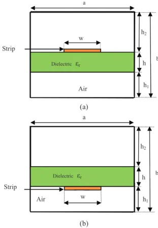
Figures 1 and 2 show respectively the cross section of the shielded suspended microstrip (SSM) and the shielded inverted microstrip (SIM) lines.
Manuscript received on March 9, 2012; accepted on March 15, 2012. Yamina Bekri, Nasreddine Benahmed, Fethi Tarik Bendimerad and Kamila Aliane are with Department of Telecommunications, University Abou Bekr Belkaid-Tlemcen. (e-mail: N_Benahmed@yahoo.fr).
Nadia Benabdallah is with Department of Physics, Preparatory School of Sciences and Technology (EPST-Tlemcen), Tlemcen, Algeria, (e-mail: N_Benabdallah@yahoo.fr.
Various numerical techniques can be used to determine the accurate electromagnetic (EM) parameters of this type of quasi transverse electromagnetic (quasi-TEM) transmission lines [6-13].
In this work, we present both the analysis results obtained by the finite element method (FEM) and the design results of 20 dB directional couplers, using the SSM and SIM lines, operating respectively at 2 and 5 GHz.
(a)
(b)
Fig. 1. Cross-sections of (a) the shielded suspended microstrip (SSM) and (b) the shielded inverted microstrip (SIM), lines.
II. FINITE ELEMENT ANALYSIS
The FEM is a powerful method of analysis suitable for the computation of electric and magnetic fields in strongly inhomogeneous media [14]. Also, it is accurate, efficient and has fast computation speed. In this work it was essentially programmed under freeFEM environment [15] for the characterization of the EM parameters (characteristic