HAL Id: hal-02408701
https://hal.archives-ouvertes.fr/hal-02408701
Submitted on 13 Dec 2019
HAL is a multi-disciplinary open access
archive for the deposit and dissemination of
sci-entific research documents, whether they are
pub-lished or not. The documents may come from
teaching and research institutions in France or
abroad, or from public or private research centers.
L’archive ouverte pluridisciplinaire HAL, est
destinée au dépôt et à la diffusion de documents
scientifiques de niveau recherche, publiés ou non,
émanant des établissements d’enseignement et de
recherche français ou étrangers, des laboratoires
publics ou privés.
Hydraulic logic gates: building a digital water computer
Nicolas Taberlet, Quentin Marsal, Jérémy Ferrand, Nicolas Plihon
To cite this version:
Nicolas Taberlet, Quentin Marsal, Jérémy Ferrand, Nicolas Plihon. Hydraulic logic gates: building
a digital water computer. European Journal of Physics, European Physical Society, 2018, 39 (2),
pp.025801. �10.1088/1361-6404/aa97fc�. �hal-02408701�
Nicolas Taberlet,1,a) Quentin Marsal,1J´er´emy Ferrand,1 and Nicolas Plihon1
Univ Lyon, Ens de Lyon, Univ Claude Bernard, CNRS, Laboratoire de Physique, D´epartement de Physique, F-69342 Lyon, France
(Dated: 13 December 2019)
In this article, we propose an easy-to-build hydraulic machine which serves as a digital binary computer. We first explain how an elementary adder can be built from test tubes and pipes (a cup filled with water representing a 1, and empty cup a 0). Using a siphon and a slow drain, the proposed setup combines AND and XOR logical gates in a single device which can add two binary digits. We then show how these elementary units can be combined to construct a full 4-bit adder. The sequencing of the computation is discussed and a water clock can be incorporated so that the machine can run without any exterior intervention.
I. INTRODUCTION
Physics has been the cornerstone of all major technical advances throughout the history of computing1, with
fundamental concepts emerging from solid and fluid mechanics, electronics and solid-state physics, as well as quantum physics in recent years. In mechanics, pin-wheel computers include Pascal’s calculator2
(de-signed as early as 1642, the Pascaline was the first calculator to be patented), the arithmometer (the first mass-marketed commercial calculator, about 5500 units were produced and sold world-wide)3, Babbage’s programmable analytical engine (designed in 1834 and considered to be the ancestor of modern computers4) or
the famous cypher enigma machine, most notably used by Nazi Germany during WWII5. In fluid mechanics,
processing and computing devices include the Tesla valve6,7, pressure-actuated valves acting as analog transistors, non-linear amplifiers relying on deflecting a weaker jet striking a stronger jet of fluid8, digital
pneumatic logic gates9,10, as well as the MONIAC
(a water-based analog computer designed to model economy).11,12 It is important to note that computing using advanced fluidics systems was deeply studied and implemented in operational systems until the 1970’s13? , before fluidics could not compete against
electronics. In electronics, vacuum tubes14 remained
fundamental components for electronics throughout the first half of the XXth century15 until the invention of semiconductors and the discovery of the transistor effect (which was honored with the Nobel Prize in Physics in 1956)16. Another leap came with the invention of the
integrated circuit (patented in 1959) for which Kilby won the 2000 Nobel Prize in Physics16. Finally, the concept of quantum computation has attracted much interest in the past two decades17–19. While promising
recent technical developments in this field brought the concept closer to reality20,21, building a fully-functioning
large-scale quantum computer still remains a challenge.22
a)Electronic mail:[email protected]
One of the most fundamental tasks any computer has to perform is arithmetic operations. Adding binary num-bers (a and b) is nothing more than the routine children are taught in elementary school. For example, 1101 + 1001 (i.e. 13+9) is computed as follows (starting from the right-most digit):
• 1 and 1 is zero and 1 is carried
• 0 and 1 is zero, which makes 1 with the carry • 1 and 0 is one,
• 1 and 1 is zero and 1 is carried • resulting in 10110 (=22).
In this paper we present an easy-to-built hydraulic dig-ital adding machine with relies on simple physical prin-ciples proposed by Gitton23. We first explain (section
II) how using a siphon, a slow drain and a overflowing
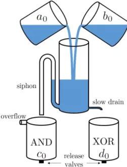
FIG. 1. Hydraulic digital arithmetic unit: the content of one (and only one) cup (i.e. 1+0) slowly leaks out of the central container through the XOR gate while the content of two cups (1+1) primes the siphon and is rapidly evacuated through the AND gate. The smaller cups have a volume of 25 mL while that of the central container is 50 mL, and the height of the siphon is 2/3 of the total height.
2
gauge one is able to construct AND and XOR logic gates in one single device. In section III we explain how these processing units can be arranged so as to form a full binary adding machine, while section IV describes the experimental 4-bit water computer that we have built.
II. ADDING TWO DIGITS
Logical operations
Adding the first digit of each number (a0 and b0) yields
the first digit of their sum (d0) and the first carry (c0).
The carry is 1 if and only if a0 = b0 = 1 while the first
digit of the sum is 1 if and only if either a0 or b0 is 1
(not both) (see Table I). In terms of logical operations this can be summarized as:
( c0= a0 AND b0 d0= a0 XOR c0 (1) a0 0 0 1 1 b0 0 1 0 1 c0 0 0 0 1 d0 0 1 1 0
TABLE I. Carry, c0, and digit, d0, of the sum of a0 and b0.
In logical operations: c0= a0AND b0 while d0= a0 XOR b0.
Hydraulic AND and XOR gates
The addition of the first two digits therefore only requires an AND and XOR gate. The hydraulic device shown in Fig. 1 combines both gates in one single apparatus. It consists in a central container into which the content of two smaller cups (representing a0 and b0) is
simultane-ously poured. The cups can be either completely empty (representing a 0) or completely full (representing a 1) and their volume is half that of the central container. A small hole is drilled at the bottom of the main container (bottom right in Fig. 1) so that its content can slowly drain out. On the other side (bottom left in Fig. 1), a large hole is connected to a siphon, whose height is greater than half of that of the main container.
If one and only one of the top cups is full, the water poured into the central container gradually winds up in the bottom-right cup. On the other hand, if both top cups are full, the siphon is almost instantly primed and the content of the main container quickly empties out into the bottom left cup, whose overflow tube ensures that the results remains binary. Overflow is a generic feature of fluidics devices in which vents were widely im-plemented24. Note that even when the siphon is primed
and the water is quickly evacuated, a small amount still leaks through the slow drain. The diameters of the drain and siphon must be chosen so that the flow rate through the siphon is far greater.
Therefore, the bottom cups give the results of the logical operation AND (for the left cup) and XOR (for
the right cup). The smaller cups (top and bottom) act as memory units while the larger central container incorporates the logic gates.
It is important to note that the gates presented here are basic digital components which do not rely on basic analog hydraulic components. This is a fundamental dif-ference with electronic digital circuits, designed as the as-sociation of several analog circuits, namely transistors25.
Technical details
The central container is a 50 mL plastic test tube, 27 mm in diameter. The smaller cups (memory units) are made of the same test tube cut in half (25 mL). The hole through which water slowly drains out is pierced using an incandescent needle which gives a diameter of typi-cally 500 µm (±20%). The siphon and the overflow tube are built using plastic straws (5mm in diameter). Straws are very convenient as they are made to be bent without buckling or pinching. In this device it took approxima-tively 2 min for the content of one cup (25mL) to slowly drain through the XOR gate whereas it takes less than 5 s for the content of two cups (50mL) to quickly evacuate through the AND gate (the primed siphon).
In order to guide the water gradually leaking through the XOR gate, a straw (see Fig. 3) is glued around the small hole. A release valve, consisting in a 5 mm rubber stopper, is placed at the bottom of each memory unit for further processing.
Note that capillary effects may cause a number of prob-lems: some liquid can stay trapped in the straws while the flow through the small drain can be hindered. This can be overcome by reducing the surface tension of the liquid. Soap must be avoided since it creates bubbles or foam but adding a small amount of ethanol to the water is enough to considerably help.
III. FULL-ADDER
Adding the nth digits
The device sketched in Fig. 1 allows one to add two 1-bit numbers and yields a 2-bit number and is known as a half-adder.26 As explained above, it can be used to compute the sum of the first digits (a0and b0). However,
when adding any nthdigits (a
nand bn), the carry (cn−1)
originating from all previous calculations must be taken into account. A full-adder is therefore an operation with three inputs and two outputs : (an, bn, cn−1) → (cn, dn).
As illustrated in the introductory addition of 1101 (13) and 1001 (9), a full-adder must first add the nth
digits together, their XOR result then needing to be added to the n − 1th carry. That second operation gives
the nthdigit of the sum (d
n). The AND results of both
computations give the nthcarry. Note that not possible
for both AND gates to yield 1 and no further precaution (such as an additional OR gate) needs to be taken. The combination of two half-adders is known as a full-adder and a sketch of a device built with our hydraulic gates
is shown in Fig. 2.
Clock rate
When using a full-adder, great care must be given to the timing of the operations. The first half-adder (container 1 in Fig. 2) can perform its computation as soon as the device is started (t=0) but the second computation (con-tainer 2 in Fig. 2) must wait for all previous operations to have been performed. As explained above, the output of a AND gate in our device is given in less than 5 s while that of the XOR gate is given in T = 2 min. Therefore, one must ensure that enough time is given for all half-additions to be over before further processing. Therefore, the second operation of the nth full adder must be per-formed at time t = nT . Our water computer can only boast a disheartening clock rate of the order of 0.01Hz, far less than the typical 1010Hz of modern microchips.27
For the sake of simplicity, the version of the full adder presented here does not include a fully integrated hy-draulic clock and relies on the successive manual opening of valves. However, it is in principle possible to build a dedicated clock which uses hydraulically controlled valves and whose sequencing is governed by the associated tim-ing diagrams of the computer24.
FIG. 2. Sketch of a full-adder allowing one to add two digits (an and bn) while taking into account the carry (cn−1)
re-sulting from the earlier stages of computation. The full-adder yields the nth digit of the sum (dn) as well a the nth carry
(cn). The computation must be sequenced so as to ensure
that the second computation of the stage (2) is triggered only after all previous operations have terminated.
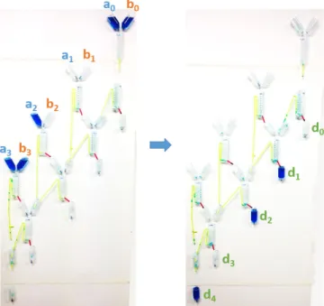
FIG. 3. Pictures of our 4-bit hydraulic digital adder made of 7 processing units. The initial state shows the two numbers to be added (a = 1101) and (b = 1001) and the result can be read in the final state (d = 10110) after 8 minutes of computation.
IV. 4-BIT HYDRAULIC DIGITAL COMPUTER
A full 4-bit adder
Figure 3 shows a 4-bit adding machine built by as-sembling 7 half-adders. As explained in section II, the memory units (the smaller cups) are emptied out into the processing units (the central containers) through 5-mm holes at their bottom when rubber stoppers are removed. The red straws channel the results of the XOR gates into the memory units while the AND gates (the siphons) are made of green straws. For clarity, the water is died blue. The initial state is shown on Fig. 3a: a = 1101 (= 13) and b = 1001 (= 9). After 8 minutes, the computation is complete and the result can be read in the bottom memory units (Fig. 3b). As expected the sum is indeed d = 10110 (= 22).
Subtraction
The digital hydraulic adder presented above can also be used to perform subtractions (13-9 for instance) using a method known as the two’s complement28, that allows one to use signed binary numbers. The two’s complement defines negative 9 as -9 = NOT(9)+1, to which 13 can be added. Table II presents the operation. The result must not be interpreted as a 5-digit number since obviously the difference between two 4-digit numbers is less than 15. Instead, the 5th is only an indication of the sign. In the example shown in Table II, the result, 1 0100, must be read as +4.
The NOT operation can be performed using the hy-draulic half-adder presented in section II since for each
4 9 1 0 0 1 NOT(9) 0 1 1 0 NOT(9)+1 0 1 1 1 +13 1 1 0 1 -9+13 1 0 1 0 0
TABLE II. Computation of 13-9 using the two’s complement method in which -9 is given by NOT(9)+1. Since the differ-ence cannot exceed 24− 1 = 15, the 5thdigit must be ignored,
and the result is 0100=4, as expected.
digit NOT(an)=an XOR 1. One simply needs to collect
the result of the XOR gate (the slow drain), the b cup being always filled, while the result of the AND gate is irrelevant. The 4-bit adder presented in section IV can then first be used to add 1 to -9, and then used again to add 13 to the result.
V. CONCLUSION
In this paper, the principle of a digital binary adder was described and the use of the AND and XOR logic gates was explained. We proposed a simple arithmetic unit relying on hydraulic principles which combines both AND and XOR gates in a single device, easily built with plastic test tubes and straws. Arranging 7 of these ele-mentary processing units, a functioning hydraulic 4-bit digital adder was constructed. The proposed design can be improved in several ways.
A water-based clocked can be built to automatically trigger the computation every two minutes. Weights at-tached to the two rubber stoppers above the processing unit, through initially loose strings, can be placed on a balance beam with a leaking cup of water acting as a counterweight. After the desired duration, the balance beam tips over, causing the weight to fall and to pull the stoppers out, thereby releasing the water, i.e. triggering the computation. Such a simple independent clock allows the machine to run free of any human intervention during the computing process (which viewers may perceive as a deception).
Moreover, it is well known that during the adding pro-cess information is lost (in mathematical terms, addition is not bijective). Obviously, for instance adding 13 and 9 yields the same results as adding 8 and 14. However, in our 4-bit adding machine, a trick might be used to iden-tify the original numbers (a and b) from the result (d). If each initial digit is assigned a specific color, then ana-lyzing the hue of the final digits in the sum could allow one to deduce the value of the two initial numbers.
ACKNOWLEDGMENTS
The authors acknowledge support from the University Lyon Claude Bernard, the Soci´et´e Fran¸caise de Physique
and from the ´Ecole Normale Sup´erieure de Lyon and its Physics Department and Laboratoire de Physique.
1M. Wolf, The Physics of Computing. Elsevier, 2016.
2D. Adamson, Blaise Pascal: mathematician, physicist and
thinker about God. Springer, 1994.
3E. D. Reilly, Milestones in computer science and information
technology. Greenwood Publishing Group, 2003.
4B. V. Bowden, “Faster than thought: a symposium on digital
computing machines,” 1953.
5W. Kozaczuk, Enigma: how the German machine cipher was
broken, and how it was read by the Allies in World War Two. Foreign intelligence book series, University Publications of Amer-ica, 1984.
6P. Tabeling, Introduction to microfluidics. Oxford University
Press on Demand, 2005.
7D. E. Angelescu, Highly integrated microfluidics design. Artech
House, 2011.
8T. M. Hunt, T. Hunt, N. Vaughan, and N. Vaughan, The
hy-draulic handbook. Elsevier, 1996.
9M. Rhee and M. A. Burns, “Microfluidic pneumatic logic circuits
and digital pneumatic microprocessors for integrated microfluidic systems,” Lab on a Chip, vol. 9, no. 21, pp. 3131–3143, 2009.
10R. Dewhirst, Passive Pneumatic Half-adder with No Moving
Parts. Massachusetts Institute of Technology, Department of Mechanical Engineering, 1964.
11C. Bissell, “Historical perspectives-the moniac a
hydromechan-ical analog computer of the 1950s,” IEEE Control Systems, vol. 27, no. 1, pp. 69–74, 2007.
12D. Colander, “The moniac, modeling, and macroeconomics,”
Economia politica, vol. 28, no. 1, pp. 63–82, 2011.
13J. Kirshner, Design theory of fluidic components. Academic
Press, New York, 1975.
14H. Schultz and W. Wadey, “A laboratory course in electronics,”
American Journal of Physics, vol. 19, no. 4, pp. 214–223, 1951.
15S. Macdonald and E. Braun, “The transistor and attitude to
change,” American Journal of Physics, vol. 45, no. 11, pp. 1061– 1065, 1977.
16N. Weste, D. Harris, and A. Banerjee, “Cmos vlsi design,” A
circuits and systems perspective, vol. 11, p. 739, 2005.
17C. H. Bennett and D. P. DiVincenzo, “Quantum information and
computation,” Nature, vol. 404, no. 6775, pp. 247–255, 2000.
18N. D. Mermin, “From cbits to qbits: Teaching computer
scien-tists quantum mechanics,” American Journal of Physics, vol. 71, no. 1, pp. 23–30, 2003.
19D. Candela, “Undergraduate computational physics projects on
quantum computing,” American Journal of Physics, vol. 83, no. 8, pp. 688–702, 2015.
20L. DiCarlo, J. Chow, J. Gambetta, L. S. Bishop, B. Johnson,
D. Schuster, J. Majer, A. Blais, L. Frunzio, S. Girvin, et al., “Demonstration of two-qubit algorithms with a superconducting quantum processor,” Nature, vol. 460, no. 7252, pp. 240–244, 2009.
21N. Somaschi, V. Giesz, L. De Santis, J. Loredo, M. P. Almeida,
G. Hornecker, S. L. Portalupi, T. Grange, C. Ant´on, J. Demory, et al., “Near-optimal single-photon sources in the solid state,” Nature Photonics, 2016.
22C. P. Williams, Explorations in quantum computing. Springer
Science & Business Media, 2010.
23“B. gitton.” https://en.wikipedia.org/wiki/Bernard_Gitton.
Unfortunatly Gitton’s design seems to have remained unpub-lished but a device using his concept was built at the Technisches Museum of Vienna, Austria.
24C. A. Belsterling, Fluidic systems design. Wiley Interscience,
New York, 1971.
25P. Horowitz and W. Hill, The art of electronics. Cambridge
Univeristy Press, 1989.
26D. Page, A practical introduction to computer architecture.
27M. J. Rodwell, High-speed integrated circuit technology: towards
100 GHz logic, vol. 21. World Scientific, 2001.
28L. Null, J. Lobur, et al., The essentials of computer organization