HAL Id: hal-01386507
https://hal.inria.fr/hal-01386507
Submitted on 24 Oct 2016
HAL is a multi-disciplinary open access
archive for the deposit and dissemination of
sci-entific research documents, whether they are
pub-lished or not. The documents may come from
teaching and research institutions in France or
abroad, or from public or private research centers.
L’archive ouverte pluridisciplinaire HAL, est
destinée au dépôt et à la diffusion de documents
scientifiques de niveau recherche, publiés ou non,
émanant des établissements d’enseignement et de
recherche français ou étrangers, des laboratoires
publics ou privés.
Distributed under a Creative Commons Attribution| 4.0 International License
Unification of Multiple Models for Complex System
Development
Nesrine Ben Beldi, Lionel Roucoules, François Malburet, Tomasz Krysinski,
Pierre Gauthier
To cite this version:
Nesrine Ben Beldi, Lionel Roucoules, François Malburet, Tomasz Krysinski, Pierre Gauthier.
Unifi-cation of Multiple Models for Complex System Development. 11th IFIP International Conference on
Product Lifecycle Management (PLM), Jul 2014, Yokohama, Japan. pp.267-276,
�10.1007/978-3-662-45937-9_27�. �hal-01386507�
Unification of multiple models for complex
system development
Nesrine BEN BELDI (1, 2), Lionel ROUCOULES (1), François MALBURET (1), Tomasz KRYSINSKI (2), Pierre GAUTHIER (2)
Arts et Métiers ParisT ech, CNRS, LSIS, 2 cours des Arts et Métiers, 13617 Aix en Provence,France
PSA Peugeot Citroen, Innovation powertrain project, 18 rue des fauvelles 92250 La Garenne Colombes, France
[email protected] / [email protected]
Abstract: In the design of automotive product, the constant evolution of customer
requirements and international regulations leads to new considerations of the sys-tem design process. The authors propose a modeling approach for complex s yssys-tem design based on the coupling of collaborative models and heterogeneous experts’ (i.e. authoring) models used for product behavior assessment. The approach aims at modeling a system at different systemic and temporal levels in the design pro-cess and allows a flexible navigation with the possibility of changing or adding models in the design space. The purpose behind the use of this approach is to lead to an optimal design solution in the context of innovative design for complex sy s-tem.
Keywords: Mechanical system design, Model Driven Architecture (MDA),
de-sign system process, data modelling
1
Introduction
Automotive industry market is witnessing a continuous expansion which is chang-ing from a local to a global one. Nowadays, car manufacturers are findchang-ing them-selves forced to assure the requirements of an international market that needs to be satisfied, taking into account new regulations in terms of cars’ pollutant emissions. This expansion has led automotive designer to innovate and make an evolution in their designed products. Consequently, in order to realize that, they have to con-sider their product design process in another way in order to take into account the-se new design requirements and constraints.
Concepts of design process and complex system modeling are presented in the se-cond section of the communication. A particular focus towards their applications
in the automotive field is given in order to set forth the design methods applied and modeling tools used.
The third section, introduces the different models for system design found in the scientific literature. Our focus is done towards the interaction of all those mo dels used in a design process and how they are linked together. The issue of design d a-ta transfer between one model to another according to the level of the granular de-composition of the system is discussed highlighting the interoperability between models in complex system modeling for design purpose.
Section fourth proposes the unification models approach based on a mediator structure. Such approach allows a dynamic navigation in the design environment between expert’s (i.e. authoring) models at different granular levels of the system decomposition. Design constraints are taking into account from the beginning of the modeling and evolve simultaneously by the evolution of the model itself. The proposed Information Technology (IT) system is also presented and discussed with respect to interoperable performances.
The fifth section, illustrates this proposal by presenting its application on a me-chanical system. The aim is to evaluate the pertinence of the modeling approach proposed in order to optimize the design of complex system in a context of inn o-vative design.
Conclusion and recommendations for further work are therefore presented.
2
Complex system design process and modeling
Automotive products are considered as complex systems, since their design re-quires an effort of understanding relationships among knowledge [1] of several scientific domains: mechanics, hydraulics, electronics and automatics, mathemat-ics, Information Technologies, etc. The multi-physic aspect for such systems im-plies the involvement of multiple experts according to the knowledge required. In-deed, each experts has its own representation (i.e. model) of the system; each model being different than the others. Each model is therefore created for a specif-ic use and product assessment (functional analysis, CAD, CAE, CAM, etc.). As presented in [2], in a groovy design approach where system specifications are known through previous experimentations, design activities are considered as a simultaneous and/or sequential concatenation of expert knowledge to find “best” values of an already-defined-product breakdown and already identified product parameters. On the other hand, innovative design approach involves new knowledge considering the system configuration since the design activity is to find new solutions (i.e. alternatives) in the design solution space. The innovative alter-natives can be found either in the functional, conceptual, embodiment or detail de-sign phases of the whole dede-sign process [3].
During the design process, the impact of each expert is therefore considered as a constant loop leading to the augmentation of the amount of product data dealt with (scientific knowledge, design constraints, system specifications, models data,
3
physical principle, etc.) [4]. Such expert’s specification depicts a function in the design process and is translated according to the concept of
Knowledge-Intensive-Engineering [5] by technological attributes. In this amount of design alternatives,
the final decision making is done according to performances assessments. Never-theless, this assessment has to take into account both local and global system per-formances based on multiple-perspective criteria.
One of the greatest challenges in this context related to complex system de-sign is therefore to get to a complete mastery of the evaluation and the control of the relationships existing between all of the defined product’s models tak-ing into account their various specifications.
3
Overview of the state of the arts with respect to Product
Meta-Models used in innovative complex system design
3.1 Product Meta-models over the whole product life cycle
According to [6], building a model is an iterative procedure. It starts with the iden-tification of essential features of inherent mechanisms of a dynamic sy stem to be designed. In a step by step refinement of the understanding of a dynamic phys ical system, different forms of representation are used.
When processing a design problem, according to Pahl & Beitz’s phases, four ma-jor aspects have to be taken into consideration for the system definition: The sy s-tem functional description, the concepts selection, the embodiment of the syss-tem architecture (i.e. product breakdown) and the detailed parameters definition.
Functional description of a system can be done through models such as
“Func-tional Block Diagram” [7] or “FAST Diagram” [8], etc. Those models are made in order to define the functional behavior of the system in terms of required perfor-mance. That enables the determination of first possible configurations for the technical solution that represent the system concept selection. These models are complementary to systems engineering activities and they represent the first level of system modeling leading to fix its operational concept [9].
In order to evaluate the energetic aspect of a system, representation models can al-so be used, and their exploration leads often to the establishment of the system control system strategy. Bond Graph models falls precisely within this context. This language of modeling consists in representing the energetic flows transfer be-tween system components and sub components, bringing up the relations of cause and effect existing between each part of the system in order to systematically co n-struct the mathematical models that will be used for system control.
Finally, current design practices use a lot of models in the detailed design phase to model form features (ex. CAD model) and assess the numerous multi-physics
product’s behaviors (ex. Finite Element Analysis models). A lot of authoring
ap-plications currently exist in commercial or academics solutions.
3.2 Meta-Models for collaborative relationships definition,
information classification and retrieval
The previous section has presented meta-models related to specific design phase. Those meta-models are generally defined by specific individual designer.
Another level of meta-model is also used to define relationships among all those design phase (function, concepts, detailed design) and product assessment (man u-facturing, structural analysis…) and to classify all the information (i.e. knowledge) in order to be retrieved (i.e. knowledge management) . The scientific literature gives plenty of Meta-Model proposals that all treat those two levels of concepts (knowledge modelling and knowledge relationships): Core Product Model [10] (CPM), FBS [11], MOKA model [12], PPO model [13], KC model [14].
3.3 Discussion on the state of the arts towards the scientific and IT
proposal
Since many meta-models have been proposed in commercial or scientific solu-tions, it appears idealist for us to find only one (i.e. integrated model) that could be the “best” one and that could gather all the conceptual fundaments. Many stand-ards have also been proposed for many years but none has been accepted as uni-versal so far (cf. STEP, SYML, PLCS… [15]).
Therefore, authors argue that the current issue is then not to battle about which model fit the best anymore. It would be a wrong approach. As discussed in [16], authors argue that it is better to go toward a flexible approach that should be a h y-brid one based on federative and unified approach (cf. figure 1): federative ap-proach goals at linking straight one meta-model to another one (concepts of A are linked to concepts of B), unified approach goals at linking one meta-model to oth-ers via a mediator. A mediator can be one of the meta-model presented in 3.2. In a recursive mode, one mediator can be federated to another one. That approach goes toward a more adaptive way of modeling since concepts (seen as a meta-model) can be added or removed over the time and depending on the industrial design context. The “best model structure” is therefore the one set according to each
de-5
sign situation. This paper is focused on “unified meta-modeling”. Federative ap-proach can be found in [16].
Expert Meta-Model 1 Mediator meta-model 1 Mediator meta-model n Expert Meta-Model 2 Federation link Unification link Expert Meta-Model n
Fig. 1.Hybrid Federative and Unified approach
In the following section, authors propose a modeling approach based on the con-cept of Model Driven Engineering [17] which allows a flexible navigation with the possibility of changing or add models in the design space. This approach a l-lows the coupling of unified collaborative meta-models and heterogeneous ex-perts’ (i.e. authoring) meta-models used for system behavior assessment.
4
Proposal: Model Driven Engineering approach for complex
system modeling
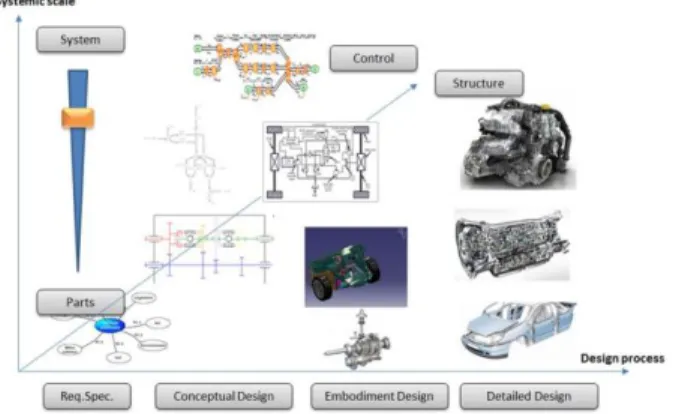
As previously introduced, numerous models have to be set during the design phase. To treat the design of complex systems authors use a classification based on three main axes (cf. figure 2):
Product life cycle mainly restricted of design phases as defined in [3]
System granularity as mentioned in system engineering concepts
Structure/Control chain axis of the dynamic system in order to link Multiple-perspective modeling in both structural and control domains.
4.1 Mediator meta-model for unification approach
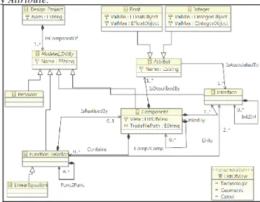
While modeling a complex system, multiple views representing the evolutio n of the system and its components during the design process can appear depending on the complexity of the system itself and the number of performance required. Those views go from a macroscopic representation of a general functional view of the system to a specific technological or geometrical view of a sub component of it. In order to represent that aspect while modeling a complex system, experts use multiple-view models to separate concerns during the design process and to co n-trol system evolution at different levels from functional aspects to deployment and verification. The concepts of this modeling are issued from works done by [13] in order to optimize the gathering of system information and formalization of the e x-isting relations between it. These concepts have been updated and are given in fig-ure 3:
Component that represents the used objects to describe the system. This
de-scription can be done at different granular and multiple-views levels.
Interface defines the part of one component allowing it to be in a relation with
another one.
Relations in order to formalize the existing relations between components
through Interface.
Each of the above concepts is inherited from the virtual classes Modeled Entity in order to construct the global mediator model. Each Modeled Entity is de-fined by Attribute.
Fig. 3.Current mediator meta-model
In a context of innovative design, mastering the complete evolution of a complex system as for its components and sub components, is a work that is build and done through the evolution of the design process itself. Experts’ models are constructed
7
upon specific design constraints in order to validate a specific performance at each level of the system decomposition. And they evolve in a dynamic way during the design process. Thereby, experts can be brought to add and/or suppress some models or design constraints at some level during the design process.
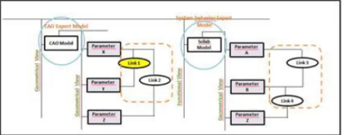
The author proposes to work on a certain level of system modeling in order to cre-ate flexible and dynamic information exchange between design experts during a design process. This can be done through a representation of the existing math e-matical and/or physical relations between the parameters of each expert’s model at different systemic level of the system, insured through a constraint propagator. The concept of multiple views that is used in this approach represents the different part of the product breakdown and the set of parameters that are shared among ex-perts. That is the main role of a mediator model. (cf. figure 4).
Fig. 4.Multi-views Decomposition of the system based on mediator model given on Figure 3
Expert models can be found at different levels in system decomposition. A part from views related to the global system; components, sub components and sub -sub components can have also views related to the expertise used for their design and their own performance to validate (manufacturing, multi-physics simulation, CAD…). And by that, expert models can be found at different systemic level and can have a local use (validate a component performance) and/or a global use (val-idate a component function and its interaction with other components) (cf. fig-ure 4). Thus, authors show that it is possible to create a flexible navigation process between each model and another based on the modeling of the existing relations between the specific parameters of each models and by that the design constraints used to build each model and design the system. Relations manage both break-down relationships (i.e. system engineering relations) and parameters relationships to be used in a local or global constraints solving problem to insure coherency among designers’ knowledge. For instance, during the design of a mechanical sys-tem the CAD expert can decides to review a technical constraint that he has con-sidered at the beginning of modeling and that is no more suitable at this stage of system design (cf. figure 4, Link1). This reconsideration automatically leads him to readjust the value that he has chosen before for the different parameters in order to integrate this constraint and also to make sure that the other constraints of his model are still respected. But by doing that, he is also changing the common p a-rameter (paa-rameter Z) that exists between his CAD model and the Scilab model of the system behavior expert. This parameter is going to influence the results given
by the Scilab model through its relations with other parameters specific to Scilab model (parameter A, B), and of course the constraints considered by the system behavior expert while building hid functional model to validate his desired per-formance. This change is transferred to the system behavior expert by a notifica-tion alert appearing in the funcnotifica-tional model. This transfer is ensured through the mediator meta-model that contains all the relations between the existing parame-ters that are common in both models.
4.2 Infrastructure of the information system
As far as Information technologies are concerned, and in coherency with modeling approaches presented in the previous section, authors argue that one unique inte-grated software solution is an idealist solution. Industrial and modeling context are indeed evolving very often over the time. IT system has therefore to be flexible (i.e. agile). The infrastructure that has been developed is therefore based on many layers (cf. figure 5) implemented into the Eclipse Modelling Framework (EMF):
Authoring applications (i.e. expert model) used by design experts.
Unification layer that manage the relationships. This layer allows the navig a-tion among the entire three axes space of data (cf. figure 2).
External CSP solution that keeps the coherency among relationships .
Expert model 1
(native format)
Mediator meta-model (*.xmi)
(for information classification and relationships modelling)
X models to Mediator projection mechanisms (injection and extraction)
Collaborative space CSP
external application
Expert model 2
(native format) Individual space
Fig. 5.Layers of the developed IT infrastructure implemented in EMF
As far as the design context is defined, adequate authoring ap plication can be plugged or unplugged to the unification layer. This plug function is based on M e-ta-model projection [16] that allows easy way to use the “best” application for the current situation.
5
Illustration of the approach through the modeling of
mechanical coupling system for hybrid transmission
In order to validate the modeling approach, a case study of hybrid transmission system is considered in the context of innovative powertrain project (cf. figure 6).
9
The geometrical view is done through CAD modeling tools and the functional view is achieved through Scilab tool. Each one of the models is built by an expert in order to select the “best” architecture for the system allowing validating the fixed performance that is CO2 emission for a driving cycle.
Fig. 6.Multi views modeling for hybrid system
The multi view model is constructed in parallel to the design of the system allo w-ing masterw-ing at different levels the relations between the different parameters. And from that base, the mediator model is constructed taking into account these relations and a navigation between one model to another and one view to another (i.e. navigation between geometrical view and functional scilab view). This model integrate the possible changes, adds and retrieves that can occur on the different parameter of each model and allow the propagation of its related information to other models.
6
Conclusion and recommendations for further work
In order to support the design of complex system in innovative design context, the authors propose to model and optimize the design process through a unification approach by allowing the navigation product models based on a three axes design framework. This navigation can be done through a model driven architecture concept based on a mediator meta-model that takes into account the existing relations between product breakdown and parameters of each model. This provides a new approach in order to support data exchange and to accelerate time consuming tasks. This approach is more flexible s ince it is based on one meta-models and agile IT solution that can be modified or changed according to the modifications occurring on experts ’ models and design environment.
The illustration of this approach is done through a hybrid powertrain system for its prototype design. The implementation of this proposal in EMF (Eclipse Modelling Framework) is in progress. A possible further work will be to test the approach for the design of the series version of the hybrid powertrain system and to define performance indicators allowing optimizing the process design and the system architecture.
References
1. Suh N.P. (1999), Applications of Axiomatic Design, Integration of process Knowledge into Design Support, ISBN 0-7923-5655-1, Kluwer Academic Pub-lishers.
2. Frey E., Gomes S., Yan X.T. (2010), Numeric chaining of design process In-formation for mechatronic products, Mechatronics conference, Zurich.
3. Pahl G., Beitz W. (1996), “Engineering Design: A Systematic Approach”, vol. 2nd edition, London, springer verlag_edition.
4. Roucoules L., Lafon P., et al. (2006), Knowledge intensive approach towards multiple product modelling and geometry, CIRP Design Seminar, Alberta (Ca). 5. Tomiyama T. (1995), A design process model that unifies general design theory
and empirical findings, Design Engineering Technical Conferences – ASME 95, Boston, USA.
6. Borutzky W. (2010), Bond Graph Methodology: Development and analysis of multidisciplinary dynamic system models, London, springer verlag_edition. 7. AFNOR (1988) Recommandation pour obtenir et assurer la qualité en
concep-tion, norme X50-127.
8. Bytheway C. (2007), FAST Creativity & Innovation, ed. J.Ross Publishing, ISBN1-932159-66-5.
9. Luzeaux D., Ruault J.R., (2013) l’Ingénierie système, AFNOR edition. 10.Sudarsan, R., S.J. Fenves, R.D. Sriram, and F. Wang. (2005), A product
infor-mation modelling framework for product lifecycle management, Computer-Aided Design 37 (2005): 1399-1411.
11.Gero J.S. (1990), Design prototypes: a knowledge representation schema for design, AI Magazine Vol. 11 No 4 pp 26e36.
12.Stokes, M. (2001), Managing engineering knowledge: MOKA methodology for knowledge based engineering applications, MOKA Consortium, 2001.
13. Noël F., Roucoules L. (2007), The PPO design model with respect to digital enterprise technologies among product life cycle, in International Journal of Computer Integrated Manufacturing, DOI: 10.1080/09511920701607782, 21 (2) , pp. 139-145.
14. Badin, J. (2011), Using the Knowledge Configuration Model (KCModel) to manage configurated knowledge for upstream phases of the design Process, Ed-itorial Manager(tm) for International Journal on Interactive Design and Man u-facturing (IJIDeM).
15. Rachuri, S., Subrahmanian, E., Bouras, A., Fenves, S., Foufou, S., and Sriram, R. (2008), Information sharing and exchange in the context of product lifecycle management : Role of standards, Computer-Aided Design, 40(7) :789–800. 16. Iraqi Medhi, Kleiner Mathias, Roucoules Lionel (2011), Model-based
(Me-chanical) Product Design, Models Conference, vol., n° pp, (New Zealand). 17.Bezivin J. (2006), Model Driven Engineering: An Emerging Technical Space,