Cooperative Parent Child Unmanned Aerial Vehicles:
A Systems Engineering Approach
By
Anand K. Karasi
B.Tech. Aerospace Engineering Indian Institute of Technology, Madras, 1997
Submitted to the Department of Aeronautics and Astronautics in partial fulfillment of the requirements for the degree of
MASTER OF ENGINEERING at the
MASSACHUSETTS INSTITUTE OF TECHNOLOGY May, 1999
© Massachusetts Institute of Technology, 1999 All Rights Reserved
Author
Department of Aeronautics and Astronautics May 27, 1999 Certified by Charles W. Boppe Senior Lecturer Thesis Advisor Certified by John J. Deyst Professor, Department of Aeronautics and Astronautics Thesis Supervisor
Accepted by
\ Y Jaime Peraire
Chairman, Departmental Graduate Committee
MASSACHUSETTS INSTITUTE OF TECHNOLOGY
JUL
1
5
1999
Cooperative Parent Child Unmanned Aerial Vehicles:
A Systems Engineering Approach
by
Anand K Karasi
Submitted to the Department of Aeronautics and Astronautics on May 27, 1999 in partial fulfillment of the requirements for the degree of Master of Engineering in Aeronautics
and Astronautics.
Abstract
The MIT/Draper Technology Development Partnership Project was initiated and sponsored by Charles Stark Draper Laboratory, Inc. (CSDL) to give students an opportunity to design, develop and validate a first-of-a-kind high technology system. This program addresses projects that meet one of the important national needs and the organizational requirements of CSDL. In addition, it aims to foster a sense of entrepreneurship in the students.
This thesis reviews the first year of work completed on the Parent Child Unmanned Aerial Vehicle (PCUAV) project. Various potential applications for this system have been identified. A systems view is used throughout, describing the top-level trades that were made to develop a concept that would meet a broad range of user's needs. Chronological descriptions of the project and system concepts are treated in this thesis.
Thesis Supervisor: Charles W. Boppe
Title: Senior Lecturer, Department of Aeronautics and Astronautics, MIT
Thesis Supervisor: John J. Deyst
Acknowledgments
I am grateful to Prof. John J. Deyst and Charles W. Boppe for encouraging and guiding me at every moment to do my best. I thank them for giving me the unique opportunity to lead the student-team and for giving me the freedom to take the initiative and play an important role in making decisions.
I would like to thank our sponsors at Draper Laboratory. Brent Appleby and Richard Martorana had been very valuable to this project in defining its goals and objectives and providing valuable inputs from the market and CSDL's perspective.
Prof. John Chapin, Col. Peter Young, Prof. Carlos Cesnik and Prof. Mark Spearing were always available for consultations and guidance. Their feedback during the weekly meetings is greatly appreciated.
I would like to thank my teammates, Sanghyuk Park, Alexander Omelchenko, Tarek S. Nochahrli, Alan Chhabra, Aaron Rogers, Jacob Markish, Michael Parkins and Andrew Heafitz for the wonderful experience that we shared as a team on this project.
Cooperative Parent Child Unmanned Aerial Vehicles:
A Systems Engineering Approach
Table of Contents
A bstract... 3 Acknowledgments ... ... 4 Table of Contents ... ... 5 List of Acronym s ... ... 7 L ist of Figures ... 8 List of T ables ... 8 CH A PTE R 1 ... 9 Introduction... ... 91.1 Background of the MIT/DRAPER Technology Development Partnership ... 9
1.2 PCUAV Project Objectives ... ... 9
1.2.1 National need ... ... 10
1.2.2 Draper Laboratory Needs ... ... 10
1.2.3 Demonstrations ... 11
1.2 Thesis Objectives and Outline ... ... 12
C H A PT E R 2 ... 13
Needs Assessment and Requirements Analysis ... ... 13
2.1 UAV Market Assessment ... 13
2.2 Customers and Application Scenarios... ... 14
2.2.1 Nuclear Biological Chemical (NBC) Warfare Agent Detection ... 17
2.2.2 Mission Operations in Urban Terrain ... 18
2.2.3 Bomb Damage Assessment ... ... 19
2.2.4 Naval Application ... 20
2.2.5 Radar Jam m ing ... ... 21
2.2.6 Scientific Research Applications ... ... 22
2.2.7 Other Applications ... 22 2.3 Requirements Analysis...23 2.3.1 Customer Requirements ... 24 2.3.2 Technical Requirements ... ... 27 2.4 Com petition ... 28 2.4.1 CA M M S ... ... 28 2.4.2 Sender... 29 CH A PTER 3 ... 30
Concept and Architecture Development...30
3.1 Concept I: Multiple Independent Aircraft ... ... 31
3.1.1 Advantages of Multiple Independent Aircraft ... 32
3.1.2 Disadvantages of Multiple Independent Aircraft... 32
3.2 Concept II: Integrated Parent-Child ... ... 33
3.2.1 Advantages of Integrated Parent-Child ... ... 34
3.3 Concept IIm: Micro System Cargo Transport ... .... 35
3.3.1 Advantages of Micro System Cargo Transport ... 36
3.3.2 Disadvantages of Micro System Cargo Transport... ... 36
3.4 Downselection of Preferred Concept ... ... 36
3.5 Concept IV : Integrated Parent/Mini/Micro System ... 37
3.5.1 Roles of the Vehicles...39
3.6 Functional Flow Analysis... 40
CHAPTER 4 ... 43
Technology Exploration and Risk Mitigation...43
4.1 Vehicle Unobtainia... ... 45
4.1.1 Vehicle Configuration and Deployment of Mini UAVs ... 45
4.1.2 Integrated Fuel, Data, Power and Mechanical Interface ... 48
4.1.3 Deployment of the Micro Systems...49
4.2 Systems Unobtainia... 52
4.2.1 Parent, Mini and Micro Communication Links ... 52
4.2.2 G round Station... 54
4.2.3 Mission Planning for Multiple Vehicles ... .... 55
C H A PTE R 5 ... 57
Project Management... ... 57
5.1 Project Plan... 57
5.2 Team Structuring and Work Breakdown...58
5.2.1 Phase I - Requirements Analysis ... 59
5.2.2 Phase II - Concept Development...59
5.2.3 Phase Il - Preliminary Design, Risk Assessment and Mitigation ... 60
5. 3 Project Coordination... .... 60
5.3.1 Thursday Morning Meetings ... 60
5.3.2 Guest Speakers... ... 61
5.3.3 Interaction with CSDL engineers... 61
5.3.4 Sub-Group Meetings ... 61
5.3.5 Student Team Meetings ... 61
5.3.6 Review Presentations ... 62
5.3.7 D ocum entation... 62
5.3.8 Information Gathering ... 62
5.3.9 Communications ... ... ... 62
CH A PTER 6 ... 64
Project Status, Recommendations and Conclusions... 64
6.1 Project Status ... 64
6.1.1 Vehicle Group Status ... 65
6.1.2 Electronic Systems Group Status...65
6.2 Recom m endations ... .. 66
6.3 Conclusions... 67
R eferences ... 69
APPENDIX A - Functional Flow Diagrams ... ... 71
APPENDIX B - Project Participants ... 75
APPENDIX C - Project Schedules ... 76
List of Acronyms
CAMMS Cooperative Aggregate Mission Management System
CDR Concept Design Review
COTS Commercial Off The Shelf CSDL Charles Stark Draper Laboratory DARPA Defense Advanced Projects Agency
DoD Department of Defense
GPS Global Positioning System
GS Ground Station
LOS Line of Sight
MAV Micro Aerial Vehicle
MEMS Micro Electro Mechanical System MOUT Mission Operations in Urban Terrain MUAV Micro Unmanned Aerial Vehicle
NRL Naval Research Laboratory
NRT Non Real Time
NBC Nuclear Biological Chemical (Warfare Agents) PCUAV Parent Child Unmanned Aerial Vehicle
QFD Quality Function Deployment
RF Radio Frequency
RT Real Time
SATCOM Satellite Communication SOF Special Operations Forces
TUAV Tactical Unmanned Aerial Vehicle UAV Unmanned Aerial Vehicle
UCAV Unmanned Combat Aerial Vehicle WLAN Wireless Local Area Network
List of Figures
Fig 1.1 Evolution of PCUAV ... ... 11
Fig 2.1 PCUAV system and other UAV programs ... 13
Fig 2.2 Potential micro systems as PCUAV child systems ... 14
Fig 2.3 PCUAV and a typical mission scenario... ... 15
Fig 2.4 Ground vehicle and sensor deployment for NBC detection ... 17
Fig 2.5 A typical PCUAV application for MOUT ... ... 18
Fig 2.6 PCUAV applied for bomb damage assessment ... 19
Fig 2.7 PCUAV locating submarines by triangulation... ... 20
Fig 2.8 Radar jamming using PCUAV system ... 21
Fig 2.9 Collaborative search by PCUAV ... ... 23
Fig 2.10 Sender U A V ... ... 29
Fig 3.1 Mission for comparing concepts ... ... 30
Fig 3.2 Multiple independent UAVs ... 31
Fig 3.3 Integrated parent-child concept ... ... 33
Fig 3.4 M icro system cargo transport... 35
Fig 3.5 Selected vehicle concept ... 37
Fig 3.6 Three layer architecture of concept IV ... 38
Fig 3.7 PCUAV operations -tactical and strategic roles... ... 40
Fig 3.8 Functional flow diagram of the PCUAV system...41
Fig 4.1 Parent - M ini Integrated-configurations ... 46
Fig 4.2 Deployment of the mini systems using pallets...50
Fig 4.3 Pallet system - ... ... 51
Fig 4.4 Pallet housing and deployment mechanism... 51
Fig 4.5 Communication links between the parent, mini and micro systems ... 53
Fig 4.6 Ground station user interface for PCUAV... ... 54
Fig 5.1 Project master plan ... 58
List of Tables
Table 2.1 Prioritizing customer needs ... 25Table 2.2 QFD relationship matrix relating customer needs to technical requirements ..26
Table 3.1 Comparison of concepts and downselection ... .... 36
CHAPTER 1
Introduction
1.1 Background of the MIT/DRAPER Technology Development Partnership
The Technology Development Partnership program between the Massachusetts Institute of Technology and Charles Stark Draper Laboratory (CSDL) was initiated in 1996. This program supports two-year projects that aim to address an important national need and some organizational requirements of CSDL. It provides the students with an opportunity to design, develop, and demonstrate technologies for new product concepts. In addition, the program helps the students to develop entrepreneurial skills.
A project was launched in July, 1998 with a goal to design, develop and test key technology elements of a parent and child unmanned aerial vehicle system concept. The first year of work consisted mainly of assessing the market needs and developing systems and vehicle concepts. The second year of work will involve the detailed design, manufacturing and testing of a prototype. This thesis describes the first year of effort on the "Parent Child Unmanned Aerial Vehicle, " also known as the PCUAV project.
1.2 PCUAV Project Objectives
Several goals were established at the beginning of the project. The primary objectives were to meet an important national need and to satisfy some of the organizational needs of Draper Laboratory. In addition, it was required that the concept be a challenging, first-of-a kind system containing some new and challenging technical elements which are characterized as "unobtainia." The design process should involve an integrated, multi-disciplinary approach that would account for cost, functionality and
performance benefits of the proposed system; when compared to existing assets that might be used for the same purpose. The first year team was responsible for identifying the customer needs, deriving technology drivers, and developing concepts. Unobtainia were identified and preliminary design of the system was initiated. The second year team will be responsible for the detailed design of the demonstration system, its construction, and testing.
1.2.1 National need
Many modem day needs require information gathering of various kinds, involving a broad array of operational scenarios. Often these scenarios are driven by mission needs and the kind of information that must be gathered. A wide range of sensor types may have to be deployed, sometimes with precision and stealth. Mini and micro unmanned aerial vehicles are some of the kinds of systems that are under consideration by officials at the Defense Advanced Research Projects Agency (DARPA) and the Office of Naval Research (ONR) as candidates to fulfill important needs. These small vehicles have a number of positive attributes but they are limited in their range of operations and endurance by their communication transmission power and fuel capacity. These limitations can be mitigated if small-unmanned aerial vehicles (UAVs) are complemented by a relatively larger parent vehicle. The parent would carry smaller UAVs, deploy them at a destination, coordinate their operations, and relay information to and from the ground station user. The use of multiple UAVs results in a system-of-systems concept whose flexibility provides an ability to perform a range of diverse missions. In addition, these missions can be sustained by continuous replenishment of the child systems at the site of action.
1.2.2 Draper Laboratory Needs
The Charles Stark Draper Laboratory has designed and/or developed systems for a wide range of vehicle types including aircraft, launch vehicles, ground rovers, submersibles, rotorcraft and projectiles. A moderate-scale fixed wing parent aircraft, as
described above, would complement CSDL's repertoire of vehicle types. In addition, this vehicle would provide CSDL with an opportunity to leverage its existing core competencies in mission planning, guidance, navigation, and control technologies.
1.2.3 Demonstrations
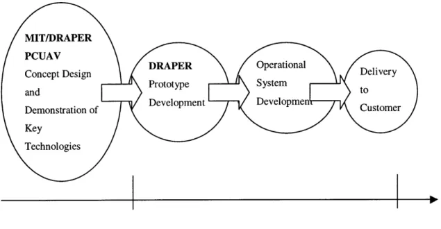
The project would conclude with demonstrations of key technologies that are necessary for development of an operational system. This would validate the unobtainia identified. Lessons learned from the demonstrations should serve to show that the concept is feasible and can proceed to prototype development. Fig 1.1 shows a projected sequence of events that would lead to operational deployment of PCUAV by the end user. MIT/DRAPER PCUAV Concept Design and Demonstration of Key Technologies 2000
Fig 1.1 Evolution of PCUAV
-2004
1.2 Thesis Objectives and Outline
The primary goal of this thesis is to describe the work completed by the first year team and to provide details, rational, and technical highlights of the chosen concept. The description is chronological and addresses the various phases of the first year of effort.
Fig 1.1 shows how the PCUAV concept might evolve into an operational system over the next few years. Under the MIT/DRAPER partnership program, the concept would be designed, developed and key technologies will be demonstrated. After demonstrating the feasibility of essential technologies/approaches at MIT, a prototype would be developed followed by an operational system. The entire development cycle of PCUAV spans five to six years. During this period, several supporting technologies might evolve and these will need to be anticipated and taken into account while developing the concept. In addition, the needs of the end users have to be identified to set the requirements for this system.
Chapter 2 describes the market, customers, and their needs as derived from numerous interviews and literature searches. Customer needs and technical requirements that flow from these needs are prioritized. Chapter 3 describes the various concepts that were explored, the downselected concept, and presents a detailed functional analysis of the chosen system concept. Chapter 4 describes the risks involved in the development of the chosen system concept and the approaches taken to mitigate them. Chapter 5
describes the author's experience as student project manager. Chapter 6 concludes the thesis with project status, recommendations and conclusions.
CHAPTER 2
Needs Assessment and Requirements Analysis
2.1 UAV Market Assessment
Unmanned aerial vehicles (UAVs) have been used as early as WW II. In Southeast Asia UAVs flew missions considered too hazardous for manned aircraft, performing photography, real-time TV relay, electronic intelligence and battle damage assessments. Typically, UAV missions were conducted at a fraction of the cost incurred using manned aircraft and at significantly reduced risk to human operators. The significant impact of UAVs in military operations, however, was not apparent until the Gulf War. The U.S military has identified an urgent need for the integration of UAVs in both strategic and tactical units.
Hunter Navy Pioneer Pointer Outrider Exdrone Predator VSTOL Eagle Eye Dragon Sender Global Hawk D arkstar I I Operational Operational Present 2-5 years DARPA initiatives NRL concepts PCUAV MAVs I Technology 5+ years
Fig 2.1 PCUAV system and other UAV programs
Fig 2.1 shows the timeline for various projected UAV programs. The PCUAV is envisioned as a system that might be operational by about 2004. The market for UAVs is still in its early stages of development and is likely to experience significant growth over
UAVs
the next 10 years. The current worldwide UAV market is about $2 billion a year and is expected to grow at 12% per annum through 2005. This comprises just the military air-vehicle segment, which makes up only 15% of the overall market consisting of UAVs and supporting equipment. The PCUAV system has the potential to capture a significant fraction of the market because of its unique features and capabilities.
2.2 Customers and Application Scenarios
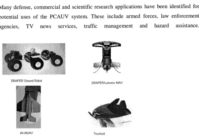
Many defense, commercial and scientific research applications have been identified for potential uses of the PCAUV system. These include armed forces, law enforcement agencies, TV news services, traffic management and hazard assistance.
DRAPER Ground Robot
DRAPER/Lutronix MAV
IAl MUAV Trochoid
Fig 2.2 Potential micro systems as PCUAV child systems
The primary purpose of PCUAV system is to deploy modest capability assets where they are needed at a distance from the user. These assets include mini and micro systems that may be used for sensing, targeting, and communications, and may eventually find application as weapons, as well. Many potential micro systems have been identified. These include ground sensors, miniature robots and micro aerial vehicles with a
maximum dimention of about 6" in any direction. Fig 2.2 shows some of the micro systems, currently under development, that might be used as child systems in PCUAV. They include the CSDL/Lutronix hovering MAV and a few other projects sponsored by DARPA. These projects are expected to mature by the year 2000 or later and hence cannot be effectively integrated into the PCUAV project today. Mini systems are significantly larger and include small aircraft with a span of up to 4 ft.
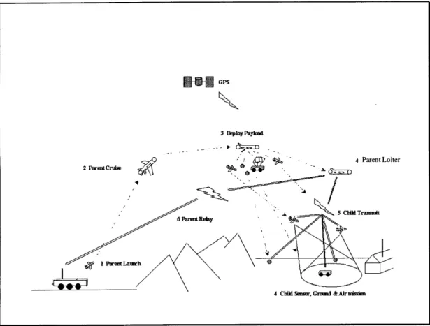
Fig 2.3 PCUAV and a typical mission scenario
Multiple mini/micro systems might be deployed from the same parent as shown in Fig 2.3. Hence, a number of missions might be accomplished with the PCUAV system. A mission can be changed while it is being executed and the most relevant sensors, mini or micro systems can be deployed when necessary. In addition, when a mini/micro system is exhausted, a new one could be deployed from the same parent to maintain sustained presence and continuation of the mission. In addition, a new parent can replace the previous one, thus further extending the mission. Hence, the flexibility that is provided by
the parent child system-of-systems concept might be effectively utilized in many ways not previously available to users.
DARPA has been identified as the primary customer for this project, as the objectives of the project matched closely with their needs. DARPA encourages the design and development of innovative, advanced defense systems utilizing state-of-the-art technologies. One of the goals of this project is to initiate an effort that has high potential to be funded for further development. However, DARPA is not the ultimate customer. The armed forces (i.e., the Air Force, Navy, and Army) use the products developed under DARPA contracts. Hence, the team studied their needs to get a better understanding of real requirements. A few application scenarios have been identified for the PCUAV system. These potential scenarios were used in discussions with the officials at defense organizations to refine the needs and to stimulate new ideas. In addition, a few civilian and scientific research applications were also identified.
While DARPA's needs are motivated primarily by cutting edge technologies, the end user needs are strongly driven by ease of use, compatibility with existing infrastructure and cost. Important end user needs include a high degree of autonomy, portable lightweight hardware, short take off and landing, and compatible fuel.
A number of application scenarios have been identified for military missions. While many existing UAVs meet the requirements of the military services in the near term, a few scenarios have been identified where the parent-child concept can execute novel missions, which can only be executed by the PCUAV system. The following section describes some of the mission requirements.
2.2.1 Nuclear Biological Chemical (NBC) Warfare Agent Detection
Detection of NBC warfare agents requires that sensors be placed within the contaminated region. Some of the challenges include sensor deployment at less than 40 ft. in attitude. Most of the current UAVs fly at much higher altitudes. In addition, they are designed to carry specific payloads that may not include sensors for NBC detection.
Fig 2.4 Ground vehicle and sensor deployment for NBC detection
The PCUAV system can be effective in this scenario. A few commercial off-the-shelf MEMS based biological and chemical sensors are available today. These can be integrated with mini or micro systems. Each of the child UAVs or ground robots can carry different sensors. In an operational scenario, a parent aircraft flies over the region of interest and sends images to a ground station. The user identifies the potentially contaminated areas where sensors need to be deployed. On getting the user command, the parent deploys child systems carrying the most suitable sensors to the designated areas. Fig 2.4 shows the deployment of ground vehicles, carrying NBC sensors, from the parent.
The parent then serves as a communication relay and provides command and control to the ground vehicles.
2.2.2 Mission Operations in Urban Terrain
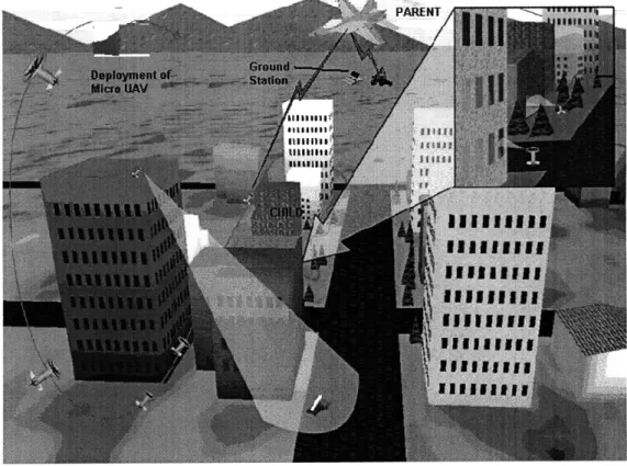
It has been cited that most modem day warfare will take place in cities [9]. In 1993, 18 US soldiers from an elite-fighting unit died on the streets of Mogadishu, Somalia. Russian troops have died on the streets of Grozny, capital of Chechnya. These developments have shown that armies in defensive postures often take shelter in cities and convert the battle into unconventional guerrilla warfare. While the troops of modem armies have been trained to fight in open battlefields, even the most advanced and well-equipped army finds it difficult to operate and win in an urban situation. Difficulties arise due to ruined streets and buildings that limit mobility, large numbers of non-combatants that limit the use of fire support, and tall building structures that affect the ability to communicate.
Fig 2.5 shows the PCUAV system making use of a DRAPER MAV for operations in an urban environment. The PCUAV system would deploy micro UAVs inside such cities and provide information about activities that would otherwise be obscured by buildings and other structures. Before storming the city, the PCUAV system would provide vital information to troops stationed outside the city. Such information is difficult to obtain with the current UAV systems because of their size and maneuverability constraints. When army operations take place in the city, real-time information can help the commanders to make appropriate decisions.
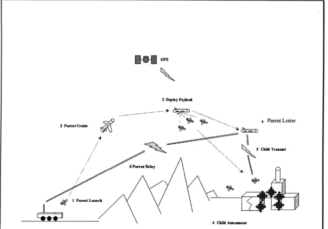
2.2.3 Bomb Damage Assessment
GPS
\z "
3Deply Paylvad ' ... 4 Parent Loiter ~L .5 'MM 'Tia all 2 Parent Cruise .."//~ 4 C Am 4 ChI AeidsrFig 2.6 PCUAV applied for bomb damage assessment .0- 1 ParentLu
Assessment of damage caused by artillery shells or air raids can be achieved by close range reconnaissance. While conventional UAVs are prone to ground fire, the PCUAV system can be effectively employed to get an accurate estimate of the damage by fusing the images from multiple angles to generate 3-D images of the target. With these 3-D images, untargeted/undamaged areas can be accurately geo-located and retargeted. Fig 2.6 shows a typical application scenario with the mini/micro systems sensing images of the targets from various angles to generate 3-D images.
2.2.4 Naval Application
Advantages of having multiple distributed systems include sensing from various locations simultaneously. For example, Fig 2.7 shows a ship launched PCUAV system deploying sonar buoys from a parent in order to locate enemy submarines.
A GP 4 Paeat Lier ~ x*""c~ c~~ZD.g 5 CiHI Tmkm ., 2 Pa.MtCr~be /I m a t _ 6 t iah 3 De by PaybaL e 4.Ckm Sauefk1ue
Fig 2.7 PCUAV locating submarines by triangulation
11
h.
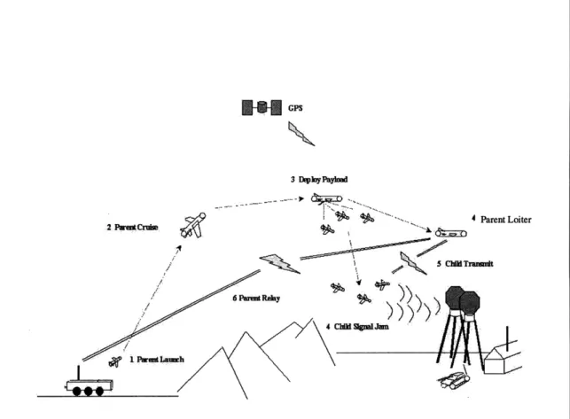
2.2.5 Radar Jamming
Micro and mini aircraft may be useful for jamming radars at close range. The power required to jam a radar is inversely proportional to the square of the distance to the radar. Micros that can closely approach the radar receiver can be very effective in jamming the radar compared to conventional systems, which must operate from longer ranges. Preliminary studies indicate that only 1W of power is required to effectively jam a radar at a range of 2km or less. As shown in Fig 2.8 the micro/mini system can be envisioned to be deployed close to the enemy receiver. Because of their small size, the micro/mini systems can be operational for only a short duration of time before they run out of power. The parent UAV could then replace them by deploying a new set of micro/mini systems.
2.2.6 Scientific Research Applications
Certain scientific applications, such as studies of atmospheric phenomenon like hurricanes and tornadoes, require sampling of data simultaneously from distributed locations. A parent would fly close to regions of interest and deploy sensors or micro UAVs close to such phenomena. Specially designed micro UAVs might fly further into locations where data needs to be sampled while the parent stays at a safer distance. The micros would transmit their locations and sensor data to the parent. The parent would collect such information from micro systems and transmit it to the ground station for further analysis. Such atmospheric phenomena are not predictable. A PCUAV could fly to a location where they are detected or chase a moving tornado. Hence, PCUAV may enable research that is difficult or impossible with existing systems. Relatively low flight velocities of parent and children may limit this application.
2.2.7 Other Applications
The PCUAV system might also be used for drug interdiction, wildlife and forest inspection, border patrol and other non-military needs. These applications require searching over large regions to detect events of interest. Most of the events of interest are transient in nature and hence require the sensors to be placed at the right location and at the right time.
PCUAV can perform a collaborative search. The parent and child systems could simultaneously search different parts of a region of interest. The parent would collect images from child UAVs and transmit them to the ground station. The search pattern can be repeated to detect changes over time. Fig 2.9 shows typical collaborative search patterns by parent and child UAVs over a region of interest.
-hild I Search -,Parent Search Pattern -Search Area Child 2 Search Pattern
Fig 2.9 Collaborative search by PCUAV
In the near future, some space-based applications like interferometry using distributed satellites, can use PCUAV system-of-systems concepts. An experiment on similar lines is being conducted at Stanford University. The project, called OPAL, consists of a parent satellite that would deploy smaller nanosatellites.
2.3 Requirements Analysis
A number of potential PCUAV missions were identified in the previous section. All of these missions can be executed by the PCUAV concept due to the flexibility offered by its system-of-systems nature. In order to define the PCUAV system in more detail, it is necessary to identify the system requirements that would satisfy most of the customer needs.
2.3.1 Customer Requirements
Table 2.1 was developed to prioritize the original customer requirements. These requirements and their priority ranking were generated by the team upon discussions with members of the operational community. A high score of nine was assigned when the requirement was strongly desired by the customer. A low score of three was assigned when the requirement was not very important to the customer.
Customers were prioritized based on their assumed relative importance to this project. This is shown by the numbers in the second column. A higher score was assigned to the more important customer, 100 being the highest possible score. These numbers were obtained from the market survey, interviews with potential end-uses and objectives of the project. DARPA was assigned the highest score of 100 as it was felt that the objectives of the project, described in Chapter 1, matched closely with their needs.
The priority ranking of each customer need (score 9-5-3) was weighted by the relative importance of the customer to the project (column 2), the results were tallied, and a total score for the customer requirement was generated. The total scores of all customer requirements were compared and ranked (last row of Table 2.1).
The most important customer need turned out to be ease of use of the system. This meant that relatively inexperienced users should be capable of operating the system with very little training. In addition, the system should have some degree of autonomy. The other highest scoring customer requirement was compatibility of fuel and communications systems for efficient integration with existing facilities. Heavy fuel is used by the Army and Navy. Use of any other fuel by the PCUAV would require additional support equipment and would increase logistical complexity. One of the main reasons for the failure of the Outrider program has been cited to be its inability to operate
Si ili ,
SCustomerslMarket Segment i,, -11 I i -01; l m -n -n = ( z > o1~21~ 0 "0 " 0 W M > aCD ON c -n-o 0 I -, Q Easy to Use -L ID Cs= .3 =©mmc == > (1 m= =c All weather Operations
10 (00
.= * .5., t o
-: mm© W' 1o s. ,~s €a a' 'io (0 Lo Obpct ive Lf ocation Error iie ::
0: 0 0 L-owtbl Miso yceTm
10 c Cs .C 0CC"C RieI lative Im porta n o Custom
-J
Cs 10 LoEasy to Use
C 1 0 ww to to co to W co cc c 1 w ,Compatible fuel saCe hanling)
10
S c Shory/ght CapabilityT/O
-1 .- - .c t Long Rangecost ofOwnershi
co 0 C t 0 c W t C S C CA Cd W W I eateb Lcation 10 c 0 -Lw MissionCCclesTime 100 S10 10 a M to W C" 0 cr at.cs C co C"0to c Cs 0 (CD C ) opg edrantebll t -I 01 C. 0 .) I C s I . ( ) ID I 1
CID -L 4-1 coco 0 (1 (0 Cal o 0 A J W CA C Cn W al WI I W c S hort T/t
C5. i N rN Cas a W 5 Cs 0 Long__Life o __ __System -b M ~"I I I I a I 01 car I 01M M 1- aW WC . a
Custos , Needs
In InM 3 0 I
:: :: .- .: :: --- ---- -...
enc
.01 meo o a o ame
a hugrated: vekhdeat M Z 2: x 0 0. : i
aox '0l eodtaa
3 to
SI I f I I I I 11 a
mMlil esrd ihon
.omo. . Aum~ft~tonmu Guianetogamn and Cntol
10 in OIo al. O Sth ltfmb
. te .. . i Robust
--- c o m e w o Low specific lualconsumptica a e a .. . . 1. 1. a Liht Weight Stmcture
re .1,1 .o . . .ChidVehicleMaag entand Control
. Wco o . . . . . Versaft.e Senasr
0 .1 I~j~cccur~le..orm jlortm
a o C O o coa o o o n
-I aa an 0m c -1 o a ,a o1 .Weatherresihtanthardafeprotecthn(rain.at
-100
0 0 w w . IihRliblt
or 0 CIO w a a a w I Uar ritainabl ellet~I(~l Co~clo no Rc~rn cooo o o maceas
a m o omlo a m .o, Adaptable 10 multipl mi-ins
0 0 0 . 0 to Modular Design ~ 7-F 7F - -- 0 .a , .0
Sa oEasy l. 0o. 01o010.o Setup is .C ..w . CO Coisin Avoidance
om o o o l o o I- m Mu0 communication Capaby
0 10 0 0 - 0 - - om Hah te data inks
CO 01 in o m 1o IHgh System Redundancy
co
.oc in
o aooo 1og we of critilhmp
. .o.o no .. . . cmpoent
amoo 0 0 Useouppomb of COTSm Sofw
aco a a a oo o e bnshFlMnlah nhb
0C O a o lo a .11.. ec n IO c F m elta e Prpulson Systemse
anOooon 0 .1 0101
cooiponsooDM
1 . . . .Grund e onPreciesonedingin 10 o 0 0 a e c- u n rgeonbano d aintanms c Seo a m
S0 0 0 a Opn ysemArhiecur 0 0 0. 0 CIOtoHig nweabld . 0 .11010 0 a a a DFMA o a a.cr.0 utoittvec000lepos a 9,9 anb,,d ata torae caacit ai IclMaa a L l
2.3.2 Technical Requirements
Having ranked the customer requirements, several technical approaches/ requirements for each customer requirement were derived. In addition, a preliminary functional flow analysis was performed to identify the basic functional requirements of the PCUAV system (e.g., communication between multiple systems). Technical requirements/approaches to perform these functions were also obtained. As each technical requirement was developed, its influence on each of the customer requirements was noted in the QFD matrix as shown in Table 4.2. A high score of nine was given when the technical requirement strongly influenced the customer need; five for moderate influence; three for mild influence and zero for no influence.
The relative importance of each customer requirement, derived from the previous QFD matrix, is shown in column 2. The score for each technical requirement was tallied and a total score was generated. The total scores of all technical requirements were compared and ranked. Integrated parent-child vehicle design turned out to be the most important technical approach. This is a novel approach conceived by the author. In this approach, the parent is integrated with a relatively large child system (mini UAV). Some of the subsystems of the mini aircraft are used to augment the parent's capabilities while the mini is integrated with the parent. Thus, the mini aircraft would contribute to the performance of the parent. The next chapter discusses this approach in detail. Because of its relatively large size, the mini aircraft, as compared to the micros, can carry more capable payload sensors enabling a spectrum of sensor data collection capabilities. Because this approach is new and different, it is a kind of unobtainium and satisfies one of the primary objectives of the project.
2.4 Competition
The concept of a parent system assisting a child system has been witnessed both in terms of aircraft launching other aircraft and on Apollo missions. Solicitations requesting proposals for a parent-child UAV system have been put forth by government agencies. These developments and the following show that potential competition exists for the PCUAV system.
2.4.1 CAMMS
The Northrop Grumman Corporation has successfully demonstrated the autonomous control of four unmanned aerial vehicles by a single operator using the Cooperative Aggregate Mission Management System (CAMMS)[10]. The flight demonstration was conducted on July 25, 1998 at the Naval Weapons Test Center, China Lake, Calif. CAMMS software performed detailed mission planning and assigned each vehicle specific flight profiles to cooperatively execute tasks. Potential applications of CAMMS include unmanned combat air vehicle concepts (UCAV). All the aircraft involved in this test were large UAVs which took-off separately and landed separately. Although the other details of the flight test were not available, it is presumed that this project has the potential to compete with the PCUAV system.
2.4.2 Sender
Sender is a lightweight, low-cost, small UAV developed by the Naval Research Laboratory (NRL). This portable system with four foot wingspan has a one way range of 100 miles. These features make it very attractive for low cost missions. The Sender, however, has some limitations. It has a very high wing loading requiring a sophisticated launch mechanism. It also has limited loiter capability and small payload capacity and its communication system cannot transmit high bandwidth data. However, miniaturization of electronic systems can significantly enhance the capabilities of this system. Fig 2.10 shows a Sender UAV and some of its features.
Fig 2.10 Sender UAV
Electric Drone
Portable-Packed in suitcase
Speed: 50 - 90 kts One Way Range: 100 m iles
Payload: 2.5 Ib
Wingspan: 4 ft
CHAPTER 3
Concept and Architecture Development
Three different PCUAV concepts and their operational system architectures were considered and compared against each other, in terms of performance and functional capabilities, for a given common mission. Because of the diverse nature of the concepts, the mission was not specified in detail but was broadly defined as follows:
1. The system should execute a mission at a distance of 100 km from the point of launch. 2. The mission duration at the point of interest should be 20 minutes.
3. The system (or the most valuable parts of it) should return to the point of launch Fig 3.1 shows a typical mission profile of a PCUAV concept.
The team formed three groups to investigate the three system concepts listed below
1. Multiple Independent Aircraft 2. Integrated Parent Child Concept 3. Micro Systems Cargo Transport
Each of the concepts had its own advantages and disadvantages. To gain better insight, the concepts were further developed to meet the objectives of the mission and the customer needs identified in the previous chapter.
3.1 Concept I: Multiple Independent Aircraft
This concept consists of multiple independent aircraft that would take-off and land separately. These are relatively small vehicles of about 5.5kg take-off weight with a payload capacity of about 400g.
This concept does not involve challenges in terms of vehicle design as aircraft of this size are in the current inventory. However, many system challenges need to be addressed. Each of the aircraft must be capable of operating independently. While executing a mission one of the aircraft can assume the role of a parent. This concept was investigated to get a better understanding of existing systems that can be used as PCUAV without the deployment and retrieval features.
3.1.1 Advantages of Multiple Independent Aircraft
System Redundancy: Unlike the other Parent-Child concepts, this concept does not have
a single point failure. In the case of loss of one aircraft, another aircraft can replace it and the mission could continue uninterrupted. Hence, the probability of mission success is higher for this concept.
Indefinite Time over Target Area: The vehicles at the target can be continuously
replaced with new aircraft and the mission could be sustained over an indefinite period.
Formation Flight to Destination: The aircraft can fly in a V- formation (like a flock of
migratory birds) and hence reduce the induced drag on some of them, thus increasing range and endurance.
3.1.2 Disadvantages of Multiple Independent Aircraft
Many separate vehicles must be supported. All the aircraft must take-off and land independently. Use of a large number of independent vehicles increases the complexity in the logistics of operations and handling. Because the aircraft are relative large compared to micro systems, they are less maneuverable and can be more easily detected and targeted. Hence, the system is not capable of executing all of the missions identified in the previous chapter, such as operations in an urban environment.
3.2 Concept II: Integrated Parent-Child
UAV being deployed
Fig 3.3 Integrated parent-child concept
The integrated parent-child concept, shown in Fig 3.3, explores the possibility that the parent might be integrated with the children to obtain simplicity and cost reduction for the total system. The children are relatively large compared to micro systems. Their sensing and communication capabilities are comparable to the parent UAV. However, they are smaller and have much less range and endurance. Also, the children are integrated with the parent in a manner so that they can contribute to the parent's performance rather than simply act as payload during cruise and/or loiter.
3.2.1 Advantages of Integrated Parent-Child
The child UAV's engines produce thrust during take-off and cruise. The additional thrust significantly reduces the take-off distance required by the parent. Since the engines are started at take-off, problems related to remote-start of piston engines are avoided. In addition, the response time of the system is reduced because the parent can travel faster to the mission site. The parent-child configuration can be optimized to provide a net aerodynamic advantage to the integrated system and hence increase range and/or endurance. While the child UAV is integrated with the parent, its sensors might be utilized. Thus, for example, a child UAV's camera can be used by the parent.
3.2.2 Disadvantages of Integrated Parent-Child
Because of the novelty of this concept most of the systems involved in the integration need to be developed. Instabilities may occur during deployment and/or recovery. Since the child UAVs are relatively large in size, the parent can carry only a few of them. Also, many of the missions mentioned in the previous section cannot be accomplished because of the large size of the child UAVs. Aerodynamic properties of the parent are altered after deployment. So, the parent needs to be designed for stable operations with two or more different aerodynamic configurations. Separation and deployment mechanisms will increase complexity.
3.3 Concept III: Micro System Cargo Transport
COTS MAVs
Extended Range
Tank
Fig 3.4 Micro system cargo transport
Concept III is envisioned as a bus for micro UAVs. A number of micro systems have been identified as potential child systems. Some of them are shown in Fig 2.2. Concept III enhances the performance and capabilities of these systems by carrying them to the destination, deploying them, and coordinating their activities. Since a wide range of micro systems are likely to be available in the future, it is proposed that they be packaged into a standard PCUAV pallet that can be dispensed by the parent. Standard PCUAV pallets have an internal dimension of 6" so that they can carry most of the proposed micro UAVs. Fig 3.4 shows a parent aircraft carrying four pallets; the first contains a Draper/Lutronix hovering MAV; the second contains a stack of fixed wing MAVs; the third contains a ground robot; and the fourth contains fuel for extended range.
3.3.1 Advantages of Micro System Cargo Transport
A wide range of systems can be delivered to the destination. Most of the missions mentioned in the previous chapter can be executed by this concept. One or more of the cargo pallets can be replaced with a fuel pallet to increase the range or endurance.
3.3.2 Disadvantages of Micro System Cargo Transport
Because of the small range of communications of the micro systems (about 600m - 1000m) the parent has to fly close to them and hence is vulnerable in hazardous
situations.
3.4 Downselection of Preferred Concept
Characteristic Weighting Arch I Arch II Arch III Arch I' Arch II' Arch III'
Multimission 10 3 4 5 30, 40 50
Unobtainium 10 3 4 5 30' 40 50
Reusability 8 5 3 4 40 24 32
Gather Info/Payload Cap 8: 3 4 5 24' 32 40
Reliability (M ission Execution) 8 5 3 2 40 24 16
Short T/O and Landing 8 3 4 3 24' 32 24
Portability 7 2 4 4 14 28 28 Feasib ility 5 5 4 3 25 20 15 Covert/Stealth 5 2 3 5 10 15 25 A 11Weather 4 5 4 3 20 16 12 Cost 4, 1 2 3 4 8 12 Maintenance (Refuel-charge) 3 4 4 4 12 12 12 273 291 316 MAX 400
Table 3.1 Comparison of concepts and downselection
The three concepts that were explored had many advantages as well as disadvantages. A common set of characteristics, shown in the first column of Table 3.1, was identified. These characteristics include the ability to execute a wide range of missions (multimission), challenges involved in developing the concept (unobtania) and other features that would satisfy customers needs (Short T/O and Landing, Portability etc.). The characteristics were ranked according to their relative importance to the
project (column 2). The concepts were given a priority ranking on a scale of 1-5 depending on how well they demonstrated these characteristics. The ranking figures were supported by results from preliminary design calculations of the three concepts for the mission identified in Fig 3.1. The score for each concept was tallied and a total score was generated. These scores were compared and it was found that there was no clear winner because the concepts fared very well relative to each other. Instead of choosing the best concept, the team decided to incorporate the most interesting features of all the concepts and generate a new concept that would be explored further. This resulted in a concept consisting of a fleet of vehicles of the type shown in Fig 3.5.
3.5 Concept IV : Integrated Parent/Mini/Micro System
Fig 3.5 Selected vehicle concept
Concept IV incorporates the various features of the previous three concepts while attempting to overcome their disadvantages. The parent carries two sets of child systems
- mini UAVs on the wing and micro systems in the fuselage. Mini UAVs are small
PARENT VEHICLE
aircraft Micro
UAVs
aircraft as in Concept I. Micro systems are packaged in pallets as in Concept III. The system would take-off on a rail and/or with rocket assist to give it a short take-off capability. Parachute landing is proposed for retrieving the parent and the mini.
Fig 3.6 shows the concept operation in a three layered architecture. The least valuable of the assets is closest to the ground, while the more valuable ones are at higher altitudes. While mini UAVs fly at about 1 km from the surface, the parent flies at about 2-3 km above the ground. Micro systems are either on the ground or fly very close to it. Since the micro systems are limited in their range of communications, the mini UAVs act as relays between the micro systems and the parent. However the parent has a stronger transmitter and can transmit commands directly to the micro systems, and also provides communication with the ground station.
Though the architecture is complex, the flexibility provided by the availability of a fleet of systems, in layers, with various capabilities, makes this concept applicable to all the missions discussed in the previous chapter.
3.5.1 Roles of the Vehicles
The following are the roles of the different vehicles involved in Concept IV.
Parent UAV
1. Carries and deploys the mini and the micro systems at the mission site. 2. Coordinates the mission by sending commands to the deployed systems
3. Communicates with the ground station ( either directly or through another UAV like Predator)
4. Carries a sensor suite of its own (e.g., camera, radar, IR) and gathers information on its own.
5. Other functions envisioned for the parent include refueling and retrieving the mini UAVs.
Mini UAVs
1. Carry their own mission payloads
2. Act as a communication relays between the micros and the parent 3. Deploy miniature ground sensors with precision
4. Collect data from miniature ground sensors 5. Help the parent in multisensor surveillance
6. While integrated to the parent at take-off and cruise: a) Provide additional thrust to the parent
b) Provide aerodynamic advantage to the parent c) Provide an array of sensor capabilities to the parent
Micro UAVs, Sensors, Robots, Ground Sensors
1. Carry various sensor packages for executing a wide range of missions 2. Transmit the sensor information to the mini UAVs
Fig 3.7 shows the PCUAV in both its strategic and tactical roles. The system is being designed for two-man-portable tactical Forward Line of Troops (FLOT) applications. It can also be modified to be carried under the wing of a Global Hawk class UAV and dropped at destinations much further away from the point of launch. In its strategic role, a PCUAV can communicate with a larger UAV or a satellite to transmit information to the ground station.
Fig 3.7 PCUAV operations -tactical and strategic roles 3.6 Functional Flow Analysis
The team created an initial version of the functional flow diagram for the PCUAV system. This was modified for each of the three concepts discussed above. After downselecting the forth concept, the different system elements in the architecture and their individual roles were identified. To ensure that some vital functions were not ignored, a detailed functional analysis was performed. A top-level functional flow
diagram is shown in Fig 3.8. The details are included in Appendix A. Some elements of the functional flow diagram are briefly described below.
Functional Flow Diagram
System Launch -> Cruise Preparations to mission are
arent fles back
on vehicle follows n ies back
Planning waypoints
mini expended
L Deploy ~r. ansmit/Relay visual data to ground station
I f M Retrieve mini.,.
Deployment Drop Mcro se...nsor... > vehicles ofMicro Relay sensr output to Refuel lmini
parent vehicles
Fig 3.8 Functional flow diagram of the PCUAV system
System Preparation: Parent, mini and the micro systems are assembled together, fueled
and their batteries charged. A mission plan for the parent is generated and the waypoints are loaded. Parent is set on the take-off mechanism (e.g., rocket/rail launch) and readied for launch. All sub-system checks are performed.
Launch - Cruise to mission area: The parent, with its mini and micro systems, is
launched using a short take-off mechanism and cruises to the mission area by following the designated waypoints. On reaching the mission area, the parent transmits a visual image of the target location to the ground station. The user would then confirm/locate the target.
Mission Planning for the child systems: On confirming the location of the target,
mission plans would be generated for each of the child systems. Mission plans consist of a list of waypoints that are time stamped. Activities of various systems involved can be synchronized with the aid of these plans. In the current version it is envisioned that any updates to the child system's mission plan will be transmitted to the parent which would
download them to the children. All the mission plans are generated on the ground station with human input.
Deployment of the mini and the micro system: Mini/micro system's electronics are
activated and all sub-system checks performed. Wireless communication links between the parent and the children are established. Flight conditions for deployment are verified. The deployment mechanism is activated and one or more children are released.
Receive Visual/Sensor Data from the child systems: While following their flight paths,
the child systems gather sensor data and transmit it to the parent (directly in the case of a mini and through the mini in the case of micro systems). Sensor data is envisioned to be mostly video information, which needs a large bandwidth for transmission to the ground station. Hence these images are fused and compressed onboard the parent before transmission to the ground station.
Refueling/ Retrieving: In one of the scenarios envisioned, the mini UAVs are refueled by
the parent to sustain the mission. At the end of the mission, the mini UAVs could also be retrieved by the parent and returned to base, or possibly be refueled by the parent and fly back independently.
Fly back/Expended: In the case where the mini UAVs are not recovered, they follow the
CHAPTER 4
Technology Exploration and Risk Mitigation
Concept IV, described in the previous chapter, was presented at a Concept Design Review (CDR) held at Draper Laboratory to obtain opinions and feedback on the choices made during the trade study and downselection process. Details were reviewed during the CDR and it received a positive response along with some statements of concern. Innovative thought was cited as significant and system complexity was voiced as a concern. In order to assess the degree of complexity involved in the system concept, the team decided to work on identifying the key technologies that must be developed. From the functional flow analysis, technologies required for each of the sub-systems were identified. While an attempt was made to incorporate many clever, creative and unconventional approaches into the design and development of each of the subsystems and their interfaces, existing approaches proved to be more effective in many instances. For example, the team felt that a conventional rocket/rail launch system for take-off and parachute landing system were effective approaches for the launch and recovery of the parent.
The overall aim of the project has been to develop a unique technology or approach. This would require supporting technologies and approaches involving clever, creative and unconventional approaches that have been defined as unobtainia. Because of their nature, unobtainia involve high-risk elements that can jeopardize the project objectives if they are not addressed early into the project. For example, they might require time and effort beyond the resources available to the student team and the project deadlines. They might even be unfeasible with available technologies. These unobtainia were identified and the technologies associated with them explored. Attempts were also made to maximize the use of available components in the sub-system designs.
Novel-Subsystem
Technologies/
0proaches
E d o E E :E Z 0 E >Technical
0 a
o ,Requirements
Multiple sensor data fusion 9 0 Stable Platform 7 5 0 0 0 0 1 0 0 03
Expert Mission Planning 7 0 1 E 0 1 C r5 0
1 4 5 3 2 6
Integrated vehicle design 10 5 5 0 0 0 0
Efficient Aerodynamic/Control Design 9 5 0 0 0 0 0
Multiple sensor data fusion 9 0 0 0 1 0 3
Autonomous Guidance, Navigation and Control 8P 3 0 0 3 5 0
Stable Platfbiliorm 7 5 0 0 0 0 0
Expert Mission Planning 7 0 1 0 1 5 0
Rugged /Robust 7 5 3 0 0 0 0
Night Sensor Technology 71 0 0 1 0 0 0
Efficient Data Collection and Processing 6 0 0 0 5 1 3
High Lift Capability 7 5 0 0 0 0 0
Low specific fuel consumption 6 1 0 0 0 0 0
Light Weight Structure 6 5 0 1 0 0 0
Child Vehicle Management and Control 6 0 1 0 5 5 0
Adaptable to multiple missions 5 0 1 5 1 5 1
Modular Design 5 5 3 5 0 0 0
Ground Sensor Precision Landing 4 0 0 5 0 0 3
Open System Architecture 3 1 0 5 1 0 1
Compact Design ( to fit in suitcase) 4 1 1 3 0 0 0
292 108 110 108 136 65
Table 4.1: Unobtainia identification and relative importance
The three-layered architecture of Concept IV involves micro-systems in the lowest layer. Technologies involved with these systems are being developed by CSDL, Lincoln Laboratory and by many DARPA sponsored projects. From discussions with experts working on these projects, it was concluded that an operational MUAV might be available in about 2-3 years. It was decided that the development of MUAVs or technologies associated with them was not a significant aspect of this project, however interfaces to the micro-systems will be developed to make use of them when they will be available. The unobtainia associated with the parent and the mini UAVs have been classified into two categories - vehicle unobtainia and systems unobtainia. Table 4.1
shows some of these and their relative importance to the technical requirements derived from customers needs.
4.1 Vehicle Unobtainia
The chosen integrated concept has many unique features. Mini aircraft are attached to the parent's wing to provide aerodynamic advantage and added propulsive power. As identified in the functional flow analysis (Fig 3.8), the PCUAV can demonstrate many novel functionalities. These include deployment, mid-air refueling and potential retrieval of mini UAVs by the parent. The unobtainia and risks involved in achieving these features and designs are described below.
4.1.1 Vehicle Configuration and Deployment of Mini UAVs
A number of challenges are involved in the design of parent and mini vehicle configurations and their integration. Various configurations were explored by placing the mini at different locations of the parent. Two planforms - conventional and delta - were used for the parent and the mini. The goal was to find an optimum configuration that would achieve the following objectives.
a) Efficient Vehicle Aerodynamics: Presence of a mini aircraft close to the parent significantly affects the aerodynamics of parent-mini combination. A configuration that offers maximum lift-to-drag ratio is desired. This would tend to give the parent-mini combination increased range and endurance.
b) Stability and Control: Parent-mini configuration should provide a clean and stable separation during the deployment phase. Clean separation would require that the parent design provide enough clearance so that the mini does not hit any of its surfaces during deployment. Stable separation requires parent and mini to remain stable during and immediately after deployment. These considerations hold for refueling and recovery as well.
5
7c
I
Fig 4.1 Parent - mini integrated-configurations
lb
=KIII
4b7b
7 . ... qp:cJ
I;L~iirsk=~=4:
~;~4p~4
~-~r=S J-;~ ~i I ~T~4~T=TT~
CL-=IL~c) Structural Loads: The mini aircraft should be attached to the parent at locations such that minimal additional strengthening of the parent structure would be required.
Twelve candidate parent-mini configurations and integration layouts, as shown in Fig 4.1, were generated. Analytical aerodynamic performance analysis of some of these integrated parent-mini configurations was performed [7].
Integration-concept 1, ib, 2 and 3:
In these concepts, mini aircraft are mounted on pylons of the parent. The mini aircraft are located away from the centerline of the parent. Hence they need to be deployed simultaneously. This is necessary so that the parent does not encounter unsymmetrical forces. This requires that the parent should have large control surfaces and results in inefficient operations. The mini aircraft are deployed behind the parent. Soon after deployment, mini aircraft might invert and lose control in the vortices generated in the downwash of the parent. Mini aircraft need to be provided with enough control power to overcome this problem.
Integration-concept 4, 4b, 5 and 6:
To overcome the problems of deploying the mini aircraft in the vortices behind the parent, these concepts were explored. Mini aircraft are positioned above the parent so that they get maximum clearance during separation. After deployment they fly forward. These concepts are expected to have a stable separation, since the vortices behind the mini are less disturbing to the parent than the reverse concepts. Also since the mini aircraft are located along the line of symmetry of the parent, they can be deployed one at a time.
Integration-concept 7, 7b and 7c:
Mini aircraft are placed at wing tips to provide aerodynamic advantage. Effective span of the parent-mini combination is increased by this configuration. However the mini is now in the strong wing-tip vortex .
Integration-concept 8:
Mini wing structure acts as a strut. This can reduce the structural weight of the parent, however this configuration has less aerodynamic advantage than the other concepts.
4.1.2 Integrated Fuel, Data, Power and Mechanical Interface
Integration of the parent and mini is required so that some of the parent's resources, such as fuel and electric power, can be used by the mini and some of the payload capabilities of the mini can be used by the parent. Exchange of these resources, as well as digital information, in-flight can be accomplished by an interface[8]. Features needed for such an interface are detailed below.
a) Preliminary studies show that for a two-hour mission, a mini aircraft would require 3.2 kg of batteries if it were propelled by a 0.5 horsepower electric motor. For the same mission and power setting, it would require about 180g of fuel if it were propelled by a combustion engine. Hence, it was decided that a combustion engine rather than batteries should power a mini. Unreliability associated with remote starting of combustion engines significantly risks the execution of a mission. Hence it is envisioned that engines of the mini be kept running from the start of the mission. Since the fuel tanks of mini aircraft are significantly smaller than for the parent, a fuel transfer interface between the parent and mini was envisioned. In addition, while a mission is being executed, the mini aircraft could be refueled by the parent through the same interface.
b) Power interface: The mini aircraft have limited weight carrying capacity. Hence, the size of their batteries is restricted. This would require the parent to recharge the mini aircraft's batteries during cruise. This requires an interface between the parent and the child through which power could be transmitted.